[5] Abraham WT, Foreman B, Fishel R, Hass G, and Moe B, Fluid accumulation ... [6] Hans Pasterkamp, Steve S. Kraman, and George R. Wodicka. Respiratory.
Towards a Method for Early Detection of Congestive Heart Failure with an Electrocardiogram and Acoustic Transducers Alexander Kaiser, Carissa Pocock, Pratibha Sharma, Nickolas Browdues, Kimberly Newman, Senior Member, IEEE and Frank Barnes, Fellow, IEEE University of Colorado Boulder Boulder, USA Abstract—In an effort to improve the reliability of the
detection of congestive heart failure, a method utilizing phase shifts of cardiac and thoracic acoustics coupled with ECG signals is described. The system consists of bipolar ECG electrodes placed on the pectoral muscles and acoustic transducers that monitor four locations across the chest and back. The method is tested on six healthy individuals; there are five males and one female. Amplitude of the acoustic and electric signals vary significantly so spectral analysis is utilized for classification. Frequency analysis of the data shows expected values for healthy individuals. For this initial set of data, cardiac acoustic responses are below 400 Hz. It is expected in patients with congestive heart failure to have frequency responses far beyond 400 Hz. This is due to a “crackle” sound that is produced in the lungs as a result of pleural effusion. It is also anticipated to see significant differences in phase shifts among healthy individuals versus individuals with congestive heart failure. Keywords— congestive heart failure, ECG, stethoscope, wearable monitoring system.
I.
INTRODUCTION
In 2005, the mortality rate in the United States due to coronary heart disease alone was 445,687 [1]. Congestive heart failure is a chronic condition that may develop rapidly so a method that can be used in the home to detect the onset of symptoms could be very beneficial. Congestive Heart failure may affect one side of the heart but mainly affects both sides. There are two main forms of congestive heart failure, systolic heart failure and diastolic heart failure. Systolic heart failure is a result of the heart being unable to effectively pump blood out of the heart. In diastolic heart failure, the heart should be relaxing and filling with blood but instead there is an increase in left ventricular filling pressure. When the heart experiences systolic or diastolic heart failure fluid may build up in regions of the body. The fluid buildup can lead to lung congestion, up to pleural effusion, leading to fatigue, shortness of breath, and weakness in the lower extremities, however the presence of these symptoms or lack thereof does not contribute greatly to the diagnosis due to the broadly categorized nature of these symptoms [2]. Congestive heart failure is most commonly diagnosed with knowledge of medical history, physical examinations, and specific lab test.
Detection of congestive heart failure in the early stages is hard to achieve. In the home monitoring area, the current guideline is to measure weight which increases and can be treated within a window of three to five days before an emergent situation occurs [3]. Recently, studies in patients with implanted devices have shown improved resolution by monitoring intrathoracic impedance which is elevated roughly eleven days before an emergent event occurs [4][5]. However, this approach is limited to individuals with implanted devices. An alternative approach using a wearable system is proposed here to measure impedance changes in the lungs due to increased fluid retention. A combination of an ECG and stethoscope could be used to detect the electrical and acoustic shifts that occur as the heart generates signals and the person inhales and exhales . Since water has a much larger impedance value than air, the reflection of sound can be detected using this approach. Progress towards creation of an instrument to capture this information is provided as a proof of concept for a new way to perform early detection of lung fluid volume. II.
METHODS
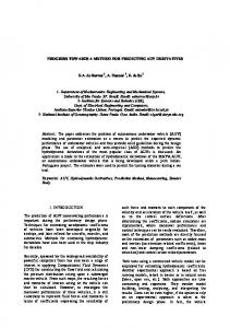
Six healthy individuals between the ages of 19 and 23, five male, one female, participated in this study. The data from one male is void due to technical issues. The equipment used consisted of silver/silver chloride electrodes and two acoustic transducer with included software manufactured by ThinkLabs. Two measurements are taken with the stethoscopes that are classified as cardiac and acoustic. The cardiac signals are recorded by taking three signals from three positions in sequence with ECG data while the stethoscope is in bell mode. The stethoscope placements are used to cover the signals from the front and back of the chest as well as the lower part of the lung to capture both the signals from the heart as well as the lungs. Each trial consisted of 25 sec intervals, where the subject is asked to breathe at a steady pace, one cycle per 8 seconds. The locations on the chest for placement of the ECG leads and stethoscopes are shown in figure 1.
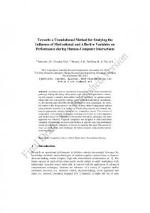
breathing patterns among subjects. However, when examining characteristics of the thoracic accoustic responses, certain generalizations can be made, this in ncludes general normalized amplitude exhibited a sine wave, wh here frequency is depended on the rate of breathing. The frequency analysis of the thoracic acoustics also returns very similar data among subjects. The ECG data varies greatly in magnittude so this information is not used for analysis. However, the ECG device performs analysis on the different intervals of the cardiac cycle. The data is seen in Figure 2 and is used to filter out irrelevant data. If the ECG detects abnormal cardiaac outputs, the data collect for that particular trial would bee discarded and the data collection would be performed again n for that trial.
Figure 1: Overview of stethoscope placemen nt locations The first stethoscope is place ventrally on the left pectoral region overlapping the second rib which is shhown as position A. Calibration is performed to avoid clipping while maintaining a high signal to noise ratio. Addjustments to the level of the output are performed by monitorinng the signals on the Audacity logging software provided w with the digital stethoscopes. The filter setting should also bbe enabled on the stethoscope for both sets of readings. Oncce the system is calibrated for position A, two stethoscopes arre used to take a reading from the front and back of the cheest. The second stethoscope is placed dorsally on the lower rregion of the left trapezius muscle, on the edge of the scapula w which is shown as position C. Readings are then taken on the right side of the chest in the same anteroposterior and dorsoveentral positions as the first recording which is shown as positioons B and D. A third recording is taken at position C and E oon the inner edge of rib 9 and 10. This position is selected to ccapture the lower portion of the lung. The next sequence of data collection capturres the acoustics and the stethoscope is placed in the diaphragm mode. As in the cardiac data collection, an acoustic filter is applied and the amplitude is calibrated for an ideal signal to noise ratio that avoids clipping. For the thoracic acoustic signnal capture, four measurements are made per individual. Theese reading are taken in positions A to C, A to D, B to D, and B to C so that signals can be captured across chest as well aas from front to back. All collected data is converted intoo the frequency ms and analysis domain, with numerical Fourier transform performed on the acquired data. III. CURRENT RESULTS The obtained results varied greatly in amplitude both mpensate for this acoustically and electrically. In order to com variation, the results are normalized for eeach individual’s extracted data. Once the data is normalized, comparisons among acoustic frequency responses are conducted. The results of all the individuals’ cardiac acooustic frequency analysis are below 400 Hz. With respect to the thoracic acoustic response, there is significant varriability between subjects. This is due to the uncontrollable naature of different
Figure 2: Average intervals of o cardiac output among individua als The results of the experiment retu urned the anticipated data where all subjects’ cardiac acoustic responses are below 400 Hz. In figure 3 and 4 subject C’s cardiac acoustic frequency and time graph is displayed. The cardiac acoustic frequency response below 400 Hz is ideal because congestive heart failure is anticipated to have cardiaac acoustics that encompass a much higher frequency range, ab bove 1k Hz as a maximum [6]. When compared to the maximum of 400 Hz from the data y individuals’ observations collected, it is likely that in healthy of a significant difference among frequency analysis can be seen versus individuals with congesstive heart failure. It is also anticipated that the severity of cong gestive heart failure may be distinguished based on the magnitu ude and specific frequency of the “crackle” sound. This is because crackles are produced by sudden openings in closed airwaays within the deflated lung region. The opening will depend d upon the progression of tension within the tissue of the lun ngs [7]. Thus depending on the degree of congestive heart failure f different frequency responses is expected.
other issue that needs to be Absorption of the signal is ano resolved. There are two sources th hat would trap the acoustic signal: reflections due to impedan nce mismatching, and total internal reflection. Total internal reflection r occurs when the propagating wave crosses the barrrier at a large , and has a slower velocity in the medium than n the velocity outside of the medium. Total internal reflection follows (1), however, the e (2) occurs. maximum angle , is defined when equation (2)
When 2 does not exist or in other worrds when (3) exists a total internal reflection of the propagating wave w occurs.
Figure 3: Cardiac acoustic response oof subject C in frequency domain
(3) The second source of absorptio on occurs due to impedance mismatching. Acoustic impedancce is the ratio of sound pressure to particle velocity at a single frequency. Acoustic impedance is given by equation (4). (4)
Figure 4: Cardiac acoustic response of sub bject C in time domain
IV. DISCUSSION The overall data shows consistency from pperson to person, particularly with respect to the frequency analyysis of acoustics. Acoustic waves travel at different speeds ddepending on the material through which the wave is propagating. The frequency of the transmission impacts the quality of the siignal as it passes through various layers of the body. The llaw of refraction describes wave reflections inside a lung for both the case of congestive heart failure and healthy lung activity. The refraction equation is given by (1).
(1) where 1 is the angle at which the incident wave meets the medium, and 2 is the propagation speed of thhe acoustic wave in the medium. This can be used to help explain refraction angles.
Where Z is the acoustic impedance, is the volume velocity of the acoustic sound, is the pressure, S an nd is the surface area through which the wave propagates. This can be applied to many components of the chest, such as thee acoustic impedance of the ribs, heart, lungs, and many other components of the thoracic cavity. As the complex geometries of the bone structure and cardiovascular structure are taken into account, computations become complicated extremely fastt. To simplify computation, many structures are either approximaated or ignored, such as the rib cage. Focus is given to the medium between the inner lungs and the lung tissue. The other component of acousticc impedance that should be considered is characteristic acoustic impedance; this is the same equation as above, but analogous to transmission lines and wave propagations. Therefore, when examining transmission coefficients, both the impedance of the medium and the impedance of the lung tissue neeeds to be considered. The reflection coefficient is shown in equaation (5).
(5)
In the case of total internal reflection n the ratio of velocities must be greater than 1, otherwise all an ngles will yield a non-real component of . It is difficult to fin nd an accurate value for the bulk modulus elasticity of lung tissu ue, therefore, a total internal reflection angle is not defined. (6)
6)
However, it can be seen by equation (6) thaat is an accurate approximation if 2 stays constant, meaning the lung tissue is the same in both congestive heart failure and in a heaalthy lung. A simplification is found when sin 1= 2 w which is the point when the acoustic wave has reached a criticaal angle for total internal reflection. Thus the two equations for Congestive Heart Failure (abbreviated CH) and the normal lung (aabbreviate NL) are equal to each other. The relationship between the two states of the lung are shown in equation (7).
or
(7) If the threshold value for the total refflection angle of Congestive heart failure or for a normal lung iss known, then the other value can be calculated. As can be seen aabove, the ratio is approximately 4. This means that a decent leevel of additional reflection is expected when transitioning from a normal lung to Congestive Heart Failure. The other component to consider aree the reflection coefficients. It is known that the acoustic impeddance of air is 432 Ohms at body temperature, and water iss 1.43M Ohms. Determining the acoustic impedance for lungg tissue is more challenging. The value is not well known, however it is estimated that the value will not vary significantly from that of water. If this is the case then the modeled load is approxim mately terminated, effectively giving a of 0 in Congestive Heart F Failure. However, assuming that the impedance of lung tissue reseembles water, then a very close to -1 will be obtained if the lungg is full of air. As noted in many transmission line problems, if iis 0, then virtually all of the acoustic signal will be transmitted outtside of the tissue to the stethoscope. In the case of equal to -11, virtually all the acoustic signal is reflected back into the lungs. It must be noted this is a dramatic approxim mation; it doesn’t take into account refraction or complex geomettry of the thoracic cavity. Regardless, values generated show dram matic differences. This makes sense, because the speed of soound changes by approximately a factor 4 when the medium changes from air to water, and the acoustic impedance changes byy approximately a factor of 3300. These two coupled together shhow that there is great potential for detecting Congestive Heart Failure. It is also important to consider other aspects of sound prodduction that result from biological interaction rather than acoustiic reflections and refractions. Specifically, when the lungs fill with fluid, air is forced through the alveoli rather then graduallly diffusing. This causes many “crackle” type sounds that can be hheard over a large frequency range. An artificial signal of “ccrackles,” closely resembling crackles heard in a similar experim ment performed by Yongyudh Ploysongsang et al. [8] was generatted using Matlab. Superimposing the crackle signal yields an arrtificial frequency analysis of what would be expected to be seen in a subject with Congestive Heart Failure. The initial data was taaken from subject E shown in figure 5. The crackle signal was addded and then the data was renormalized to produce figure 6.
Figure 5: Subject E's frequency analysis a spectrum without crackle signal
Figure 6: Subject E's frequency y analysis spectrum with superimposed cracckle signal As can be seen, there are major diifferences in the two graphs. The crackle could be more relevant than the acoustic reflections and refractions; however it is wo orthwhile to consider both possibilities.
V. FUTURE WORK In order to make the measurements easier to obtain, a more efficient system for calibrating phasse shifts among the acoustic transducers is needed. It is expected to see significant results from nism for capturing the phase the phase shifts if a precise mechan shifts is produced. This is because the phase delay of acoustic propagation within the lungs has been b seen to be frequency dependent [8]. Monitoring of indiv viduals with increased fluid levels in the lungs is also planned to determine d if they are over the 400 Hz value as expected.
ACKNOWLEDGEMENT The authors would like to thank Clive Smith of ThinkLabs for donating two digital stethoscopes for the measurement of acoustic lung sounds discussed in this paper. We would also like to thank Dr. Carlin Long for his input on the process for capturing lung sounds with a stethoscope and the preferred placement for measurement. REFERENCES [1] Report from the American Heart Association Statistics Committee and Stroke Statistics Subcommittee, Heart Disease and Stroke Statistics-2009 Update, American Heart Association. [2] Jeffrey D. Hosenpud, and Barry H. Greenberg, Congestive Heart Failure, 3rd Edition, Lippincott Williams and Wilkins, 2006. [3] Cleland, John G.F., Louis, Amala A., Rigby, Alan S., Janssens, Uwe, Balk, and Aggie H.M.M., et.al., “Noninvasive Home Telemonitoring for Patients with Heart Failure at High Risk of Recurrent Admission and Death: The Trans-European Network-Home-Care Management System (TEN-HMS) study,” Journal of the American College of Cardiology, pp. 1654-64, 2005. [4] Yu CM, Wang L, Chau E, Chan R.H., Kong S.L., Tang M.O., et al. Intrathoracic impedance monitoring in patients with heart failure, Circulation, 112:841 -8, 2005. [5] Abraham WT, Foreman B, Fishel R, Hass G, and Moe B, Fluid accumulation status trial(FAST), Heart Rhythm [Abstract AB33-4]., 2:S65, 2005. [6] Hans Pasterkamp, Steve S. Kraman, and George R. Wodicka. Respiratory Sounds. Advances Beyond the Stethoscope. Respiratory and Critical Care Medicine, 156:974-87, 1997 [7] Nath, A.R., Capel, and L. H., Inspiratory crackles-early and late. PubMed Central, pp. 223-227, 1974 [8] Yong Yudh, and P. M., “Early detection of pulmonary congestion and edema in dogs using lung sounds,” American Physiological Society , pp. 2061-2070, 1989.