lance System, the instances of VideoControlStation and CameraDevice will have to behave like "sink" or "client", ..... Addison-Wesley (1998). 4. Rumbaugh, J., et ...
Towards a UML Profile for Software Architecture Descriptions ∗ Mohamed Mancona Kandé, Alfred Strohmeier Swiss Federal Institute of Technology Lausanne Software Engineering Laboratory, CH-1015 Lausanne EPFL, Switzerland {mohamed.kande, alfred.strohmeier}@epfl.ch Abstract. To formally describe architectures of software systems, specific languages called Architecture Description Languages (ADLs) have been developed by academic institutions and research labs. However, more and more research and industrial projects are using the standard Unified Modeling Language (UML) for representing software architectures of systems. In this paper, we focus on how to extend the UML by incorporating some key abstractions found in current ADLs, such as connectors, components and configurations, and how the UML can be used for modeling architectural viewpoints. Our approach is demonstrated by the software architecture of a video surveillance system. It is therefore the purpose of the paper to show that a UML profile for software architecture abstractions is needed. Keywords: Software architecture abstractions, software architecture description, architectural modeling, architectural viewpoint, architectural view, ADL, UML, connector, component, configuration.
1 Introduction Because the number of organizations using software infrastructures to run their core business grows, society is becoming increasingly dependent on long-running and large software-intensive systems. To facilitate the development of such systems and support their evolution, we need tools for explicitly supporting formal representations of the software architecture of a system. This is one of the goals of research in software architecture [1,2]. A formal software architecture representation provides the ability to understand, communicate and reason about high-level properties of software-intensive systems from different perspectives or viewpoints. Current notations for modeling software architectures are either formal, i.e., based on a special modeling language, called an Architecture Description Language (ADL), or they are just informal and ad hoc, e.g. the whiteboard approach. Because of their roots in formal methods, existing ADLs are generally hard to understand and do not integrate well with current software development practices. Moreover, existing ADLs often take into account only a single particular perspective, from which the architect has to model all key aspects of the software system. In contrast, the standard Unified Modeling Language (UML) is a general tool that provides advanced techniques and notations supporting the full life cycle of system modeling, from requirements analysis to implementation. Furthermore, the UML sup∗
To appear in the Proceedings of UML'2000 - The Unified Modeling Language: Advancing the Standard, Third International Conference, York, UK, October 2-6, 2000.
ports multiple views. The UML concepts and constructs can therefore be divided into different subsets, corresponding to various aspects of the system [3,4,5]. However, as a general-purpose language, the UML does not directly provide constructs related to software architecture modeling, such as architectural configurations, connectors, and styles. For instance, specifying a connector requires the definition of a concept that allows us to localize component interactions. Therefore, we need to separate communication concerns (e.g., patterns of object interactions) from computation concerns (e.g., objects). In UML, however, there is no direct support for thus a separation of concern. This point is further discussed in subsection 4.2.1. Moreover, a UML component diagram can be used to describe the organization of a software system in terms of its components and interconnections at specification level. However, when describing an architectural configuration (i.e., a collection of instances of component and connector types), it is unclear 1) how to instantiate component interfaces and dependency relationships; 2) how to associate interaction protocols with component dependencies. Integrating the UML with some existing ADLs has already been addressed [14]. One approach is to define rules for translating architectural descriptions from a particular ADL into UML. Another approach is to add key constructs needed by software architecture modeling to the standard UML. However, using this second approach will result in a large and complex language, hard to understand and to use. In this paper, we propose a third approach which is based on extending UML in a standard way, i.e., by using only standard extension mechanisms of the UML, resulting in a “Profile for Software Architecture Descriptions”. It might be worth noting that several kinds of profiles are under consideration by the Object Management Group, e.g., the “Profile for Enterprise Distributed Object Computing”. This paper is organized as follows: section 2 briefly presents different trends in software architecture research. Section 3 gives some examples of what should be defined in a UML profile for software architecture descriptions. Section 4 presents some extensions to the UML for supporting the modeling of software architectures; and finally section 5 summarizes the paper and proposes some future work.
2 Software Architecture Trends First of all, we have to admit that there is no standard definition of what is called software architecture and that there is no single, accepted framework for codifying architectural concepts. This lack of a standard does not facilitate the emergence of common practices in software architecture and their controlled evolution [13]. The diversity in the realm of software architecture stems from the variety of issues that reflect the concerns of the authors. One community in software architecture research, following the academic trend, is driven by formality [1,7]. As stated by M. Shaw and D. Garlan, two pioneers in software architecture research, an ADL is necessary to have precise descriptions of software components and their interconnections [1], without giving any implementation details of the system to be constructed. Work on ADLs has concentrated on improving analysis and system-generating capabilities of the languages [6,8,9]. Unfortunately, current ADLs do not integrate well
2
with common software development methodologies and tools. Although the concept of multiple views is generally recognized as very important [18, 16], no single ADL provides a means for modeling multiple views and checking their completeness and coherence [17]. Another community, following the trend of industry, is driven by the applicability of software architecture methodologies and the notations used for their description [4]. It uses the UML for representing and documenting architectural designs. On one hand, using the standard UML for architectural modeling is a convenient way to integrate architectural designs with various other software design models. On the other hand, UML lacks adequate notations and the corresponding semantics for modeling key constructs found in most existing ADLs, such as components, connectors, configurations, and architectural styles. Also, in order to be able to capitalize on the effort spent in elaborating a software architecture description, e.g. by analyzing and verifying it, standard UML tools should provide more powerful analysis capabilities. Despite the controversies about the definition of software architecture, we adopt in the remainder of this paper the definition given by L. Bass, P. Clemens and R. Kazman [4]: “The software architecture of a program or computing system is the structure or structures of the system, which comprise software components, the externally visible properties of those components, and the relationships among them”.
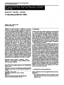
3 What is needed to define a UML Profile for Software Architecture Descriptions? In order to define a profile for Software Architecture Descriptions in UML, one needs to identify the key concepts that are required for software architecture descriptions and understand how those concepts are related. In the following, we present an example that introduces the architecture of a simple Video Surveillance System and highlights some software architecture elements. Connection point
Connection point
control data CameraDevice
Component
VideoControlStation
Component
Connector
Figure 1: Architectural Illustration of the Video Surveillance System
Figure 1 shows a very informal representation of the architecture of the Video Surveillance System (VSS). VSS consists of a set of video cameras that interact with a control station over a communication platform. The example illustrates two kinds of software architecture constructs: the components of the system and their interconnection realized by a connector. The boxes are used as graphical symbols for both kinds of constructs. They visually encapsulate their realizations, i.e., the pictures contained in the boxes.
3
The CameraDevice component abstracts a set of geographically distributed video cameras, whereas the VideoControlStation component abstracts the part of the system that remotely controls the cameras and continuously receives the video streams. The connector is an abstraction for the communication platform. It consists of two kinds of nested boxes that represent connection points and the protocol of interactions between these connection points, respectively. A connection point represents an interface to the connector a component can use. In order to be able to participate in a communication mediated by a connector, a component must implement this interface. The implementation might be in software or in hardware. For instance, in Figure 1, two circuit boards implement the interfaces with the camera device and the video control station. The protocol of interaction describes the way communication between connection points is performed. The cable in Figure1 shows the hardware part and the control/data box shows the software part of the implementation of the protocol of interaction. To distinguish between a software architecture, describing a family of similar systems, and one of its instantiations, i.e. an individual system architecture, we need the concept of architectural configuration. In our example, an architectural configuration is created by interconnecting specific instances of CameraDevice with a specific in stance of a VideoControlStation. In addition, many authors [1,2,8,9,10] have advocated the use of patterns in software architecture descriptions. For example, in configurations of the Video Surveillance System, the instances of VideoControlStation and CameraDevice will have to behave like "sink" or "client", and "source" or "server", respectively, when they consume and produce video streams, or provide and require services from each other. The software architecture of the Video Surveillance System is hence using the architectural styles known as client-server and pipe-and-filter styles [1,10]. All elements mentioned so far for describing software architectures are provided by current ADLs [6,8,9], but the resulting models do not integrate well with other artifacts resulting from the software development process. Because UML is a widely used notation in software development, the definition and use of a UML Profile for Software Architecture would yield software architecture models that integrate much better with other development artifacts. In addition to current ADLs, the UML Profile should also provide support for identifying and describing architectural viewpoints [13]. Unlike current ADLs, the UML Profile should be able to deal with various architectural views, a concept slightly different from a view as defined in standard UML. All the architectural terms introduced above are explained in the next section.
4 UML Extensions for Modeling Architectures The goal of this section is to present some extensions to the UML that define the software architecture abstractions introduced in the previous section. Therefore, we propose a notation and precise semantics for these abstractions, applying two mechanisms proposed by the OMG [12], which are referred to as "lightweight extension mechanism" and "heavyweight extension mechanism". A lightweight extension mechanism allows one to adapt the UML semantics without changing the UML meta-
4
model. It is supported by the UML through the provision of built-in extension mechanisms known as Tagged Values, Stereotypes, and Constraints. In contrast, a heavyweight extension mechanism allows one to adapt the UML semantics by extending the standard metamodel. In the following subsections, we make use of both extension mechanisms to propose a UML Profile for Software Architecture. A profile is "… a consistent definition context for elements such as, but not limited to, well formedness rules, tagged values, stereotypes, constraints, semantics expressed in natural language, extensions to the standard metamodel and transformation rules" [12]. First, we present our interpretation of the concepts of architectural viewpoints and architectural views proposed by the IEEE's Recommended Practice for Architectural Description (P1471) [13], then we apply a heavyweight extension mechanism for incorporating these concepts into the UML metamodel. Second, we use some lightweight extension mechanisms for specifying connectors, components, architectural patterns, and configurations of software architectures.
4.1
Architectural Viewpoints
The software architecture definition given in this paper, as well as the results of a large amount of research on ADLs, have been based on the assumption that software architecture is focussed on reasoning about structural issues at system-level [1,2,6,7,8,9]. We believe that focusing just on the structural issues does not cover all concerns of software architecture, since it is difficult or even impossible to cover all concerns of the stakeholders from just one perspective. Different stakeholders have different concerns relative to a system under development, and these concerns affect the system’s operation, as well as its architectural qualities, such as scalability, persistence, security, reliability, distribution and performance. Software architecture must address all the significant system-level properties or any desired combination of these properties that is of interest to any stakeholder. To achieve this, new mechanisms are needed to separate all architecturally important concerns. One way to separate architectural concerns is to describe software architecture from different perspectives or viewpoints. The concept of multiple viewpoints allows us to group different stakeholders' concerns into different sets of related kinds of concerns; each set represents a certain aspect of the system that can be "viewed" from a particular viewpoint. The notions of architectural views and viewpoints have been used in reference models such as the “4+1 View Model” 1 [16] and the ISO’s Reference Model for Open Distributed Processing (RM-ODP) [19]. Both reference models have a limited fixed number of views and viewpoints and do not allow to create new ones. We believe that such a fixed number of views and viewpoints is not sufficient for covering all aspects of software architecture. We use the terms architectural view and viewpoint as defined in the IEEE’s P1471. According to the P1471, an architectural viewpoint is "a specification of the conventions for constructing and using a view. A viewpoint acts as a pattern or template from which to develop individual views by establishing the purposes and audience for a 1
Rational Software Corporation is using the "4+1 View Model" as a reference model for their development methods, but it is not standardized.
5
view and the techniques for its creation and analysis". In what follows, we propose an interpretation of this definition providing a UML-based conceptual framework for architectural descriptions, which does not prescribe a limited number of architectural viewpoints and views. In this interpretation, an architectural viewpoint defines a particular perspective of a software architecture representation that allows the establis hment of rules, notations and a main view by which one or more architectural views are created, depicted, analyzed and managed. In a viewpoint definition, the rules determine the manner in which the concerns of the architect2 are represented in architectural views. These rules are expressed by means of notations that involve techniques for depicting architectural elements on a view, and they also describe the conventions that guide a projection of the main view onto particular views. The notations of a viewpoint describe the language elements that are needed for appropriately representing all the concerns of the software architect from the perspective defined by that viewpoint. The main view represents the primary focus of the architect from the particular perspective defined by that viewpoint. By convention, the name of the main view corresponds to the name of its viewpoint. Note that sometimes the model of the main view (most abstract model) can not be graphically described, e.g., a quality management viewpoint [21] will not have a corresponding model in the main view. Using the main view as the most abstract architectural view to be referred to for projections allows one to structure the system from a particular angle, yet focus on specific concerns.
Structural Viewpoint Structural View
Static View Configuration View
Enterprise Viewpoint
Behavioral View
Enterprise View
System under development
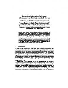
Figure 2: Example of the Relationship between Viewpoints and Views Figure 2 presents an example of the relationship between architectural viewpoints and views. In this Figure, we distinguish between two architectural viewpoints, the structural viewpoint and enterprise viewpoint. Each of them represents an abstraction mechanism allowing the system under development to be "viewed" from a particular angle. Each viewpoint defines a main view illustrating the primary focus of the archi2
In this UML-based conceptual framework, the concerns of the software architect from a specific viewpoint represent the concerns of the system's stakeholders involved in that viewpoint.
6
tect in that viewpoint. To describe distinct aspects of software architecture, the main view of a viewpoint needs to be projected onto different architectural views. This is shown by projecting the main view of the system from the structural viewpoint onto the static view, behavioral view and configuration view (more details in section 4.2). Note that main views, e.g. the enterprise view and the structural view, might overlap, and the same holds for architectural views. Behavioral Elements
Foundation
Software Architecture Profile
Model Management
Figure 3: Dependencies between the Software Architecture Profile and the UML Metamodel
To specify the software architecture profile, we use a heavyweight extension mechanism by adapting the UML metamodel. Figure 3 illustrates the relationships between the software architecture profile and the standard metamodel of the UML. The software architecture profile is represented by a UML package that defines the elements for describing software architectures explicitly. The Software Architecture Profile package depends on the Behavioral Elements package because it needs to extend, for example, the UML notion of collaboration to define complex connectors. Its dependence on the Model Management package is justified by using, for example, the subsystem concept that is required to define the general notion of a component. Figure 4 depicts a metamodel in terms of a UML class diagram that introduces the content of the Software Architecture Profile package. This metamodel represents a modified version of the conceptual model of the architectural description defined in the IEEE P1471. Basically, we adapted this model by adding the notion of main view. describedBy
ArchitecturalDescription 1 organizedBy
1
1
Architecture 1..*
selects
1..*
ArchitecturalView name purpose concerns elements
1
1..*
ArchitectureViewpoint
/conformsTo 1..* 1
1..*
Main View focus elements
isProjectedOnto
1 name defines addressableConcerns viewpointLanguage 1 1 constructionRules analyticTechniques
1 1..* ModelElement constituents (from Core)
consistOf 1..*
Figure 4: Extended P1471 Conceptual Model of Architectural Description
This conceptual framework is an interpretation of the IEEE’s recommendations for software architecture descriptions within a UML-based context. UML provides already a general notion of view, and discusses possible connections between views, i.e., the consistency of the elements used in different views [4]. R. Hilliard and others have stated that there are problems related to the use of multiple views in the field of software architecture [20,17]. The connection between UML models that describe different views helps to solve some of these problems. In this profile, the concepts of viewpoints and views are considered to be first-class citizens. We now present some examples of architectural viewpoints, showing how to describe the main view of a viewpoint in a concrete way. A typical example of an architectural viewpoint is the structural viewpoint that is addressed by almost every ADL.
7
Other possibilities for architectural viewpoints are, e.g., ODP viewpoints [19], requirements engineering viewpoint, quality management viewpoint [21], etc. Figure 5 shows the model of the structural view3 for the Video Surveillance System. This model reflects the main focus of the software architect when considering the system from the structural perspective. In this example, the model of the structural view is presented in terms of components and connectors, and constraints on these components and connectors. Thus, the structural view consists of two component types, CameraDevice and VideoControlStation, which are interconnected by the connector, VSConnector. For brevity we omit the discussion of architectural constraints. «archComponent » CameraDevice
«archComponent» VideoControlStation
VSConnector
Figure 5: Model of the Structural View for the Video Surveillance System.
A component type is defined by the UML stereotype «archComponent». Such a component type, similar to that defined by Miller et al. [23], is a subsystem, which has the properties of both a UML Class and a UML Package. The connector type is represented by a stereotype of Collaboration that contains a connector icon, shown by the black and white connected circles, in the upper right hand corner. As this connector type serves as the description of numerous kinds of component interactions (as mentioned in section 3), the VSConnector is considered to be a higherorder (or complex) connector. The notations and semantics of connectors, including higher-order connectors, are described in subsection 4.2.1.
4.2
Architectural Views
An architectural view is an abstraction mechanism. It is a particular way of looking at an architectural description that illustrates some concerns of the software architect from a specific perspective and suppresses details of implementation, algorithm, and data representation. According to our conceptual framework, an architectural view represents a projection of the main view of a system from a particular viewpoint. Such a projection allows the software architect to concentrate on the description of the system, taking into account some of the stakeholders' concerns and ignoring others. The above definition of the notion of architectural view is compatible with the UML notion of view. However, the latter is more general and does not distinguish between different levels of abstraction. For example, the UML static view can, on one hand, describe a conceptual analysis class model, with a class representing a domain concept, and on the other hand describe an implementation class model, with a class representing code. To give examples of architectural views, we will project the structural view of the Video Surveillance System. The result is three kinds of architectural views that describe the static structure, dynamic structure and configuration structure of the software architecture of the system. 3
According to the naming convention, the structural view is the main view of the structural viewpoint.
8
4.2.1 Static View To describe the static structure of the system, the software architect projects the structural view onto the static view. The elements in the model describing the static view are presented in terms of component types and connector types in the system, and constraints on these components and interconnections. In this view, a component represents an encapsulation unit for data and computation, called a computational component. Its stereotype is represented by the keyword «computational». A component type encapsulates the static structure of a computational component. It is specified as a set of interface elements that together define the component interface. A computational component communicates with other comp onents through its interface. Thus, each interface element defines a logical interaction point between the component and its environment. The concept of computational component used in this paper is similar to "computational objects" defined by the RM-ODP [19]. However, the approach we propose for specifying this concept is principally based on the notion of “capsule” introduced by B. Selic and J. Rumbaugh [11]. Like a capsule class, a computational component type defines additional class compartments that are labeled with the keywords operational, signal and stream. These compartments are used for the declaration of the interface elements. The keywords operational, signal and stream indicate the kinds of interface elements that can be supported or required by a computational component. Semantically, an interface element type is not equivalent to a UML interface, as it can be instantiated at runtime (as in ROOM [22]). Another alternative to represent a computational component consists in placing a computational icon (see icon on CameraDevice) in the upper right hand corner of the class name compartment. For the sake of clarity, we show both the stereotype and the icon on the elements in Figure 6. The type of an interface element is either operational, signal or stream. An operational interface element type describes a set of operations that can be required or provided by a specific component, whereas a signal interface element type specifies a set of signals that can be sent or received by a specific component. A stream interface element type specifies a set of quality of services to be guaranteed by data flow connections, as well as a collection of streams that can be consumed or produced by a specific comp onent. «operational»
« computational »
CamControl
CameraDevice
Provides start() stop() zoom() pan tilt Requires
Operational + /camControl
+ /camControl: CamControl
Signal
« stream »
« signal »
QualityOfService
Outgoing
Produces Incoming
Stream Consumes
Figure 6: Static structure of the computational component type CameraDevice.
Figure 6 shows an example of the static structure of a computational component type, called CameraDevice. The interface of the CameraDevice is specified by the CamControl, which is an interface element of type «operational». Accordingly, the CameraDevice provides a set of operations (such as start, zoom, and stop) that allows the
9
control station to remotely control a video camera implementing the CamControl. The composition relationship between CameraDevice and CamControl indicates that the interface element is an externally visible part of the component. The label (camControl) on the association end represents the public classifier role to be fulfilled by an instance of the CamControl, which is referred to as a port in the configuration view (see 4.2.3). The other two unnamed interface element types are not used in the example but show the graphical notations for stream and signal interface element types. A connector is an abstraction that explicitly represents a locus of definition for component interconnections and communication responsibilities. A connector type defines a pattern of interactions between two or more components. Like a connector type, a Collaboration in UML describes a pattern of interaction among a set of participants, which are usually instances of classes or data types. The structure of a Collaboration is defined by a collection of roles, called Classifier roles and Association roles. A Classifier role is a slot that describes the role played by a participant in the Collaboration, whereas an Association role describes the connection between two Classifier roles within the Collaboration [4]. The description of Collaboration often depends on the participants (objects and/or classes). However, in software architecture, it is important to be able to specify a connector independently of any of the components that may use it to communicate. To enable connector modeling in UML, we propose a stereotype of a Collaboration that allows us to separate the specification of connectors from that of the components. We define therefore the stereotype «connector» that specializes the Collaboration concept by hiding Classifier roles and introducing the notion of Connection role and Connection point. A connection role is a stereotype of an association role, a particular association, which describes the connection between two compatible connection points. A connection role extends an association role by defining some constraints (restrictions or semantic conditions) to be applied on the connection. These constraints should be fulfilled in any interaction mediated between the connection points. A connection role also allows one to describe a protocol of interactions, as shown in the behavioral view. A connection point is a concept that represents a connector interface. It is a kind of "association end role" that defines the participation of a component in a connector type. A connection point is specified in terms of messages or data flows that a participant component can exchange with others in interactions mediated by the connector. The benefit of this approach is that 1) it allows one to specify simple connector types and higher-order connector types using the same notation; 2) a simple connector type can define some architectural styles implicitly; 3) a higher-order connector type can be specified as a composition of simple connector types. The static structure of a simple connector type consists of two connection points and a connection role. A simple connector type can only mediate interactions between two components. For instance, one connection point could be seen as defining the participation of the client component, while the other defines the participation of the server component. In this case, a connector role defines the protocol of interactions between the client and the server and the constraints that are applied to both participants. The same reasoning could be used in the case of the pipe-and-filter style, with the difference that the connection role would define the properties of the pipe,
10
whereas the connection points would represent the participation of the filter comp onents. Connection point
Connection point
Classifier role
Classifier role Connection role
Figure 7: Static Structure of a Simple Connector type.
Figure 7 gives an overview of the static structure of a simple connector type. The white and the black circles are two connection points, conjugates of one another. We took the concept of “conjugated” elements from B. Selic et al. in [11] and [22]. Conjugated connection points are two connection points that are compatible but one is the inverse of the other. A higher-level connector type is a composition of two or more simple connector types. Figure 8 presents an example of the static structure of a higher-order connector type, the VSConnector. The labeled white circles on the border of the collaboration symbol represent the simple connector types that are combined to define the specification of the higher-order connector. In other words, each white circle is a shorthand representation of two conjugated connection points and one connection role. Accordingly, the VSConnector is presented as a composition of the following five simple connector types: VirtualDevice, StreamController, StreamEndPoint, VideoStream and StreamEndPointSignaling. «signal» VirtualDevice
«stream» VideoStream
«connector» VSConnector
«signal» StreamEndPointSignaling
«operational» StreamController
«signal» StreamEndPoint
Figure 8: Static Structure of the VSConnector. VirtualDevice defines all configuration related interactions that can take place between two compatible multimedia devices. It describes the sequence of alternating configuration signals that are exchanged between the interacting parties. StreamController mediates the interactions for initiating and finishing the negotiation procedure in point-to-point multimedia connections. It describes how to control and coordinate the connection activities that are particular to stream connections between multimedia devices. StreamEndPoint determines the interactions related to the control of individual flow endpoints composing a stream endpoint. It describes how to control and manage flow connections between multimedia devices. VideoStream defines a set of data flows, where each flow represents a continuous sequence of objects in a specific direction. It defines the continuous media transfer between components and describes the quality of service constraints that are related to it. StreamEndPointSignaling is needed to mediate a set of signals for the establishment and release of stream connections (in a nonsophisticated environment). An elaborated description of these five simple connector types is shown in Figure 9. In this figure, the keyword "Connector" and the scope operator "::" preceding the
11
name of the connection point type indicate that the connection point is defined within the scope of a connector. This allows one to differentiate between interface elements of components and connection points in connectors at the configuration level. A connection point can be a signal, a stream or an operational connection point. The form of communication supported by a simple connector type corresponds to the type of its connection points. Similarly, the higher-order connector type supports all the kinds of communication that are supported by its constituents. In Figure 8, for instance, the form of communication supported by the simple connector type VirtualDevice is signal. This is indicated by the corresponding stereotype «signal». Thus, we can see that the higher-order connector type VSConnector supports the mediation of streams, signals and operations. Like other constructs in the UML, the Object Constraint Language (OCL) can be used in the static view to define constraints on the components and connectors. «Connector::signal» VirtualDevice Outgoing setPeer ( ) setFormat () setDeviceParams ( ) modifyQoS ( ) configure () Incoming setPeer () setFormat () setDeviceParams ( ) modifyQoS ( ) configure ()
«Connector::signal» StreamEndPointSignaling Outgoing connectRequest() connectResponse ( ) Incoming connectIndication () connectConfim ()
«Connector::signal» StreamEndPoint Outgoing start ( ) stop () destroy () connect () requestConnection () modifyQoS ( ) disconnect () Incoming
«Connector::stream» VideoStream QualityOfService pictureQoS: VideoQoS soundQoS: AudioQoS flownum: NumberOfFlows Produces picture: VideoFlowType audio: AudioFlowType Consumes
«Connector::operational» StreamController Provides start () stop () modifyQoS () bindDevices () unbindDevices () destroy () Requires
Figure 9: Elaborated Simple Connector types composing the VSConnector.
4.2.2 Behavioral View The purpose of the behavioral view is to provide the part of the software architecture description that focuses on behavioral (or dynamic) properties of a system under development. To describe the behavioral structure of the system, the software architect makes a projection of the structural view onto the behavioral view. This projection allows the architect to separate the behavioral concerns of the system from all the others. The behavioral properties of the system are defined by the behavior of its computational component types and connector types, and the constraints on the elements describing that behavior. The behavioral structure of a computational component is defined by the specification of its interface protocol, the component interface protocol (CIP). The component interface protocol describes the allowable sequence of data flows, call events and signal events that a given component may be engaged in. A component interface protocol can be modeled as a composite state machine that contains the entire set of the protocol state machines of all the interface elements. An approach that can be used to specify operational interface elements has been proposed in [15]. Like for components, the behavioral structure of a connector is defined by using protocol state machines. To describe the behavior of a simple connector type, we specify the protocol of interactions of the connection role using a UML protocol state machine.
12
destroyed timeOut
Initial idle
request
destroy announcing
response
waitingFor Confirmation
«Connector::signal» StreamEndPointSignaling Outgoing connectRequest( ) connectResponse () Incoming connectIndication () connectConfim ()
timeOut
Figure 10: Representation of the StreamEndPointSignaling in the behavioral and static views. In the case of a higher-order connector type, a composite state machine will be used that contains the protocol state machines of each of the simple connector types composing it. Figure 10 shows an example of a protocol state machine that describes the behavior of the simple connector type StreamEndPointSignaling. It describes the allowable sequences of signal events that are related to the establishment and release of stream connections between two communicating components. According to the protocol that is shown in Figure 10, the initiating component must be in the state idle to send the connectRequest signal, which results in the request signal event. When the connectRequest signal arrives at the connection point on the site of the receiver, an indication signal event (entry event of announcing state, not shown) occurs. The receiver component gets a connectIndication signal announcing that a component wants to connect to it. Then the receiver component may send the connectResponse signal to tell whether it wants to accept or reject the pending connection request. During this period, the initiating component will be waiting for confirmation. If the connection request is accepted, the response signal event occurs at the connection point on the site of the initiating component. This results in the arrival of the connectConfirm signal at the interface of the component issuing the connection request. In both the announcing and waitingForConfirmation states, it is possible that the process restarts when the timeOut signal event occurs. In the waitingForConfirmation state, the connection is deleted when the destroy signal event occurs. Figure 10 also illustrates that views can be interdependent, e.g., the state machine models the behavior of the StreamEndPointSignaling connection point.
4.2.3 Configuration View The purpose of the configuration view is to offer a partial description of the software architecture of a system under development that focuses on a set of instances of the component and connector types defined in the previous architectural views. As in the other views, this projection allows the software architect to separate the configuration issues from all the other kinds of concerns. The elements that define the configuration structure are instances of computational component types and connector types, together with the constraints on these elements. A simple configuration structure can be described by using only simple connectors and two components, whereas a complex configuration structure requires the instantiation of a higher-level connector type and several component types. Thus, the interconnection of components using a composition of many simple connectors may be used to define the configuration structure of a complex system. To get different configurations of the same architecture, a higher-order connector type is instantiated in
13
different ways. In this case, some kind of configuration script may be needed for each particular configuration. The script defines which of the simple connector types of a higher-order connector type would be instantiated in a specific configuration. The instance of a simple connector type has two categories of elements: dynamic ports and a link between these ports, where each (base) port has a corresponding conjugate (symbolized by a '~'). A dynamic port is an instance of a connection point that is dynamically created (as part of the connector type instance) and attached to a component. To attach a dynamic port to a component means that the component has to provide a realization of the connection point. The link between the ports represents an instance of the connection role defined by the connector type. When a component type is instantiated, all of its interface element types are also instantiated. The instances of the interface element types are, in contrast to dynamic ports, called static ports. To differentiate dynamic ports from static ports, the stereotype of the connector type is prefixed with the keyword "Connector" («Connector::portname»), indicating that the port is an instance of a connection point. /camControl:VCamControl «computational»
/ vStream :VideoStream
/camDev:CameraDevice
«computational»
/vcs: VideoControlStation / vStream :VideoStream ~
:StreamEndPointSignaling
Legend:
:StreamEndPointSignaling ~
Base signal port
Base stream port
Base operational port
Conjugated signal port
Conjugated stream port
Conjugated operational port
Signal connector
Operational connector
Stream connector
Figure 11: Simple Configuration of the Video Surveillance System Figure 11 presents an example of configuration of the VSS that shows an instance of the VSConnector, CameraDevice and VideoControlStation. The stream port (black and white circles within a box) indicates that the stream communication is bi-directional. According to the configuration script used for this example, the instantiation of the VSConnector shown contains only the simple connector type instances StreamEndPointSignaling and VideoStream.
5 Summary and Future Work In this paper, we have argued for a UML profile for software architecture descriptions, which extends the standard UML by incorporating some key constructs found in current ADLs. For this purpose, we focused on a set of software architecture concepts, such as viewpoints, views, connectors, components and configurations. We illustrated also how they can be combined to describe different views that may represent together the software architecture of a system in UML. The resulting approach is an interpretation of the IEEE’s Recommended Practice for Architectural Description (P1471). We demonstrated it on a video surveillance system, which in particular highlighted the ability to describe the combination of three different types of communication: signal, operational and streaming protocols. Furthermore, we proposed an approach how to specify simple and complex connectors.
14
Though there are still many open issues, we hope that this paper is a first step in the right direction towards a UML profile for software architecture descriptions. In future work, we will refine the proposed UML profile, apply it to other examples and address some issues related to the support of Multi-Dimensional Separation of Concerns (MDSOC) in software architecture. Also, we will investigate the usefulness of Aspect-Oriented Programming techniques for implementing higher-order connectors. Finally, we will explore different ways to describe configuration scripts, and define constraints between simple connectors composing a complex connector.
6 References 1. 2. 3. 4. 5. 6. 7. 8.
9. 10. 11. 12. 13. 14.
15. 16. 17.
18. 19.
Shaw, M., Garlan, D.: Software Architecture - Perspectives on an Emerging Discipline. Prentice-Hall, New Jersey (1996). Bass, L., Clements, P., Kazman, R.: Software Architecture in Practice. Addison-Wesley (1998). Booch, G., et al.: The Unified Language Modeling User Guide. Addison-Wesley (1998). Rumbaugh, J., et al.: The Unified Language Modeling Reference Manual. Addison-Wesley (1999). The Unified Modeling Language Specification. Object Management Group (On-line at http://www.omg.org), Framingham, Mas. Garlan, D., Monroe, R. T. and Wile, D.: ACME: An Architecture Description Interchange Language. Proceedings of CASCON '97 (1997). Allen, R. J.: A Formal Approach to Software Architecture. Ph.D. Thesis, Carnegie Mellon University, School of Computer Science, available as TR# CMU-CS-97-144, May (1997). Medvidovic, N. and Taylor, R. N.: A Classification and Comparison Framework for Software Architecture Description Languages. IEEE Transactions on Software Engineering, Vol. 26, No.1, January 2000. Clements, P.: A Survey of Architecture Description Languages. 8 th International Workshop on Software Specification and Design, Germany, March, 1996. Buschmann, F., Meunier, R., Rohnert, H., Sommerlad, P., Stal M.: Pattern-Oriented Software Architecture – A System of Patterns. John Wiley and Sons Ltd (1996). Selic, B., Rumbaugh, J.: Using UML for Modeling Complex Real-Time Systems. ObjecTime, (1998). Object Management Group: Analysis and Design Platform Task Force White Paper on the Profile mechanism . Version 1.0. OMG Document ad/99-04-07, URL: www.omg.org. IEEE Architecture Working Group: Draft Recommended Practice for Architectural Description (Version 5). October (1999). Robbins, J. E., et al.: Integrating Architecture Description Languages with a Standard Design Method. In Proc. of the 20th Intl. Conf. on Software Engineering (ICSE'98), pp. 209-218 (1998). Sendall, S., Strohmeier, A.: From Use Case to System Operation Specifications. To be published in the UML'2000 Conf. Proc., Stuart Kent and Andy Evans (Ed.), LNCS (2000). Kruchten, P. B: The 4+1 view model of architecture. IEEE Software, 12(6):42-50, (1995). Le Métayer, D. and Périn M.: Multiple Views in Software Architecture. Position paper from the First Working IFIP Conference on Software Architecture WICSA1, San Antonio, (1999). Perry, D. E. and Wolf, A. L.: Foundations for the Study of Software Architecture. ACM SIGSOFT Software Engineering Notes, 17:4 (October 1992). ISO/IEC 10746-1/2/3. Reference Model for Open Distributed Processing – Part 1: Overview/Part2: Foundations/Part3: Archictecture. ISO/IEC (1995).
15
20. Hilliard R.: Views and Viewpoints in Software Systems Architecture. Position paper from the First Working IFIP Conference on Software Architecture WICSA1, San Antonio, (1999). 21. Sommerville et al. Managing Process Inconsistency Using Viewpoints. IEEE Transactions on Software Engineering, Vol. 25, No.6, November/December 1999. 22. Selic, B., Gullekson, G., Ward, P. T.: Real-Time Object-Oriented Modeling. Wiley, (1994). 23. Miller, J., Wirfs-Brock, R.: How Can a Subsystem Be Both a Package and a Classfier? 2 nd International ConferenceUML '99, The Unified Modeling Language: Beyond the Standard, USA, 1999.
16