UML PROFILE FOR ASPECT-ORIENTED SOFTWARE DEVELOPMENT Omar Aldawud
Tzilla Elrad
Atef Bader
Lucent Technologies
Illinois Institute of Technology
Lucent Technologies
Naperville, IL
Chicago, IL
Naperville, IL
[email protected]
[email protected]
[email protected]
1. INTRODUCTION ABSTRACT This paper’s position is that the time is ripe for initiating a proposal for an AOSD UML Profile. Some of the proposed Profile requirements are: (1) The Profile shall enable specifying, visualizing, and documenting the artifacts of software systems based on Aspect-Orientation. (2) The Profile shall be supported by UML (avoid “Heavy-weight” extension mechanisms), this allows a smooth integrating of existing CASE tools that support UML. (3) The Profile shall support the modular representation of crosscutting concern. And (4) the Profile shall not impose any behavioral implementation for AOSD, however it shall provide a complete set of model elements (or Stereotypes) that enable representing the semantics of the system based on Aspect-Orientation. AOSD Profile will set the stage for AOSD modeling, will enable capturing desired terminology of AOSD and will provide “native” support for AOSD in UML. Initial
research publications and workshops on UML for AOSD have set the stage for our proposal.1
1
This research is supported in part by NSF grant 557624 NSF ELRAD 41901 18 TE 02
AO technology is rooted back to the separation of concerns [10] by which different concerns of the software system can be designed and reasoned about in isolation from each other. The main theme of AOSD is the modular representation and weaving of crosscutting concerns. Recent work in AO design [[1],[3],[4],[5],[18],[29],[30],[31],[32],[33]] has demonstrated the need to deploy this technology early in the software life cycle in order to utilize the technology to its full potential. Once an initial decomposition of the problem identifies the software components and the corresponding aspectual properties that cut through these components, we would like to be able to express and model this initial decomposition in a formal way and carry it to the next phase of the development life cycle. Aspect-Oriented modeling should have the same relationship to AO Programming as Object-Oriented modeling has to OO Programming. Since UML is "the" standard modeling language for OO it is natural to use it (and perhaps extend it) for AO. Most of the research in AO modeling has taken this approach and this was also agreed upon in the workshops proceedings of the first AOSD conference [19]. In [1] we demonstrated that when aspects are identified at an early stage of the development life cycle, their design components are made more reusable, and automatic code generation is made possible for
1
AOP systems. In [4] it has been argued that capturing aspects at the design phase streamlines the process of AO development. In [5],[31] it is shown that applying AO design to the development life cycle can help maintain consistency between requirements, design, and code. We want to capture the aspects at a higher level, including their behavior, structure, and how they crosscut the core functional classes. From that design we want to be able to go to actual code in a traceable way. UML supports extensions mechanisms such as stereotypes, tagged values, and constraints [16] that allow tailoring it to fit the needs of a specific domain. A predefined set of extension mechanisms is called a Profile [11]. Researchers and practitioners have used these extension mechanisms packaged in a Profile to adopt UML to their particular domain. CORBA Profile [14], UML for Enterprise Application Integration [12], UML Profile for Enterprise Distributed Object Computing [13], and UML for Real Time systems [15] are examples of some proposed Profiles 2. In this paper we will use these extension mechanisms packaged in a UML Profile to tailor UML for AOSD. UML Profile for AOSD will provide conventions and guidelines for applying and specializing standard UML to the graphical notation for AOSD (Specialize UML meta-model for AOSD, and CASE tool support). The Profile will also set a common means of expressing AOSD artifacts visually for all AOSD stakeholders. In this Profile we argue that aspects must be modeled as first-class abstractions in order to promote reusability at the design phase. The proposed extension is supported by UML and thus can be easily integrated into existing CASE tools that support UML. We first proposed the Profile in [2], in this paper we report on our findings and experience with the Profile .
work has been presented in [20]. However, the presented work is focused on Aspect J, which was the original idea behind our work in [1] to prove the concept of a Profile and its applicability to existing CASE tools.
2. UML ARCHITECTURE UML [15] is the graphical notation that defines the semantics of the object meta-model (model of UML itself), and defines a notation for capturing and communicating object structure and behavior. In its meta-model architecture, UML supports extension mechanisms that allow tailoring it to fit the needs of a specific domain. These extension mechanisms are the means by which UML can adapt to new technologies, domains and methodologies. The Object Management Group (OMG) defines UML modeling language in a four-layer architecture as shown in Figure 1. Level 3 defines the metameta-model layer, which is defined by the Meta Object Facility (MOF). The UML meta-model specifies the modeling language; it is defined and standardized on top of the MOF in level 2. The AOSD and other Profiles should be defined at this level, since they are just a set of constraints on how UML is to be used when noting AOSD and other extended models. Level 1 defines the model layer, and the user object layer defines instances of the model at level 0. The standard meta-models represent areas under which specific domains require a specialization. In order to provide mechanisms for defining domain standards specializing of the standard meta-models, UML introduces the notion of a Profile. A UML Profile is a predefined set of extension mechanisms for a particular domain, technology, or methodology.
A subset implementation of the Profile has been applied as an add-in to Rational Rose and the 2
CORBA Profile has been adopted by OMG in October of 2000.
2
User Model Model Profiles (i.e. CORBA, PERSISTENT, AOSD,etc.)
Meta-Model Meta-Meta-Model Figure 1 - UML Architecture
2.1 UML Extension Mechanisms Extension mechanisms [16] are the means for extending UML to support a new technology. They are stereotypes, tagged values and constraints. •
Stereotypes are used to introduce a new type of model element as an extension or a classification of existing base element (i.e. as a classification of class). The stereotype concept allows the extended element to “behave as if it was instantiated from the meta-model construct”.
•
Tagged values specify keyword-value pairs of model elements to indicate a new property for existing UML model element or they can be applied to stereotypes.
•
Constraints are a set of wellformedness rules expressed in OCL or natural language. Constraints are the means by which new semantics can be introduced to UML.
2.1.1 UML Profiles A UML Profile [11] is a predefined set of extension mechanisms. UML Profile allows the stakeholders of a certain domain to express the semantics of their systems using a well-defined set of extensions. The Profile does not extend UML by adding a new concept. Instead, it provides connections for applying and specializing UML to a specific domain. It’s a mandatory requirement on any Profile that once the Profile is applied the resulting notation shall adhere to the syntax and semantics of UML. In other words, the Profile shall not break existing UML modeling principles. For that reason we did not find it necessary to add a new fundamental modeling concept to UML for AOSD, thus avoided extending UML via “heavyweight” extension mechanisms. There have been many UML Profiles proposed to OMG, UML Profile for real time systems UMLRT [15] is a UML extension to support Real Time intensive application. The Profile introduces the notions capsules, ports, connectors, protocols, and protocol role to UM L. UML Profile for CORBA [14] provides a standard means for expressing the semantics of CORBA IDL using UML artifacts, which enable expressing these artifacts with UML tools. In [22] a UML Profile that extends the existing class
3
diagram definition to support persistence modeling has been proposed. Primary key, secondary key, table, file are examples of stereotypes proposed in this Profile. In the following section we show our proposed extension to UML packaged in a UML Profile to support AOSD. Our proposed Profile introduces basic AOSD terminology to UML to enable the visual representations of AOSD systems in the design models.
3. UML PROFILE FOR AOSD The traditional approach to represent AOSD system via UML notation is to model aspects as a Classifier and then stereotypes the classifier to indicate whether it represents a crosscutting concern, a composition or a binding operation. Although this approach is practical, since stereotype is an official UML extension mechanism, there has been no standard set for extensions of UML to accommodate the needs for Aspect-Oriented Software Development.
system, it’s essential that this Profile address AOSD from all angles, and try as much as possible to satisfy all AOSD methods (Composition Filters, Frameworks, Aspect J, Hyper J, etc.). We need to create a set of extensions (stereotypes, tagged values, and constraints) to support AOSD and not a particular implementation of AOSD. We believe that the extension mechanisms are capable of adapting UML semantics to express AOSD terminology without changing the UML meta-model itself.
3.1 General Architecture Figure 2 shows the relationship of the AOSD Profile and the core package elements defined in the UML meta-model. The AOSD Profile extends elements defined in the UML metamodel (Model Element) by defining stereotypes. Extension mechanisms are based mainly on the concept of stereotype, which provides a way of classifying elements so that they behave as if they were instances of the new meta-model.
Since AOSD Profile is a mean for all AOSD steak holders to express the semantics of their
Stereotype
Model Element 0..*
Name Space
0..*
AOSD Profile
Package
Model
Figure 2- Profile General Architecture
4
In this Profile, the package structure is used exactly as it is defined in UML. Packages provide hierarchical name space in which to define components and where no semantics are implied [11]. Elements defined under the AOSD Profile will be placed in a Profile package that
extend the meta-class package to ensure that each element is unique within its scope. Figure 3 shows the AOSD Profile package notation. The specifications for the AOSD Profile are as follows:
AOSD Profile Specification Profile Name: Aspect Oriented Software Development Version: 1.0 Reference Meta-model: UML meta-model. Parent Profile: Meta Class Package Description: The AOSD Profile extends UML to support AO terminology.
Figure 3- AOSD Profile Package Notation
3.2 Modeling Concerns
Crosscutting
AOP [8] provides mechanisms for decomposing a problem into functional components and aspectual components called aspects. Aspects are concerns that cut across the core functional components. Some examples of aspects are: synchronization, scheduling, logging, security and fault tolerance. AOP attempts to modularize
aspects and uses the weaving mechanism to merge aspects with their perspective core functional components. The set of stereotypes for the Profile shall allow the modularization and composition of aspects and core classes. The core classes will be used as defined in UML core model elements. Aspects and corresponding associations will extend these model elements to allow this formalism (modularization and composition).
5
The Profile shall be capable of expressing aspects, core functional classes, and the associations between themselves and each other. The Profile shall also be capable of describing the structure and the behavior of those elements. To satisfy these requirements, UML can be extended by introducing a new stereotype called 3. The is a stereotype for the base class that is part of the element as shown in Figure 4. The stereotype will be used to model units of crosscutting concerns. When defining as a stereotype of the classifier , it is guaranteed that the behaves the same way as if it was created as an instance of . The newly constructed stereotype becomes a model element and can participate in the same relationships as a model element (i.e. dependency relationship, inheritance, etc.). This formalism will enable aspects to behave as “first-class citizens” which will ultimately enhance reusability of aspects. The aspect Stereotype specification is listed in Table 1.
3.2.1 Aspect Classifications Aspect semantics may vary depending on the role they play and the impact they have on the core functional classes. In this Profile, we would like to give general classifications of aspects. We found that aspect services could be classified as synchronous or asynchronous. Synchronous aspects usually control the behavior of classes. For example, in the bounded buffer problem, the synchronization aspect control access to the bounded buffer by intercepting requests to the buffer class. Asynchronous aspects on the other hand have no impact on the core classes, they usually perform a task and terminate without impacting the core class. For example the Error handler aspect presented in [1] displays error messages whenever they occur without any implication on the invoking class. The Logging aspect is another example of asynchronous aspect, this aspect logs events again whiteout any interruption to core classes behavior. In our Profile, we extend UML by introducing a Boolean tagged value for this classification {synchronous}. If the {synchronous} tagged value is set for a certain aspect, then Preactivation and Postactivation operations must be defined for that aspect. The specifications of the {synchronous} tagged value and the stereotype are shown in Table 1.
Figure 4- Aspect Stereotype 3
We first introduced the stereotype in [2]
6
Table 1- Aspect Stereotype Specification
Name
Base
Semantics
Related Constraints
Meta-class
{Synchronous}
Class
Association
Well-formedness rules/OCL The (1) is a class that represents an abstraction of (2) crosscutting concern and is used to model units of crosscutting concerns.
An aspect has to associate with a class or other aspects Aspects can communicate with classes with whom they are associated via dependency relationship which ultimately describe the composition of aspects and core classes.
The (1) The {synchronous} tagged value {synchronous} shall be used within the AOSD tagged value is package and shall only be used when the associated with aspects. aspect impacts the functionality (2) If the {synchronous} tagged value is set for a certain aspect of the core class then Preactivation and (i.e. Postactivation operations must Synchronization be defined for that aspect. aspect) OCL Context at: SynchronousAspect at.oclIsKindOf(Aspect) & at.oclIsTypeOf (synchronous) implies at.operation è forAll (o | at.contect.operation è exists (op | o.operation.name = Preactivation))
3.2.2 Associations Relationships When modeling for AOSD systems, a model should consist of two views, the core functional view and the aspectual view. In order to link these views together we need to construct relationship stereotypes (dependency, association, etc.). In its generic format, an aspect code crosscuts the core functionality of the
system and at some point this code must be woven with the core functionality. In this Profile, we introduce a generic stereotype to connect both views of the system and to add semantics to enable the weaving process. The specifications of the stereotype, the Preactivation and Postactivation operations are outlined in Table 2 below.
7
Table 2- crosscut Stereotype Specification
Name
Base Metaclass Association
Semantics
Related Constraints Well-formedness rules
The (1) stereotype will be Used to model cross-cutting relationships where the aspect code cross-cut the core functional (2) components
A association is only valid between aspects and between aspects and classes in the class diagram of the core functional components. Preactivation and Postactivation shall be defined for each association if aspect is {synchronous}.
OCL Context cc: crosscutAssoc. cc.oclIsKindOf(crosscut) implies cc.crosscut.Aspect.allAttributes èexists (forAll (o | cc.contect.operation è exists (op | o.operation.name = Preactivation)) (3)
Preactivation shall evaluate to true before Postactivation can be executed.
(4)
A class can be associated with one or more aspects.
(5)
Each aspect in the class diagram must be associated with at least one core functional class.
Operation
(1)
If the {synchronous} tagged value is set to TRUE for an aspect, then the Preactivation operation must exist for that aspect.
Operation
(1)
If the {synchronous} tagged value is set to TRUE for an aspect, then the Postactivation operation must exist for that aspect.
8
Note that by not specifying the synchronous tagged value for an aspect does not imply any default value. It simply means that the crosscutting relationship is not tied to any condition and the semantics of weaving will be provided in the dynamics of the system. This formalism should make the Profile compatible with different AOSD approaches (i.e. frameworks approaches, composition filters, etc.)
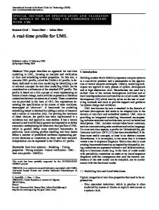
3.3 The Bounded Buffer Example To illustrate the practicality of the AOSD Profile, we apply it on the design and development of the bounded-buffer example. In summary, the buffer has a limited capacity and can handle multiple read requests concurrently, while queuing all write requests. Write requests should block all other services; the blocked service will be queued until the buffer is done writing. The synchronization and scheduling requirement crosscut the core functionality of the bounded buffer. The main synchronization requirements control access to the bounded buffer. For example we shall allow only the put method to proceed when the buffer is in EMPTY state. Either put or get can be issued when the buffer is in PARTIAL state. We shall allow only get when the buffer is in FULL state. On the other hand, the main scheduling requirements may impose certain access requirements on the system. For example, only one writer can access the system at a certain time, or more than one reader can access the system at a certain time. Synchronization constraints and scheduling specifications are the main crosscutting requirements (aspects) that
influence the execution of the invoked methods based on the object’s state. The synchronization and scheduling requirements can be modeled as aspects using the stereotype. These requirements the main bounded buffer class. The and buffer class can be statically weaved using the Profile artifacts as shown in the Object Diagram in Figure 5.
3.4 Structural Description Using Class Diagrams UML Class diagrams can be used to describe the static structure of the system (classes and aspects) and define the static relationships between these objects. Each class and aspect in the class diagram defines its own static structure including attributes, methods and interfaces. The lines between classes denote association relationships. Figure 5 shows the object diagram for the bounded buffer system. In Figure 5 both the Synchronization and Scheduling aspects are tagged with the Boolean tagged value {synchronous} and thus they must define the Preactivation and Postactivation operations (this formalism is shown by double arrow from/to the Buffer class to/from the Synchronization and Scheduling aspects). The Error aspect on the other hand is tagged with the Boolean tagged value {asynchronous} which will not require the definition of Preactivation and Postactivation operations (this formalism is shown by a directed arrow from the Buffer class to the Error Aspect). Note that the association is valid between aspects and between aspects and classes.
9
Figure 5- Bounded Buffer Object Diagram using the AOSD Profile
3.5 Dynamic Behavior
infrastructure to support all other behavioral packages.
The UML behavioral Package [15] shown in Figure 6 is composed of 4 major packages: Collaboration, Use Case, State Machine, and Activity Graphs Package. All packages are inherited from the Common Behavior Package, which specifies the core concepts required for describing a behavior, and it provides the
We don’t believe that the Profile shall dictate a specific behavioral package for AOSD. In the following subsections we will briefly describe the Collaboration and the Statemachine packages and we will outline how each can be used to describe the behavior of the system as a whole and the behavior of the individual aspects and classes.
10
Figure 6- UML Behavioral Package
3.5.1 Collaboration Diagrams A Collaboration Diagram describes how classes (classifiers) and their association are to be used in a accomplishing a particular task, in other words it defines a set of roles to be played by instances and links. Collaboration shows one or more roles, and the roles’ associations. Each role must be bound to a particular class that can support the operation required of the role. At the specification level, the collaboration diagram shows classifier roles and association roles. A Classifier role is a set of features required by the collaboration. Classifier roles for core classes implement the core features required by the system. Classifier roles for aspects are services required by the core classes which are otherwise tangled with the roles of the core functional features. Association role is a usage of an association required in collaboration. Association end role defines the endpoint of an association as used in the collaboration. The association role could be realized via the composition rules and could be associated with Preactivation and the association end role can be associated with a Postactivation.
Approaches presented in [29], [30], and [31] addresses representing AOSD systems in this fashion.
3.5.2 Statecharts UML adopted David Harel's statecharts [6] for the intra-object behavior modeling. Statecharts is a "behavioral" language for the specification of real-time, event driven, and reactive systems. States in a statechart are "conditions of existence" that "persist" for a significant period of time [7]. Events trigger transitions from one state to another. They may be guarded by conditions, which must evaluate to "true" before transitioning to the next state. Actions can occur as the result of a state transition. The statechart model can be used to support AOSD by extracting the hardwiring of conditions to transitions. In this Profile, we propose using statecharts to describe the behavior of aspects and objects because (1) they provide a rich set of semantics that are suitable for crosscutting behavior. (2) We assume a finite set of states, which will reduce the complexity of the system [6]. And (3) modeling with statecharts results in full behavioral specifications [6] this enables semantics preserving transformation between the
11
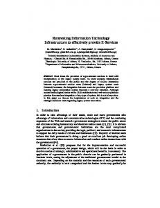
design and implementation and hence enables automatic code generation. In [1] we proposed a methodology for aspectoriented modeling based on advanced artifacts of statecharts. We have identified the main components and the corresponding crosscutting components at the design phase and introduced mechanisms to weave them4. The behavior of aspects and classes can be bound with a statechart, which could specify the mechanics for weaving aspects into classes. Figure 7 below shows this formalism. Since attaching conditions to transitions in a statechart would ultimately result in design and code tangling in [1] we extended the statechart model to remove hard wiring of conditions to transactions. We extracted these conditions from the main functionalities of the system and modeled them as autonomous pieces of behavior (aspects). By doing so, we show that the main functionalities (design and the associated code) of the system is not tangled with the associated aspects.
4. RELATED WORK AND POOSIBLE ADDITIONS TO THE PROFILE In this section we would like to outline the main AOSD modeling techniques presented so far and from each we could incorporate additions to the profile as proposed by each approach. For space and time reasons we will only study the Aspect Oriented Design Model (AODM) [30], and the Composition Pattern (Theme/UML) [31] in sections 4.1, and 4.2, respectively.
4.1 Aspect Oriented Design Model (AODM) [30] Stein et. al. proposed a UML based design language to support Aspect J [30]. The approach 4
We don’t intend on imposing our methodology or any other methodology to be used in conjunction with this profile.
introduces basic Aspect J constructs to UML via UML’s extension mechanisms presented earlier. Despite the fact that this approach is aimed at a particular implementation of AOSD, the presented extensions align well with the Profile. However, as stated earlier the Profile will remain applicable to all implementations of AOSD. The set of stereotypes presented by this approach and the associated Aspect J construct are shown in Table 3.
4.2 Composition (Theme/UML) [31]
Pattern
Clarke et. al. introduced a profound modeling approach based on UML in [5],[31]. The approach extends UML with Compositions Patterns. CPs are based on the subject-oriented [25] design principles, and are viewed in this approach as UML templates for UML packages. Clarke’s approach decomposes model elements in one notation (i.e. package) and then recomposes them with other. The decompositions proposed should be based on “features and capabilities”. Doing so, scattered requirements could be localized within a package, which could be weaved latter with other design models using composition relationships between them. The complete set of extensions to support this formalism can be found in [31]. Clarke’s et. al. work should ultimately be incorporated in the Profile and is left for the future work.
5. IMPLEMENTATIONS FUTURE DIRECTIONS
AND
Our initial research work presented in [2] has motivated many research groups to start investigating the practicality of the Profile. The initial assessment of the Profile has been developed in [20] using Rational Rose Extensibility Interface package. Since the initial Profile was aimed at the Aspect J model the team has to introduce new tagged values to satisfy the main concepts of Aspect J. For example, the Operation model element has been extended to support the advice formalism by introducing the , , , , and Stereotypes. Rose script language has been used to generate the Aspect J skeleton. As we stated in our introductory remarks, the Profile should not be aimed at an implementation of AOSD, rather it shall accommodate all
implementations of AOSD. Future directions of the Profile should focus on that. We will be conducting experiments with the Hyper J [23], Composition Filters [21], Reflection and metmodel protocol [24] and other AOSD techniques.
Figure 7- Bounding Aspects and Classes to a Statechart
Table 3- ADOM Stereotypes for Aspect J Aspect J Construct
AODM representation
Description
Aspect class
from class.
stereotype
We have already added the stereotype to the list of extensions.
Join Points
stereotype from operation model element.
A link could be viewed as a “principle points in the dynamic execution of a program” (same semantics as Aspect J).
“pseudo” stereotype from operation model element.
Links represent communications connections between two instances, and since links don’t dispatch events, the “pseudo” invocation stereotype .
13
“pseudo” invocation stereotype . Pointcut
stereotype form operation model element.
Same semantics as Aspect J.
must be implemented by methods of a special stereotype that equip the meta-class with additional property .
Advice
Is a feature of the aspect classifier.
Introduction
a stereotype of collaboration templates.
To capture introduction.
the
semantics
of
an
6. CONCLUSION
[3].
Aspect-oriented programming is becoming a maturing programming paradigm, and we argue that the AOSD community is ready to think about moving to formal modeling of AOSD Systems. A UML Profile for AOSD will be one more step in closing the gap between Object Oriented and Aspect Oriented design tools. There are still basic issues to be resolved. Collective efforts for the requirements and constraints for such undertake would help to achieve this goal. For this Profile to be complete, it is necessary that all AOSD researchers and AOSD user community participate in defining it.
Omar Aldawud, Tzilla Elrad, Atef Bader , "Aspect-Oriented Modeling to Automate the Implementation and Validation of Concurrent Software Systems", SIVOES'2001 Workshop, ECOOP 2001. http://wooddes.intranet.gr/ecoop2001/sivo es2001.htm
[4].
J. Suzuki, Y. Yamamotto , "Extending UML with Aspects:Aspect Support in the design phase"3 rd AOP Workshop at ECOOP 1999.
[5].
Patterns: An Approach to Designing Reusable Aspects"", Proceedings of the 23rd International Conference on Software Engineering (ICSE 2001). P 5-14.
7. REFERENCES [1].
[2].
S. Clarket, R.J. Walker, "Composition
Tzilla Elrad, Omar Aldawud, Atef Bader. “Aspect Oriented Modeling – Bridging the Gap Between Design and Implementation”. Proceedings of the First ACM SIGPLAN/SIGSOFT International Conference on Generative Programming and Component Engineering (GPCE 2002). October 6–8, 2002 Pittsburgh, PA, USA. PG 189-202.
[6].
David Harel "Statecharts": a visual formalism for complex systems, "Science of Computer Programming. Vol. 8 (1987),P. 231-274.
[7].
Bruce Powel Douglass, "Real-Time UML: Developing efficient Objects For Embedded Systems", Addison-Wesley, 1998.
Omar Aldawud, Tzilla Elrad, Atef Bader. “A UML Profile for Aspect Oriented Programming”. Workshop on Aspect Orientation. OOPSLA 2001. Tampa, Florida.
[8].
G. Kiczales, "An Overview of AspectJ", in proceedings of 15th ECOOP, 2001.
[9].
T. Elrad, M. Aksit, G. Kiczales, K. Lieberherr, and Harold Ossher, “Discussing
Aspects
Of
AOP”.
14
Communication of the ACM October 2001/Vol. 44, No. 10 P 33-38.
Communication of the ACM October 2001/Vol. 44, No. 10 P 51-57.
[10]. H. Ossher, M. Kaplan, W. Harrison, A. Katz, and V. Kruskal, "Subject-Oriented Composition Rules.," in Object-Oriented Programming Systems, Languages and Applications Conference, in Special Issue of SIGPLAN Notices, Austin, Texas, October 1995, pp. 235--250, ACM Press.
[22]. Scott Ambler “Persistence Modeling in the UML”. Published in Aug 1999 issue of Software Development. http://www.sdmagazine.com
[11]. OMG Document ad/99-04-07 April 1999. “White Paper on the Profile Mechanism” [12]. OMG Document ad/2001-09-17. “UML for Enterprise Application Integration “ [13]. OMG Document ad/2001-06-09. “UML Profile for Enterprise Distributed Object Computing” [14]. OMG Document ad/???. “UML Profile for CORBA specifications” [15]. OMG Document ad/97-08-03.”UML Syntax and Semantics guide”. http://www.rational.com/uml [16]. Sinan Si Alhir. “Extending UML”. Distributed Computing, 1998. PG. 28-32. [17]. Theme/UML. Extending Standard UML with model composition semantics. http://www.dsg.tcd.ir/~sclarke/ThemeUM L [18]. J. Gray, T. Bapty, S. Neema, and J. Tuck, "Handling Cross Cutting Constraints In Domain-Specific Modeling", Communication of the ACM October 2001/Vol. 44, No. 10 P 87-93. [19]. AOSD 2002 http://www.aosd.net
Proceedings.
[20]. Hoda Hosny, Amir Zeid, and Aida Zakaria. “A UML Extension for Modeling AO Systems”. AO Modeling with UML Workshop. UML 2002. Germany. [21].
Lodewijk Bergmans and Mehmet Aksit, “Composing Cross Cutting Concerns Using Composition Filters”,
[23].
Harold Ossher, Peri Tarr, Vincent Kruskal, “Hyper/JTM: Supporting Decomposition, Integration, and Evolution of Java TM Software”. OOPSAL 2001 proceddings.
[24]. Gregory
T. Sullivan, “Aspect -Oriented Programming Using Refelection And MetaObject Protocols”, Communication of the ACM October 2001/Vol. 44, No. 10 P 95-97.
[25]. Harrison, W. and Ossher, H. SubjectOriented Programming (A Critique of Pure Objects). Proc. OOPSLA ’93. ACM SIGPLAN Notices 28 (10), October 1993, pp. 411–428. [26]. Aksit M. and Tekinerdogan B. Solving the modeling problems of object-oriented languages by composing multiple aspects using composition filters. AOP '98 workshop position paper, 1998. http://wwwtrese.cs.utwente.nl/Docs/Trese papers/FilterAspects.html. [27]. Sutton Jr., S. M. Early-Stage Concern Modeling. Workshop on Early Aspects: Aspect-Oriented Requirements Engineering and Architecture Design, 1st International Conference on AspectOriented Software Development, Enschede, The Netherlands, April, 2002. [28]. Stanley M. Sutton Jr., Peri Tarr. “AspectOriented Design Needs Concern Modeling” OOPSLA 2001, Workshop on Advanced Separation of Concerns. Tampa, FL. [29]. Wai-Ming Ho, Jean-Marc Jezquel, Francois Pennaneac’h and Noel Plozeau. “A toolkit for Weaving Aspect Oriented UML Designs”. Proceedings of the 1st International Conference on AOSD.
15
Enschede, the Netherlands April 2002. PG99-105. [30]. Dominik Stein, Stefan Hanenberg, and Rainer Unland. “A UML-based AspectOriented Design Notation For AspectJ”. Proceedings of the 1st International Conference on AOSD. Enschede, the Netherlands April 2002. PG106-112. [31]. Siobhan Clarke. “Extending standard UML with model composition semantics”. Science of Computing Programming, 2002. [32]. Constantinos A. Constantinides, Tzilla Elrad and Mohamed Fayad. “Extending the object model to provide explicit support for crosscutting concerns”. International Journal of Software Practice and Experience, Volume 32, Issue 7, pages 703-734, June 2002. [33]. Constantinos A. Constantinides, Atef Bader, Tzilla Elrad, Mohamed Fayad, Paniti Netinant. Designing an AspectOriented Framework in an ObjectOriented Environment. In ACM Computing Surveys Symposium on Application Frameworks, M.E. Fay ad, Editor, Vol. 32, No. 1, March 2000.
16