Towards an Interoperability Framework for ModelDriven Development of Software Systems Brian Elvesæter1, Axel Hahn2, Arne-Jørgen Berre1, Tor Neple1 1
SINTEF ICT, P. O. Box 124 Blindern, N-0314 Oslo, Norway {brian.elvesater, arne.j.berre, tor.neple}@sintef.no 2 Wirtschaftsinformatik Universität Oldenburg, D-26111 Oldenburg, Germany
[email protected]
Abstract. This paper presents an interoperability framework for enterprise applications and software systems. The framework provides a foundation for model-driven development of software systems supporting the business interoperability needs of an enterprise. This is achieved through a set of reference models that addresses interoperability issues for conceptual integration, technical integration and applicative integration of software systems.
1 Introduction Enterprises today face many challenges related to lack of interoperability. Enterprise applications and software systems need to be interoperable in order to achieve seamless business across organisational boundaries and thus realise virtual networked organisations. IEEE [1] defines interoperability as “the ability of two or more systems or components to exchange information and to use the information that has been exchanged”. Model-driven development (MDD), and in particular OMG’s Model-Driven Architecture® (MDA®1) [2], is emerging as the state of practice for developing modern enterprise applications and software systems. The MDD paradigm provides us with a better way of addressing and solving interoperability issues compared to earlier nonmodelling approaches. However, developing correct and useful models to address interoperability is not an easy task. We believe that there is a need for an interoperability framework that provides guidance on how MDD should be applied to address interoperability. In this paper we present initial results from ATHENA [3] and INTEROP [4] in defining an interoperability framework for model-driven development of enterprise applications and software systems. The framework provides a foundation, consisting of a set of reference models, for how to apply MDD in software engineering disciplines in order to support the business interoperability needs of an enterprise.
1
Model Driven Architecture® and MDA® are registered trademarks of the Object Management Group
The paper is structured as follows: In section 2 we provide some background information. In section 3, the main body of this paper, we present the interoperability framework and its reference models for integration. In section 4 we discuss the usage of the reference models in an example scenario focusing on inventory replenishment. In section 5 we describe some related work. Conclusions and future work are presented in section 6.
2 Background We use the term model-driven development (MDD) to refer to model-driven systems development in a broad sense. The OMG MDA can be seen as a specific implementation of MDD with respect to software systems development. However, while the OMG MDA is heavily focused on software integration technologies, we see MDD as a new architectural approach for developing software systems based on requirements derived from enterprise and business models. Interoperability solutions should be driven by business needs first and software solutions second. Model-driven development in our view represents a business-driven approach to software systems development that starts with a computation independent model (CIM) describing the business context and business requirements. The CIM is refined to a platform independent model (PIM) which specifies services and interfaces that the software systems must provide to the business, independent of software technology platforms. The PIM is further refined to a platform specific model (PSM) which describes the realisation of the software systems with respect to the chosen software technology platforms. In addition to the business-driven approach, a model-driven framework should also address how to integrate and modernise existing legacy systems according to new business needs. This approach is known as architecture-driven modernisation (ADM) in the OMG. In order to structure the various models developed and used within an enterprise we adopt the recommendations of IEEE 1471 [5] which provide a terminology for structuring descriptions of systems according to viewpoints. Viewpoints help to separate the specification into views that address different areas of concern for different stakeholders. A view can be represented by a set of visual models expressed using a modelling language such as UML [6-8]. The interoperability framework described in this paper adopts the following terms from IEEE 1471 standard: − System: A collection of components organised to accomplish a specific function or set of functions. − Stakeholder: An individual, team, or organisation (or classes thereof) with interests in, or concerns relative to, a system. − Concern: Those interests which pertain to the system's development, its operation or any other aspects that are critical or otherwise important to one or more stakeholders. (In this paper we will also use the term aspect as a synonym for concern.) − View: A representation of the whole system from the perspective of a related set of concerns.
− Viewpoint: A specification of the conventions for constructing and using a view. A pattern or template from which to develop individual views by establishing the purposes and audience for a view and the techniques for its creation and analysis. − Model: A representation of an entity in the real world.
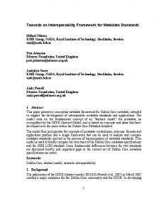
3 Interoperability Framework The interoperability framework presented in this paper is designed to fulfil these design rationales: − Identification of interoperability issues related to software models, using a holistic approach where software architectures and enterprise architectures can be related. − Identification of the relevant software architecture components, and explaining the relationships between these components. − Integration of model-driven software development processes. − Structuring of software technologies, frameworks and methodologies which can be found today. The interoperability framework itself is structured according to the three main integration areas defined in ATHENA [3]: 1. Conceptual integration which focuses on concepts, meta-models, languages and model relationships. It provides us with a foundation for systemising various aspects of software model interoperability. 2. Technical integration which focuses on the software development and execution environments. It provides us with development tools for developing software models and execution platforms for executing software models. 3. Applicative integration which focuses on methodologies, standards and domain models. It provides us with guidelines, principles and patterns that can be used to solve software interoperability issues. For each of these three areas we developed a reference model to describe and support the application of model-driven development of software systems. 3.1 Reference Model for Conceptual Integration The reference model for conceptual integration has been developed from a MDD point of view focusing on the enterprise applications and software system. A computation independent model (CIM) corresponds to a view defined by a computation independent viewpoint. It describes the business context and business requirements for the software system(s) under consideration. A platform independent model (PIM) corresponds to a view defined by a platform independent viewpoint. It describes software specifications independent of execution platforms such as WebService, J2EE, .net, agents and P2P technologies. A platform specific model (PSM) corresponds to a view defined by a platform specific viewpoint. It describes the realisation
of software systems in the chosen set of execution platforms. Figure 1 shows this relationship with respect to an enterprise system, where the CIM is embedded within the enterprise, the PIM is embedded within a computational system, and the PSM is embedded within an execution platform, which itself is embedded within the computational system. The figure also shows how the MDA and ADM could be perceived as a “top-down” and a “bottom-up” approach to software development and integration. The models at the various levels may be semantically annotated using ontologies which help to achieve mutual understanding on all levels. The use of reference ontology will also aid us in doing model transformations and mappings between and across the three model levels. We also see the usage of interoperability patterns for horizontal and vertical integration. Models are used to describe different concerns of a software system. We have identified four categories of system aspects where specific software interoperability issues can be addressed by conceptual integration. 1. Service aspects: Services are an abstraction and an encapsulation of the functionality provided by an autonomous entity, e.g. a software component. Services are typically provided through well-defined interfaces or contracts that specify their usage and behaviour. 2. Information aspects: Information aspects are related to the messages or structures exchanged, processed and stored by software systems or software components. Business concepts are represented in software as information messages or structures that are provided or required by services and processes. 3. Process aspects: Processes describe sequencing of work in terms of actions, control flows, information flows, interactions, protocols, etc. They can be applied to business aspects (e.g. workflow management) as well as technical aspects (e.g. communication protocols). 4. Non-functional aspects: Extra-functional qualities that can be applied to services, information and processes. These four aspects can be addressed at all three CIM, PIM and PSM levels. Specific concerns regarding them can be made explicitly visible through visual models defined by viewpoints used by different stakeholders within an enterprise. Other categories of aspects may be introduced, but we feel that the four identified here will provide a good baseline for discussing conceptual integration. All of the elements discussed above are integrated into figure 1 where we look at horizontal and vertical integration between two enterprise systems A and B. The same principles could of course be applied when addressing integration between multiple enterprise systems.
Enterprise System A
Enterprise System B
(MDD Abstraction)
(MDD Abstraction)
Computational Independent Model (CIM)
Semantic Annotation Model-Driven Architecture (MDA)
Semantic Annotation
MT
Model-Driven Architecture (MDA) & Architecture-Driven Modernisation (ADM)
Platform Independent Model (PIM)
MT
Architecture-Driven Modernisation (ADM)
Platform Specific Model (PSM)
Interoperability Patterns
e ic rv cts Se pe As
Horizontal Pr As oce pe ss ct s
Integration
Ontologies
Semantic Annotation
Reference Ontology
In fo As rm p e at i ct on s
n- nal No tio ts nc ec Fu Asp
Execution Platform A
Semantic Annotation Model-Driven Architecture (MDA)
Semantic Annotation
MT
Model-Driven Architecture (MDA) & Architecture-Driven Modernisation (ADM)
Platform Independent Model (PIM)
MT
Architecture-Driven Modernisation (ADM)
Platform Specific Model (PSM)
Execution Platform B
Computational System A MT Model Transformation
Computational Independent Model (CIM)
Ontologies
MI Integration Vertical
Semantic Annotation
Computational System B MI Model Interoperability
MT Model Transformation
Fig. 1. Reference model for conceptual integration
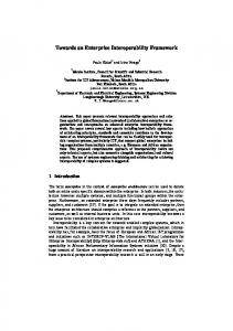
We will use this reference model to address model interoperability, where amongst other things meta-models and ontologies will be used to define model transformations and model mappings between the different views of an enterprise system. In literature [9, 10] different dimensions of system design are identified: − System abstraction: This dimension of system design reflects the abstraction in terms of implementation independency and is addressed by MDD. − Genericity: is an important design rational and has impact on the adaptability and reusability of the system components. − Viewpoint: System models represent a complex and strongly interrelated network of model entities. To address different issues and for complexity reduction different viewpoint on the model are used. This viewpoint may also be regarded for interoperability. − Composition: Systems are iteratively composed in a hierarchy from individual objects to the system in the enterprise context. On each of this aggregation layers the entities have to be interoperable − Time: The system itself is modified in status, configuration and design. − Model abstraction: Meta-models help to describe and analyse the used models These dimensions can be used to analyse software systems or help to structure the system modelling process and to catalyse design decisions. Each of these dimensions may support interoperability achievements or could represent a challenge of interoperability. Figure 2 graphically organises these integration dimensions around the four identified system aspects defined in the interoperability framework.
System abstraction
Genericity
CIM PIM Product-line, Framework, Pattern
PSM
Enterprise Viewpoint
Code
Business Viewpoint System Viewpoint Realisation Viewpoint
Viewpoints
e ic rv cts Se pe s A Pr As oce pe ss ct s
In fo As rma pe t i o ct n s
n- nal No tio ts nc pec u F s A
System, Product
M0
M1
M2
M3
Model abstraction State
Object Component
Evolution
Service (Virtual) Enterprise
Time
Composition
Fig. 2. Integration dimensions with respect to the four system aspects
We need to be aware of these integration dimensions when analysing how to achieve model interoperability. When looking at two or more different models we need to ask ourselves questions such as: Do the models describe the same or different set of concerns. Do the models describe a generic problem or specific problem? Who are the stakeholders, what is the intended use of the models, and how are the different models related through different viewpoints? How are the models composed, and what are the relationships to sub-models? Are we looking at a fairly static or a highly dynamic model of a certain aspect of the system? Are the models on the same abstraction level or different abstraction levels? These questions are important with respect to the model-driven development being applied. If we are not conscious of how the different models relate to each other we will not be able achieve model interoperability. 3.2 Reference Model for Technical Integration The reference model for technical integration has been developed from a serviceoriented point of view where a software system provides a set of services required by the businesses and users of the enterprise. Services implemented by software should provide functionality to support e.g. business transactions, business collaborations and business processes, and business tasks performed by users. The architecture of the enterprise applications and software systems can be described according to a 4-tier reference architecture where each tier provides different software services required by the enterprise. The software system itself is coupled to a service bus that provides the necessary communication infrastructure required to deploy a distributed system. Infrastructure services such as composition, mediation,
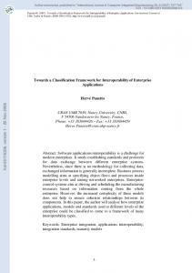
matchmaking and transformation that enables interoperability between software systems should be provided in such an environment. In addition we see that registries and repositories will play an important role in integrating software systems. We see the need for a model repository for managing models of various kinds, a service registry for managing naming, directory and location of services, an execution repository for managing information and state needed in the execution of software services and processes, and a data repository for managing results and traces of the executions. We use the service bus as an architectural pattern for handling technical integration of software systems. Figure 3 shows how a service bus comes into play when integrating two (or more) enterprises systems. The service bus will make use of infrastructure services, and registry and repository. Enterprise A (Physical World)
Enterprise B (Physical World)
Business Transactions Business Collaborations
Business Collaborations
Business Processes
Users
Business
Users
Business
Vertical Integration
Vertical Integration Model Mgmt.
Service Mgmt.
Exec. Mgmt.
Data Mgmt.
Software System
Infrastructure Services
User Services
Business Services
Resource Services
Service Bus
Service Bus
Service Bus
Resource Services
Business Services
Registry/Repository User Services
User Interface Services
Business Tasks
Business Processes
User Interface Services
Business Tasks
Business Transactions
Software System
Fig. 3. Reference model for technical integration
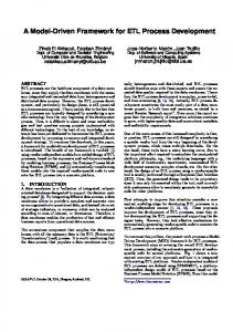
A software system can be structured according to a tiered architecture. We have defined a reference architecture that separates the architecture of a software system into four logical tiers. The reference architecture consists of a local user-space called the user service domain, and a shared transactional business-space called the business service domain. The four tiers are as follows: 1. User interface tier provides presentation and user dialog logic. Sometimes, it is useful to make the presentation and user dialog separation explicitly, in particular to support reuse of user dialog on multiple platforms with different graphical capabilities, e.g. Web, PDA and Mobile phones. 2. User service tier provides the user’s model, which may include user session logic and user-side representations of processes and information. It is an abstraction for
a set of business services, making the business service provision (and the communication mechanisms) transparent to the user interface tier. 3. Business service tier provides components that represent business functionality and pervasive functionality (vertical vs. horizontal services). This tier provides enterprise-level services, and is responsible for protecting the integrity of enterprise resources at the business logic level. Components in this tier can be processoriented, entity-oriented or workflow-oriented. For performance reasons, entityoriented components are typically not exposed outside of this tier. 4. Resource services tier provides global persistence services, typically in the form of databases. Resource adapters (e.g. JDBC or ODBC drivers) provide access, search and update services to databases and its data stored in a database management system (DBMS) like Oracle or Sybase.
Business Service Domain
User Service Domain
In addition to these four tiers we need a service communication bus so that services deployed at the various tiers can interoperate both within a tier and across tiers. User Interface Tier User Service Tier
LA
LS
Business Service Tier Resource Service Tier
RA
RA
Legend Service LA Local Adapter
LS
Local Storage
RA Resource Adapter
Database Inter-service communication
Service Bus (Middleware Services)
Fig. 4. 4-tier reference architecture for software system architectures
3.3 Reference Model for Applicative Integration The reference model for applicative integration has been developed based on work related to enterprise architecture frameworks and software architecture frameworks [11]. Here we look at how enterprise models and software models prescribed by enterprise modelling and software modelling approaches can be integrated into the overall framework. Enterprise and software models can be related in a holistic view, regardless of modelling language formalisms, by the use of meta-models. This is impor-
tant in order to understand the dependencies between the different models and views of a system, and will help us in achieving interoperability. The MDD methodology for software system development needs to follow a structured approach where interoperability requirements from business operations in a networked enterprise drive the development of software solutions. This means that MDD methodology for software systems needs to be related to enterprise architectures. A specific part of the methodology needs to address how the MDD concepts and the technical software components are reflected in a model world of the enterprise. Figure 5 shows how the model world, reflecting the applicative integration, is related to the reference model for conceptual integration and the reference model for technical integration. Enterprise and software models can be built to understand and analyse the physical world of an enterprise. An enterprise model describes a set of enterprise aspects, which amongst other things includes descriptions of the business operations that we refer to as business models. These business models provide a context for the software solutions that needs to be developed and integrated, and thus needs to be reflected in the software model. Software models describe how software systems are used to support the businesses of an enterprise. The software models further refines the business models in terms of software specification and software realisation models. The business model, the specification model and the realisation model for a software system should include descriptions of the four system aspects identified in the reference model for conceptual integration. The software models can be classified as CIM, PIM or PSM models according to a MDD abstraction. Enterprise System A
Enterprise Architecture A
Enterprise A
(MDD Abstraction)
(Model World)
(Physical World)
Computational Independent Model (CIM) MT
MT
Enterprise Model
Business Collaborations
Business Context
Vertical Integration
Architecture-Driven Modernisation (ADM)
Platform Specific Model (PSM)
Execution Platform A
Specification Models MT
Software Model
Realisation Models
Computational System A MT Model Transformation
Models of Service, Information Process and Non-Functional Aspects Models of other Enterprise Aspects
User Interface Services
Semantic Annotation
MT
Users
Business
MT
User Services
Model-Driven Architecture (MDA)
Platform Independent Model (PIM)
Business Tasks
Business Processes
Business Models Semantic Annotation
Business Transactions
MT
Business Services
MT
Model-Driven Architecture (MDA) & Architecture-Driven Modernisation (ADM)
Resource Services
Ontologies
Service Bus
Semantic Annotation
Software System
Fig. 5. Reference Model for Applicative Integration
The model world corresponds to the set of models prescribed by a MDD methodology. In our interoperability framework we have identified a set of models that we see
useful in achieving interoperability. However, we also acknowledge the fact that this is just a baseline. Different enterprises must be able to develop their own software views that they see purposeful in each business operation. It is important that the applicative integration supports the development of a set of shared views amongst different stakeholders and provides means for managing the dependencies between these views. In order to satisfy these criteria we believe a viewpoint-based integration approach must be chosen. This allows incorporating viewpoints, which are implicitly or explicitly defined by other enterprise or software modelling approaches into an applicative framework. The number of viewpoints to be used depends on the nature of the system and its stakeholders. In ATHENA [3] we will develop interoperability profiles that provide specific guidelines for how to apply model-driven development of software systems in four different business domains; Supply chain management where stable supply chains and dynamic supply networks will be considered. Collaborative product development in which cross-functional and cross-organisational teams collaborate in product development. e-Procurement focusing on electronic purchasing and selling of goods and services. Portfolio management focusing on project classifications, selection, prioritisation, and resource allocation. In each of these business domains we find domain-specific dictionaries, thesauri, nomenclatures and coding that will have impact on the development and usage of domain-specific reference ontologies. Furthermore, industry standards, and legislations and regulations given by the national legislative assemblies must also be taken into consideration. Each of these domains may prioritise specific software concerns and aspects differently and require their own custom-tailored views or models. We have identified three basic viewpoints that can be used as a starting point for viewpoint-based integration of software systems; Context viewpoint focusing on the business context of the software system, system viewpoint focusing on the specification of the main components of the software system, and realisation viewpoint focusing on the implementation of the software system. Figure 6 illustrates the viewpoint metaphor exemplified using the three basic viewpoints. A business analyst is concerned with aspects related to the business context of the software system within the networked enterprise. The business view includes e.g. business process models. A system architect is concerned with aspects related to the specification of the software system. The specification view includes e.g. service and interface models. A software developer is concerned with aspects related to the realisation of the software system. The realisation view includes e.g. interaction and data models
FOFAS bør kunne oppdatere ARCADE
Lower Echelon Unit
Joint Level
: COP
Establish/maintain frequency pool
Actual and planned ARCADE data
Receive ARCADE data
Receive COP Receive frequency requirements from lower level
draft TASKORG : Frequency requirements From Div 6, FO/I, KA mobile avd, LV
new campaign new operation Generate Verify Frequency list Frequency list
final TASKORG : Frequency requirements
list : Frequencies
temporary list : Frequencies
Verify security level new campaign new operation Distribute temporary Distribute Frequency list Frequency list verified list : Frequencies
temp verified list : Frequencies
Business View
ARCADE system COPdistributor
Business Analyst
e.g. Service & Interface Model Deployed Unit #1
Specification Viewpoint
Command Center InformationService #2
InformationServiceRadio #1
ProcessingService iProcess
Information
Information Satelite Ethernet
Deployed Unit #2 NotificationService iNotification iPublish
Specification View
e.g. Business Process Model
Business Viewpoint
System Architect
Realisation Viewpoint Legend Networked Enterprise
SOI
Software System
op2
Addressee
Telephone Directory
cryptoKeys
Decoding list
COP
Frequency requirements - emitterType - emiss oinType - area - class of station[mobil e, point-point, ground-air] - timerange - usage[send, receive,...] - securityLabel[(NATO) unclassifi ed, restricted, confidential, s ecret]
Main frequencies - emitterType - frequency - emissi onType - area(pol ygon, circl e) - class of station(mobile, poi nt-poi nt, ground-air)
Frequencies
Subnet - nettId - nettType - name - frequency - frequencyChangeTime - newFrequency - frequencyFMprai - frequencyDigPray - areaCode - KVTid - KVTchangeTime
Realisation View
op1
e.g. Interaction & Data Model
Software Developer
Fig. 6. Illustration of the three basic viewpoints and their corresponding views
4 Example – Inventory Min/Max replenishment scenario As a part of the work of defining the framework presented in this paper a student project was performed over a couple of months. The task for the students was to take an example integration scenario and create a set of models that were sufficient to be used for further transformations into new models and code. The goal was to be able to generate a running business process performing the integration scenario. The target platform for execution was BPEL running on IBMs BPWS4J2 server. In addition to creating models and code the students were to come up with observations of shortcomings in the different tools, methods and modelling languages. The experiences from this exercise were brought into the process of defining the framework presented in this paper. The scenario that was chosen was “Inventory Min/Max replenishment” as defined by the Automotive Industry Action Group (AIAG) [12], related to supply chain management. The idea behind this process is to let the supplier see the inventory level of the customer with minimum and maximum levels of inventory for a specific inventory item. Based on this information the supplier can perform inventory replenish2
BPWS4J, http://www.alphaworks.ibm.com/tech/bpws4j
ment so that the actual inventory level for an item is “automatically” kept between the minimum and maximum levels defined. The document defines the process and the information passed using the UN/CEFACT Unified Modeling Methodology [13]. At a high level one can say that there were three main models. Initially the partition into these three main model types was taken from [14], but indicated below, these are easily mapable to the aspects defined in this paper; 1. Activities, a model that defined the Min/Max process including actors, activities and information flow. This model describes the process aspects as defined in the interoperability framework. 2. Interactions, a model that defined the different computational services that would be part of the automated process and how they interact using defined interfaces. This model describes the service aspects as defined in the interoperability framework. 3. Information, a model that defined the information that was passed between the different activities and services in the process. This model describes the information aspects as defined in the interoperability framework. No models describing the non-functional aspects were created in this exercise. All of the models created can be viewed as platform independent models. One of the ideas behind the framework is that different languages or notations can be used to define the needed models. In order to discuss pros and cons of different methods and notations it was chosen to create 2 sets of models, one using the Business Process Modelling Notation (BPMN) [15] and one using the Business Process Definition Metamodel (BPDM) [16]. These would be used to generate the needed BPEL and WSDL descriptions using the UMT3 tool for code generation. BPMN models for the scenario were created using the Metis4 tool from Computas. BPDM has defined a UML 2.0 profile for definition of BPDM models. In this exercise the Enterprise Architect5 tool from Sparx Systems was chosen since just about was the only tool that had support for UML 2.0 at the point in time that this exercise was carried out. Due to limitations in the chosen tools it was hard to export the model information to a format that could be used by the UMT tool. It would be possible to implement, but this would mean spending resources on something that would not really add value to the exercise. To get around this problem it was chosen to create a UML 1.4 model based on the BPDM and the BPMN model using the ACE-GIS UML profile [17, 18]. From this model information UMT was able to generate BPEL and WSDL information that had to be manually crafted to be executed by the execution engine. The resulting web services (as executed by the execution engine) are business services as defined in the business service tier of 4-tier reference architecture described in section 3.2. The approach of modelling process, service and information aspects, as defined in the framework, does provide enough domain information in order to create platform specific models. 3
UML Model Transformation Tool, http://umt-qvt.sourceforge.net/ Metis, http://www.computas.com/metis 5 Enterprise Architect, http://www.sparxsystems.com.au/ea.htm 4
5 Related Work The IDEAS Interoperability Framework, developed in the IDEAS project [19], provides four different areas for structuring interoperability issues of enterprise applications; Business layer focusing on business environment and business processes. Knowledge layer focusing on organisational roles, skills and competencies of employees, and knowledge assets. ICT systems layer focusing on applications, data and communication components. Semantic dimension, cutting across the three identified layers, focusing on supporting mutual understanding on all layers. The ECMA/NIST (European Computer Manufacturers Association/National Institute of Standards and Technology) has developed a reference model for distributed system integration [20]. The ECMA/NIST approach separates integration into four different categories; Data Integration addressing the degree to which tools are able to share common data and information. Control Integration addressing the degree to which tools are able to interact directly with each other, by requesting and providing services. Process Integration addressing the degree to which the user’s working process and use of tools can be guided by a model of the work process and the methodology to be followed. Presentation Integration addressing the degree to which a userinterface program might provide access to the functionality needed by the user through a common look and feel. E-Commerce Integration Meta-Framework (ECIMF) defines recommended interoperability methodology, and the technical specification and base tools needed to prepare specific comparisons of concrete frameworks [21]. The proposed ECIMF methodology for analysis and modelling of the transformations between e-commerce frameworks follows a layered approach. In order to analyse the problem domain one has to split it into layers of abstraction, applying top-down technique to classify the entities and their mutual relationships. The Reference Model for Open Distributed Processing (RM-ODP) [22-25] is an ISO standard focusing on open distributed processing systems. RM-ODP divides the specification of ODP systems into five different, but related, viewpoints. The viewpoints in RM-ODP are: enterprise viewpoint (focuses on purpose, scope and policies), information viewpoint (focuses on information processing and relationships between information objects), computational viewpoint (focuses on functional specification and decomposition), engineering viewpoint (focuses on how to solve distribution issues), and technology viewpoint (focuses on specific technology and solutions). The interoperability framework presented in this paper addresses much of the same interoperability elements identified in the above framework and approaches, but relates them more closely to software models in a model-driven development environment.
6 Conclusions and future work We will conclude this paper by addressing each of the objectives or design rationales for the development of the interoperability framework. − The reference model for applicative integration clearly indicates that software solutions cannot be developed in isolation if the goal is to achieve interoperability between business units within and across virtual networked enterprises. The software development process and models must be related to the enterprise and business needs of an enterprise. We believe that a viewpoint-based integration approach provide a good foundation for relating different models and views in a holistic approach where software architectures and enterprise architectures can be related. − The reference model for technical integration provides a 4-tier reference architecture for describing software systems as a set of services addressing business and user needs. These software services are connected using a service bus that provides infrastructure, registry and repository services for integrating software. − The reference model for conceptual integration provides a basic understanding of MDD concepts that can be integrated into model-driven software development processes. − Finally, we believe that the reference models provided can be used to structure software technologies, frameworks and methodologies which can be found today. The reference models described will be used in the development of more structured methodologies focusing on different business domains as well as the development of infrastructure, registry and repository services to enable interoperability between software systems. In particular we will look into the specification of a set of UML 2.0 profiles for the four system aspects identified in the reference model for conceptual integration. This work is carried out in the context of ATHENA [3] and INTEROP [4]. ATHENA is an Integrated Project supported by the European Commission and INTEROP is a Network of Excellence supported by the European Commission. The main research challenge of both projects is to address interoperability for enterprise applications and software.
References 1. IEEE, "IEEE Standard Computer Dictionary: A Compilation of IEEE Standard Computer Glossaries," Institute of Electrical and Electronics Engineers, New York, NY 1990. 2. Object Management Group, "MDA Guide Version 1.0.1," Object Management Group omg/2003-06-01, 12th June 2003. 3. ATHENA, "ATHENA Public Web Site", http://www.athena-ip.org/, (accessed: 2004). 4. INTEROP, "INTEROP Portal", http://www.interop-noe.org/, (accessed: 2004). 5. IEEE, "IEEE Std 1471-2000: IEEE Recommended Practice for Architectural Description of Software-Intensive Systems," IEEE, October 2000.
6. Object Management Group, "OMG Unified Modeling Language Specification Version 1.5," Object Management Group, Specification formal/03-03-01, March 2003. 7. Object Management Group, "UML 2.0 Infrastructure Final Adopted Specification," Object Management Group, Specification ptc/03-09-15, 2003. 8. Object Management Group, "UML 2.0 Superstructure Final Adopted Specification," Object Management Group, Specification ptc/03-08-02, 2003. 9. C. Atkinson, J. Bayer, C. Bunse, E. Kamsties, O. Laitenberger, R. Laqua, D. Muthig, B. Paech, J. Wust, and J. Zettel, Component-based Product Line Engineering with UML: Addison-Wesley, 2002. 10. D. F. D'Souza and A. C. Wills, Object, Components, and Frameworks with UML - The Catalysis Approach: Addison Wesley Longman, Inc., 1998. 11. B. Elvesæter, T. Neple, J. Ø. Aagedal, R. K. Rolfsen, and O. Ø. Stensli, "MACCIS 2.0 - An Architecture Description Framework for Technical Infostructures and their Enterprise Environment," presented at Command and Control Research and Technology Symposium, San Diego, USA, 2004. 12. "Inventory Visiblilty and interoperability Min/Max Replenishment," Automotive Industry Action Group (AIAG) 2003. 13. UN/CEFACT, "UN/CEFACT Modelling Methodology (UMM) User Guide," UN/CEFACT CEFACT/TMG/N093, 2003. 14. "Infrastructure for electronic commerce - Application readable models in an open infrastructure," Norsk Edipro 2002. 15. "Business Process Modeling Notation (BPMN)," Business Process Management Initiative (BPMI) 2004. 16. "Updated Joint revised Business Process Definition Metamodel submission," Object Management Group bei/04-01-02, 2004. 17. D. Skogan, R. Grønmo, and I. Solheim, "Web Service Composition in UML," presented at The 8th International IEEE Enterprise Distributed Object Computing Conference (EDOC), Monterey, California, USA., 2004. 18. R. Grønmo, D. Skogan, I. Solheim, and J. Oldevik, "Model-Driven Web Service Development," International Journal of Web Services Research (JWSR), vol. 1, 2004. 19. IDEAS, "IDEAS Home Page", http://www.ideas-roadmap.net/, (accessed: 2004). 20. ECMA, "Reference Model for Frameworks of Software Engineering Environments, 3rd ed," ECMA, Technical Report NIST 500-211, ECMA TR/55, 1993. 21. ECIMF, "E-Commerce Integration Meta-Framework - General Methodology (ECIMFGM)," CEN/ISSS/WS-EC/ECIMF, Draft Version 0.3, 28.11 2001. 22. ITU-TS, "Basic Reference Model of Open Distributed Processing - Part 1: Overview and guide to use the Reference Model," Rec.X901 (ISO/IEC 10746-1), 1995. 23. ITU-TS, "Basic Reference Model of Open Distributed Processing - Part 2: Descriptive model," Rec.X902 (ISO/IEC 10746-2), 1995. 24. ITU-TS, "Basic Reference Model of Open Distributed Processing - Part 3: Prescriptive model," Rec.X903 (ISO/IEC 10746-3), 1995. 25. ITU-TS, "Basic Reference Model of Open Distributed Processing - Part 4: Architectural Semantics," Rec.X904 (ISO/IEC 10746-4), 1995.