dard edition (J2SE) 5.0, C# and XDoclet. J2SE. 5.0 implements attributes as annotations, and the. Enterprise Java Beans (EJB) 3.0 extensively uses them to ...
158 推薦論文● SPA2005
mTurnpike: a Model-driven Framework for Domain Specific Software Development Hiroshi Wada Junichi Suzuki Katsuya Oba Shingo Takada Norihisa Doi This paper describes and empirically evaluates a new model-driven framework, called Modeling Turnpike (or mTurnpike), which allows developers to effectively model and program domain concepts (ideas and mechanisms specific to a particular business or technology domain). By leveraging UML metamodeling and attribute-oriented programming, mTurnpike provides an abstraction to represent domain concepts at the modeling and programming layers simultaneously. The frontend system of mTurnpike transforms domain concepts between the modeling and programming layers. Its backend system combines domain models and programs, and transforms them to the final (compilable) source code. This paper focuses on the mTurnpike frontend system, and describes its design, implementation and performance implications.
1 Introduction Modeling technologies have matured to the point where they can offer significant leverage in all aspects of software development [1]. For example, the Unified Modeling Language (UML) provides a rich set of modeling notations and semantics, and allows developers to specify and communicate their application designs at a higher level of abstraction [2]. The notion of model-driven development (MDD) aims to build application design models and transform them into running applications. Given modern modeling technologies, the focus of software development has been shifting away from implementation technology domains toward the concepts and semantics in problem domains [3]. A key goal of modeling technologies is to map modドメイン特化型開発のためのモデル駆動フレームワーク. 和田 周, 鈴木 純一, マサチューセッツ大学ボストン校計算 機科学部, University of Massachusetts Boston. 大場 克哉, 株式会社オージス総研, OGIS-RI. 高田 眞吾, 慶應義塾大学理工学部, Keio University. 土居 範久, 中央大学理工学部, Chuo University. コンピュータソフトウェア, Vol.23, No.3 (2006), pp.158–169.
[論文] 2005 年 6 月 30 日受付. 本論文は,第 8 回プログラミングおよび応用のシステム に関するワークショップ (SPA 2005,ソフトウェアシ ステム研究会主催) 発表論文をもとに発展させたもので ある.
eling concepts more directly to domain concepts so that it becomes easier to specify applications [4]. In order to implement domain concepts with modeling technologies, traditional MDD tools allow developers to model domain concepts with modeling languages (e.g. UML), generate skeleton programs in general-purpose programming languages (e.g. Java) from the domain models, and complete the generated skeleton programs by, for example, adding method code. Since general-purpose programming languages can not directly express domain concepts, programmers often suffer from abstraction gap between domain concepts and generated skeleton programs. For example, the granularity of skeleton programs is usually much finer than that of domain concepts. They also tend to be complicated, sometimes even chaotic, to read and maintain. Thus, it is hard for programmers to obtain broader views of application designs, and they have to repeatedly go up and down abstraction gap to identify where to implement what in skeleton programs. As a result, in traditional MDD tools, programmers do not enjoy the benefits of modeling domain concepts at a higher level of abstraction. This paper addresses the above issue and proposes a development framework, called Modeling Turnpike (or mTurnpike), which supports a new model-driven strategy to implement domain concepts. mTurnpike allows developers to model and
Vol. 23 No. 3 July 2006 program domain concepts at the equal level of abstraction and to transform them to the final (compilable) source code in a seamless manner. Leveraging UML metamodeling and attribute-oriented programming, mTurnpike provides an abstraction to represent domain concepts at the modeling and programming layers simultaneously. At the modeling layer, domain concepts are represented as a Domain Specific Model (DSM), which is a set of UML diagrams. In mTurnpike, UML diagrams are expressed with a UML profile; a UML metamodel that extends the UML standard metamodel [2]. At the programming layer, domain concepts are represented as a Domain Specific Code (DSC), which consists of attribute-oriented programs. Attributes are declarative marks, associated with program elements (e.g. classes and interfaces), to indicate that the program elements maintain application-specific or domain-specific semantics [6] [7]. The frontend system of mTurnpike transforms domain concepts from the modeling layer to programming layer, and vice versa, by providing a seamless mapping between DSMs and DSCs. The backend system of mTurnpike transforms a DSM and DSC into a more detailed model and program by applying a given transformation rule. mTurnpike allows developers to define arbitrary transformation rules, each of which specifies how to specialize a DSM and DSC to particular implementation and/or deployment technologies. For example, a transformation rule may specialize them to a database system, while another rule may specialize them to a remoting system. mTurnpike combines the specialized DSM and DSC to generate the final (compilable) source code. This paper focuses on the frontend system of mTurnpike, and describes its design, implementation and performance implications.
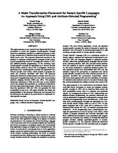
2 A Motivating Example This section illustrates an example of the issue described in Section 1 (i.e. an issue of abstraction gap in MDD tools) to motivate mTurnpike. Fig.1 shows a UML model (DSM) that represents a service-oriented distributed system with domain concepts such as service, connection between services and message†1 . Given the domain concepts, traditional MDD tools generate a skeleton program
159
Client
invocationSemantics = Async
OrderForm
Server RevisedOrderForm
OrderConn OrderLogger OrderFormTransformer
Domain concepts Skeleton program
Fig. 1
Transformer
Filter
Logger
Client
Service onMessage()
Server
OrderForm
Message
RevisedOrderForm
Dispatcher
Receiver
AsyncDispacher
AsyncReceiver
Domain Concepts at the Modeling and Programming Layers
in a general-purpose programming language. For example, the skeleton program may contain the program elements shown at the bottom of Fig. 1. As shown in Fig.1, there are not always clear oneto-one relationship between domain concepts and generated program elements, and the granularity of the program elements is finer than that of domain concepts. For example, Connector disappears at the programming layer. Service is implemented with two classes. Several implementation-specific classes (e.g. Dispacher and Receiver) appear at the programming layer, although they are not in the modeling layer. As described in Section 1, this abstraction gap has a negative impact on the productivity of programmers. It can cancel the productivity gain through application design with domain concepts at the modeling layer. Rather than general-purpose programming languages, mTurnpike uses attribute-oriented programs to directly represent domain concepts at the programming layer. It allows modelers†2 and programmers to deal with the same set of domain concepts in different representations (i.e. UML models and attribute-oriented programs), yet at the same level of abstraction.
†1 This model is designed with a UML profile for service oriented architecture. See Section 6 and [13] [14] for more details on this profile. †2 This paper assumes modelers are familiar with particular domains but not programming experts.
160
コンピュータソフトウェア
3 Attribute-Oriented Programming Attribute-oriented programming is a programlevel marking technique. Programmers can mark program elements to indicate that they maintain application-specific or domain-specific semantics [6] [7]. For example, a programmer may define a logging attribute and associate it with a method to indicate the method implements a logging function, while another may define a web service attribute and associate it with a class to indicate the class is implemented as a web service. Attributes separate application’s core logic from applicationspecific or domain-specific semantics (e.g. logging and web service functions). By hiding the implementation details of those semantics from programs, attributes increase the level of programming abstraction and reduce programming complexity, resulting in simpler and more readable programs. The program elements associated with attributes are transformed to more detailed programs by a supporting tool (e.g. pre-processor). For example, a pre-processor may insert a logging program into the methods associated with a logging attribute. Attribute-oriented programming is well accepted in several languages and tools such as Java 2 standard edition (J2SE) 5.0, C# and XDoclet. J2SE 5.0 implements attributes as annotations, and the Enterprise Java Beans (EJB) 3.0 extensively uses them to make EJB programming simpler [8]. Here is an example using an EJB annotation. @entity class Customer{...}
The @entity annotation is associated with the class Customer. It instructs Customer to be implemented as an entity bean. A pre-processor in EJB, called annotation processor, takes this annotated code and applies a certain transformation rule to generate the interfaces and classes required to implement Customer as an entity bean (i.e. remote interface, home interface and implementation class). The EJB annotation processor follows the transformation rules defined in the EJB specification. In addition to predefined annotations, J2SE 5.0 allows developers to define their own (user-defined) annotations. There are two types of user-defined annotations: marker annotations and member annotations. Here is an example marker annotation. public @interface Async{ }
A marker annotation is defined with the keyword @interface. public class Server{ @Async public boolean orderItem(...){...} }
In this example, the Async annotation is associated with orderItem(), indicating it is an asynchronous method. Then, a developer defines a transformation rule for the annotation, and creates a user-defined annotation processor that implements the transformation rule. The annotation processor may replace each annotated method with a method implementing asynchronous invocations. A member annotation, the second type of userdefined annotations, contains member variables. public @interface Service{ String url(); int timeOut(); }
In this example, the Service annotation has the url and timeOut member variables. @Service( url = "soap://host/orderentry/", timeOut = 600 ) public class Server{...}
Here, the Service annotation is associated with the class Server, instructing Server to be deployed as a remotelly accessible service. url defines where to deploy Server and the protocol to access Server. timeOut specifies time out period for method invocations. An annotation processor for the Service annotation takes an annotated class and generates additional classes and/or methods required to implement a SOAP-accessible web service.
4 Modeling Turnpike mTurnpike consists of the frontend and backend systems (Fig. 2). The frontend system is implemented as DSC Generator, and the backend system is implemented as DSL Transformer. Every component in mTurnpike is implemented with Java. The frontend system transforms domain concepts from the modeling layer to programming layer, and vice versa, by providing a seamless mapping between DSMs and DSCs. In mTurnpike, a set of domain concepts is defined as a UML profile, which is a metamodel extending the UML standard metamodel. The UML extension mechanism provides several model elements, such as stereotype and tagged-value, in order to add application-specific or domain-specific modeling semantics to the UML standard metamodel [9]. Stereotypes are specified
Vol. 23 No. 3 July 2006
161
Server {url=“http://host/orderentry/”, timeout = 600}
Application Developers
Abstraction Modelers Programmers Write method code level Describe models no DSM DSC it re cra l DSC hg ts ev Generator i be HAL DSL Transformer DSM Transformer
no ti re catr w oL sbA
le ve L
Transformation rules
Plain UML Models
Visual Models Fig. 2
DSC Transformer
Skeleton Code Generator
+ orderItem(OrderForm) : boolean
dn et no rF dn ek ca B
Final (Compilable) Code
Representation
Textual Code
mTurnpike Architecture
as metaclasses extending UML’s standard metaclasses, and tagged-values are specified as properties of stereotypes (i.e. extended metaclasses). Given domain concepts, a DSM is represented as a set of UML class and composite structure diagrams. Each DSC consists of Java interfaces and classes decorated with the J2SE 5.0 annotations. The annotated code follows the J2SE 5.0 syntax to define marker and member annotations. The backend system of mTurnpike transforms a DSM and DSC into a more detailed model and program that specialize in particular implementation and/or deployment technologies. Then, it combines the specialized DSM and DSC to generate the final (compilable) code (Fig. 2). In mTurnpike, the frontend and backend systems are separated by design. mTurnpike clearly separates the task to model and program domain models from the task to transform them into the final code. This design strategy improves separation of concerns between modelers/programmers and platform engineers†3 . Modelers and programmers do not have to know how domain concepts are implemented and deployed in detail. Platform engineers †3 Platform engineers possess expertise in platform technologies on which DSMs and DSCs are deployed. They are responsible for defining transformation rules applied to DSMs and DSCs.
Fig. 3
UML Class Server (DSM)
do not have to know the details of domain concepts. As a result, mTurnpike can reduce the complexity in application development. This design strategy also allows DSMs/DSCs and transformation rules to evolve independently. Since DSMs and DSCs do not depend on transformation rules, mTurnpike can specialize a single set of DSM and DSC to different implementation and deployment technologies by using different transformation rules. When it comes time to change a running application, modelers/programmers make the changes in the application’s DSM and DSC and leave transformation rules alone. When retargeting an application to a different implementation and/or deployment technology (e.g. Java RMI to Java Messaging Service (JMS)), platform engineers define (or choose) a transformation rule for the new target technology and regenerate the final code. As such, mTurnpike can make domain concepts (i.e. DSMs and DSCs) reusable and extend their longevity. 4. 1 Mapping between DSMs and DSCs mTurnpike implements the mapping rules shown in Table 1 to transform DSMs to DSCs, and vice versa. Figure 3 depicts an example DSM, the UML class Server stereotyped as with a tagged-value. mTurnpike transforms the UML class to the following Java code. • Java class Server (DSC) @Service(url = "http://host/orderentry/", timeout = 600) public class Server{ public boolean orderItem(OrderForm order){}}
• Member annotation entitybean (DSC) @interface Service{ String url(); long timeout(); }
4. 2 mTurnpike Frontend System The mTurnpike frontend system is implemented by DSC Generator (Fig. 2). It performs transformations between DSMs and DSCs based on the mapping rules shown in Table 1. The following five
162
コンピュータソフトウェア Table 1
Mapping rules between DSMs and DSCs
UML Elements in DSM
Java Elements in DSC
Definition of a stereotype that has no tagged-values
Definition of a marker annotation
Definition of a stereotype that has tagged-values
Definition of a member annotation
Definition of a tagged-value
Definition of a member variable in a member annotation
Package
Package
Class and interface
Class and interface
Method and data field
Method and data field
Modifier and visibility
Modifier and visibility
Primitive type
Primitive type
Stereotype that has no tagged-values
Marker annotation
Stereotype that has tagged-values
Member annotation
Tagged-value
Member annotation’s member variable
steps involve in the transformation. (1) Loading a DSM to build a UML tree: DSC Generator imports a DSM as a representation of the XML Metadata Interchange (XMI) 2.0 [10]. Developers can generate XMI descriptions of their DSMs using any UML tools that support XMI 2.0. Here is an example XMI description showing the class Server in Fig. 3. ... ...
The tag defines a class, and its child element appliedStereotypeInstance references a stereotype. In this example, the stereotype is referenced with its identifier st. The tag defines a tagged-value.
For loading XMI descriptions and building UML trees, DSC Generator uses the Eclipse Modeling Framework (EMF)†4 and Eclipse-UML2†5 . A UML tree is an in-memory data structure that represents UML model information. Once a UML tree is constructed, DSC Generator validates the UML tree (i.e. an input DSM) against the standard UML metamodel. It examines if the input DSM follows the syntax and semantics defined in the standard UML metamodel. DSC Generator also validates the input DSM against a UML profile. For example, it checks if the DSM uses appropriate stereotypes and tagged-values defined in the UML profile. (2) Building a JAST for Domain Concepts: Once a UML tree is built and validated, DSC Generator constructs a Java Abstract Syntax Tree (JAST) to represent domain concepts (i.e. UML profile) that an input DSM follows. Based on the mapping rules shown in Table 1, this process traverses a UML tree to convert the definitions of stereotypes and tagged-values in the UML tree into the definitions of annotations in a JAST. Fig. 4 shows some key data structures to con†4 http://www.eclipse.org/emf/ †5 http://www.eclipse.org/uml2/. Eclipse-UML2 implements the UML standard metamodel as a set of Java objects on EMF. mTunpike chose Eclipse-UML2 because it was the only publiclyavailable implementation of the UML 2.0 metamodel when the authors started implementing mTurnpike. The conformance with UML 2.0 is important because of its improved and unambiguous mechanism to extend the UML metamodel.
Vol. 23 No. 3 July 2006
163
>
>
AnnotationMemberType
AnnotatableElement
+ type
Package Parameter * *
AnnotationMemberDefinition
+ meta
+ type
Type AnnotationDefinition
Field + type
+ meta
Classifier
Feature
+
* + parameter
return
Operation
* + annotations * AnnotationMember
* Class
implements *
Interface
Annotation
-value:Object
Fig. 4
DataType
Enum
PrimitiveType
+ parent
+ parent
Key data structures to construct Java Abstract Syntax Trees
struct JASTs. Annotation represents an annotation. In order to represent a member annotation, Annotation has an association with AnnotationMembers, each of which represents a member variable. AnnotationMember keeps a value of member variable. AnnotationDefinition and AnnotationMemberDefinition represent the definitions of an annotation and an annotation’s member variable. They are powertypes of Annotation and AnnotationMember, respectively. (3) Building a JAST for a DSC: After constructing a JAST to represent a set of domain concepts (i.e. stereotypes and tagged-values), DSC Generator completes the JAST by converting the model elements in an input DSM (i.e. class and composite structure diagrams) into Java program elements. This process is also performed based on the mapping rules shown in Table 1. For example, a stereotyped UML class in a UML tree is converted to an annotated Java class in a JAST. DSC Generator builds a JAST using the JAST data structures shown in Fig. 4. In Fig. 4, AnnotatableElement is the root interface for the Java program elements that can be decorated by annotations. The following code fragment shows how DSC Generator transforms a stereotyped UML class to an annotated Java class. The method convertClass() takes a UML class and instantiates the class Class in a JAST, which represents a Java class (see Fig. 4). Then, the method transforms the stereotypes applied to the UML class to Java annotations by instantiating the class Annotation in resolveStereotypes(). import edu.umb.cs.dssg.mturnpike.java.ast.*;
Class convertClass( uml2.Class c_ ) { // create a Java class as a JAST node jast.Class c = new jast.Class(); // create a Java annotation(s), // if a UML class is stereotyped. resolveStereotypes( c, c_ ); return c; } void resolveStereotypes( jast.AnnotatableElement annotatable, uml2.Element element ) { // convert all stereotypes into // Java annotations. foreach( uml2.Stereotype s in element.getAppliedStereotypes() ){ // add an annotation to a Java element. jast.Annotation a = ... annotatable.addAnnotation( a ); } }
(4) Generating a DSC (annotation definitions): Once a JAST is constructed, DSC Generator generates annotation definitions in Java. Each JAST node has the toString() method, which generates Java source code corresponding to the JAST node. DSC Generator traverses a JAST and calls the method on instances of AnnotationDefinition and AnnotationMemberDefinition (Fig. 4). (5) Generating a DSC: Once generating annotation definitions, DSC Generator completes to generate a DSC (i.e. annotated code in Java). It traverses a JAST and calls the toString() method on each node in the JAST. After DSC Generator generates a DSC, programmers write method code in the generated DSC in order to implement dynamic behaviors for domain concepts. Please note that the methods in the generated DSC are empty because DSMs specify only the static structure of domain concepts (with UML class diagrams and composite structure diagrams). In addition to transformations from DSMs to DSCs, mTurnpike can perform reverse transforma-
164
コンピュータソフトウェア
tions from DSCs to DSMs. In a reverse transformation, mTurnpike parses a DSC with a lexical analyzer†6 , and builds a JAST with the data structure shown in Fig.4. The JAST is transformed to a UML tree and an XMI file using Eclipse-UML2 4. 3 mTurnpike Backend System The mTurnpike backend system consists of three components: DSM Transformer, Skeleton Code Generator and DSC Transformer (Fig. 2). DSM Transformer: DSM Transformer accepts a DSM as a UML tree built by DSC Generator, and specializes it to particular implementation and/or deployment technologies (Fig. 2). Given a transformation rule that a platform engineer defines, DSM Transformer transforms DSM model elements associated with stereotypes and tagged-values into plain UML model elements that have no stereotypes and tagged-values. For example, if a transformation specializes a DSM to Java RMI, the classes stereotyped as are converted to the classes implementing the java.rmi.Remote interface. DSM Transformer is implemented with the Model Transformation Framework (MTF)†7 , which is implemented on EMF and Eclipse-UML2. MTF provides a language to define transformation rules between EMF-based models. Each transformation rule consists of conditions and instructions. DSM Transformer traverses a DSM (i.e. a UML tree), identifies the DSM model elements that meet transformation conditions, and applies transformation instructions to them. This transformation process generates another UML tree that represents a model specializing in particular implementation and/or deployment technology. The following is an example transformation rule.
uml:Implementation i, uml:Interface c){ check interfaces(g.contract, c) } relate interfaces( uml:Interface c1, uml:Interface c2) when equals(c1.name, c2.name)
The keyword relate is used to define a transformation rule. This example defines four rules. Each rule accepts model elements as parameters and instructs how to transform them. For example, the first rule (class2class) accepts the classes stereotyped with , and transforms each of them to extend the interface Remote. Skeleton Code Generator: Skeleton Code Generator takes a UML tree created by DSM Transformer, and generates skeleton source code in Java (Fig. 2). It traverses an input UML tree, builds a JAST corresponding to the UML tree using the data structures shown in Fig. 4, and generates Java code from the JAST. Since the mTurnpike frontend system only supports structural UML diagrams, the methods in the generated code are empty. DSC Transformer: DSC Transformer accepts a DSC generated by DSC Generator, method code written on the DSC by programmers, and skeleton code generated by Skeleton Code Generator. Then, DSC Transformer combines them to generate the final compilable code. DSC Transformer extracts method code embedded in an input DSC, and copies the method code to an input skeleton code. DSC Transformer analyses a transformation rule to determine where to copy each method code in an input skeleton code. Fig. 5 depicts an example of this process. It shows how the orderItem() @Service ( url = "http://host/orderentry/", timeout = 600 ) public class Server{ booelan orderItem ( OrderForm orderform ){
OrderFormView.print( order.getId(), order.getName() ); ed … co }} odh te javax.ejb. javax.ejb. javax.ejb. EJB m SessionBean EJBObject EJBHome se ip oc ServerBean Server ServerHome re + orderItem( + orderItem( m ro OrderForm ) OrderForm ) fs na rT Javax.jms. JMS javax.jms. Message MessageListener SC D Order
relate class2class( uml:Class src when equals( match over src.stereotypes.name, "Service"), uml:Class tgt, uml:Interface tgt2 when equals( tgt2.name, "Remote") ) when equals(src.name, tgt.name){ implementation(tgt, tgt2) } relate implementation( uml:Class c1, uml:Interface c2){ realize(over c1.implementation, c2) } relate realize( †6 mTurnpike ’ s lexical analyzer is implemented with JavaCC (http://javacc.dev.java.net/). †7 www.alphaworks.ibm.com/tech/mtf
DSC
Server + orderItem( OrderForm )
Fig. 5
Method Extraction in DSC Transformer
Vol. 23 No. 3 July 2006 method in a DSC is extracted when specializing the DSC to EJB and JMS.
165
no operation and no field
25
15
5 operations and 5 fields 20
10 operations and 10 fields
5 Empirical Evaluation
10
30 operations and 30 fields 15
This section empirically evaluates the efficiency and memory footprint of the mTurnpike frontend system. 5. 1 Evaluation Results In order to evaluate the efficiency of the mTurnpike frontend system, Fig.6(a) and Fig.6(b) show the overhead to transform a DSM to a DSC, and a DSC to a DSM, respectively. Measurements use a Sun J2SE 5.0.4 VM running on a Windows 2000 PC with an AMD Sempron 3.0 Ghz CPU and 512MB memory. Each figure consists of 20 clusters, each of which shows the transformation overhead using the same number of classes, operations and data fields. For example, the nearest cluster shows the overhead to transform a DSM that contains 10 classes, each of which has no operations and data fields. The furthermost cluster shows the overhead to transform a DSM that contains 500 classes, each of which has 30 operations and 30 data fields. Each cluster consists of four bars. The leftmost bar shows the transformation overhead in a configuration where each DSM class has no stereotypes and tagged-values. The second bar from the left shows the overhead in the case that each DSM class has a stereotype and a tagged-value. In the third bar from the left, each DSM class has two stereotypes and five taggedvalues. In the rightmost bar, each DSM class has five stereotypes and 10 tagged-values. Figs. 6(a) and 6(b) illustrate that the transformation overhead is small enough and acceptable (below 5 seconds) in small-scale to mid-scale application development, where each of 300 classes has 10 operations, 10 data fields, 2 stereotypes and 5 tagged-values. mTurnpike does not interrupt developers’ modeling and programming work severely. Figs. 7 and 8 depict the time to execute each of the functional steps to transform a DSM to a DSC, and a DSC to a DSM, respectively (see Section 4. 2). In the measurements, each class is configured to have five operations and five data fields. Fig. 7 shows that the most time-consuming step in a DSM to DSC transformation is building a JAST for a DSC. In this step, mTurnpike
10
5
5
0
0
100
50
10
500 300 # of classes
10
# of classes
Overhead of a transformation
Generating a DSC (classes) Generating a DSC (annotation definitions) Building a JAST for DSC (others) Building a JAST for DSC (fields) Building a JAST for DSC (operations) Building a JAST for DSC (annotations) Building a JAST for DSL (annotations definitions) Loading a DSM to build a UML tree
0.8
)s ( e im t
0.6
0 .0 4
0 .0 2
0.0 2
0 .33
0 .04
0.4
0.0 2
0 .07
0 .0 4
0.0 3
0.2
500
300
100
(b) DSC to DSM
(a) DSM to DSC Fig. 6
50
0 .1 6
0 .13 0 .17
0 .0 8
0 .0 9 0.2 0 0.1 1
0 .1 1
0 .1 1
0 .2 1
0 .21
0 .22
0 .1 2
0.0 50
Fig. 7
# of clas s es
1 00
Overhead breakdown in a DSM-DSC transformation
Generating a DSM (XMI) for profiled classes Applying a profile to classes Generating a DSM (XMI) for annotation definitions (profile) Building a UML tree for annotation definitions (profile) Generating a DSM (XMI) for classes Building a UML tree for classes Loading a DSC to build a JAST for classes Loading a DSC to build a JAST for annotation definitions 0.8
0.13
0.6
0.4
s) (m e im t
0.2
0.33
0.13
0 .07 0.1 3 0.16 0.06 0.0 6
0.06
0.1 8 0.18 0.14
0.1 4
0.14
0 .07
0.0 50
Fig. 8
1 00
# of clas s es
Overhead breakdown in a DSC-DSM transformation
calls the Java instanceof operator many times to check consistency between annotation definitions (instances of AnnotationDefinition and AnnotationMemberDefinition) and annotations (instances of Annotation and AnnotationMember) (see Fig.4). It is expensive to call instanceof. The
)s ( e im t
166
コンピュータソフトウェア
60
no operation and no field
70
5 operations and 5 fields 50
10 operations and 10 fields 30 operations and 30 fields
60 50
40
40 30
30 20
20
10
10 0
0
50
10
100
300
500 # of classes
(a) DSM to DSC Fig. 9
10
50
100
300
500 # of classes
(b) DSC to DSM
) B M ( no tia izil tu ryo m e m
UML2Switch switch( Element ) caseClass( Class ) caseOp( Operation ) Fig. 10
Visitor visit( Element ) visit( Class ) visit( Operation ) Fig. 11
more classes and stereotypes a DSM has, the more heavyweight it is to build a JAST for the DSC. Fig. 8 shows that the most time-consuming step in a DSC to DSM transformation is applying a UML profile to DSM classes. In this step, mTurnpike executes nested loops to decide which stereotype is applied to which class. The more classes and stereotypes a DSM has, the more heavyweight this decision making process is. In order to examine the memory footprint of the mTurnpike frontend system, Figs. 9(a) and 9(b) shows how much memory mTurnpike consumes to transform a DSM to a DSC, and a DSC to a DSM, respectively. mTurnpike consumes no more than 15MB to handle DSMs and DSCs produced in small-scale up to mid-scale projects, where each of 300 classes has 10 operations, 10 data fields, two stereotypes and five tagged-values. Since the memory footprint of mTurnpike is fairly small, developers do not need to upgrade their development environments (e.g. memory modules in their PCs). 5. 2 Performance Improvement The measurement result in Fig. 6(a) is obtained after a performance improvement work. This work reduces the overhead to traverse a UML tree and build a corresponding JAST by 4.8% up to 56.0% (20.3% in average). Eclipse-UML2 provides a standard API, called UML2Switch, to traverse a UML tree (Fig. 10). UML2Switch.switch() takes a UML element, determines its type and calls a method corresponding to the type. For example, when UML2Switch determines the type of a UML element is Class, it calls caseClass() to transform a UML class to a Java
Class
Operation
Tree Traversal with UML2Switch
Inject accept methods
Memory footprint in a transformation
Element
VisitorAspect Element accept( Visitor)
Class accept( Visitor)
Operation accept( Visitor)
UML2 Tree Traversal with Visitor
class. UML2Switch.switch() excessively calls the Java instanceof operator to perform type checking, and suffers from performance degradation. In order to improve overhead performance by avoiding excessive calls of instanceof, mTurnpike implements the visitor design pattern [25] as an alternative way to traverse a UML tree. The visitor pattern is designed to iterate tree nodes and call type-specific methods on a visitor object. Thus, developers do not need to explicitly determine the type of each node. This way, mTurnpike can reduce the number of instanceof invocations. The visitor pattern requires adding very similar method code to every node in a tree. The method (accept()) takes a visitor object and calls a type-specific method on the visitor depending on the type of each node (see Fig. 11). For example, Class.accept() calls Visitor.visit(Class). This means the accept() methods scatter over tree nodes. Therefore, mTurnpike encapsulates all the accept() methods in a single aspect [24], and injects them to tree nodes with AspectJ†8 . Thanks to the use of an aspect, it is not necessary to modify Eclipse-UML2 manually. Also, Eclipse-UML2 and visitor code can be updated separately.
6 Applications In order to demonstrate how to exploit mTurnpike in application development, it has been used to develop distributed systems with a UML profile for Service-Oriented Architecture (SOA) [13] [14]†9 . Fig. 1 shows an example UML model developed †8 http://eclipse.org/aspectj/
Vol. 23 No. 3 July 2006 with this profile. SOA is a distributed systems architecture that models a distributed system as a collection of services and interoperates them in a platform independent manner. The UML profile abstracts distributed systems using three major domain concepts, service interface, connections between services and message interface. It allows modelers to specify, as DSMs, connection semantics (e.g. queuing and secure connections), invocation semantics (e.g. synchronous and asynchronous invocations) and message filtering semantics (e.g. message conversion and aggregation). It is planned to support an Enterprise Service Bus†10 as an additional deployment platform.
7 Related Work mTurnpike has some functional commonality with existing MDD tools such as OptimalJ†11 , Rose XDE†12 , Together†13 , UMLX [11], KMF [12] and J3 [19]. They usually have two functional components: Model Transformer and Code Generator (Fig. 12). Similar to DSM Transformer in mTurnpike, Model Transformer accepts UML models that modelers describe with UML profiles, and converts them to more detailed models in accordance with transformation rules. Similar to Skeleton Code Generator in mTurnpike, Code Generator takes the UML models created by Model Transformer, and generates skeleton source code. A major difference between existing MDD tools and mTurnpike is the level of abstraction where programmers work. In existing MDD tools, programmers and modelers work at different abstraction levels (Fig. 12). Although modelers work on UML modeling at a higher abstraction level, programmers need to handle generated skeleton code at a lower abstraction level. It tends to be complicated, time consuming and error-prone to read and modify the skeleton source code. Unlike existing MDD tools, mTurnpike offers a new method to represent domain concepts at the †9 This work is one of the first attempts to exploit UML 2.0 to define and use a UML profile. †10 http://mule.codehaus.org/ †11 www.compuware.com/products/optimalj/ †12 www.ibm.com/software/ awdtools/developer/rosexde/ †13 www.borland.com/together/architect/
167
Describe Abstraction level models no Modelers ti re car l t Platform Engineers hg s ve Platform Independent i be Model HA L Define rules
Model Transformer no ti re car t w oL sbA
le ve L
Programmers
Transformation rules Code Generator
Platform Specific Model
Visual Models
Fig. 12
Write method code
Final (Compilable) Code
Representation
Textual Code
Traditional MDD process
programming layer through the notion of attributeoriented programming (Fig.2). Programmers implement method code in DSCs, before DSL Transformer specializes DSCs to particular implementation and/or deployment technologies. This means that programmers can focus on coding application’s core logic without handling the details on implementation and deployment technologies. Also, DSCs are much more readable and easier to maintain than the source code generated by Code Generators in existing MDD tools. Therefore, mTurnpike provides a higher productivity of programmers in implementing their applications. mTurnpike customizes existing languages (UML and Java) to specifically represent domain concepts. In that sense, this work parallels the research efforts to investigate domain specific languages (DSLs). A DSL is a programming or specification language that directly captures the concepts and semantics specific to a particular problem domain [5]. In mTurnpike, UML profiles and annotations are viewed as DSLs. mTurnpike employs a language-in-language (or piggyback) strategy to design DSLs. This strategy reuses the elements of an existing language as a hosting base for new DSLs [20] [21]. It is often used when the base language is well known, and it can lower the barrier to learn and access extended/customized DSLs. It is not always cost effective to define DSLs from scratch [17] [18]. DSLs can be visual or textual. GME [21], UDM
168
コンピュータソフトウェア
[22] and MetaEdit+†14 support visual DSLs to specify both structural and behavioral aspects of domain concepts. Visual DSLs help developers grasp broader views of their applications in an intuitive manner. [28] and [29] supports textual DSLs to specify both structural and behavioral aspects of domain concepts. Textual DSLs help developers easily define and control details in domain concepts (e.g. detailed behavioral specifications). mTurnpike supports both visual and textual DSLs. Visual DSLs (i.e. UML profiles) are used to specify the structural aspect of domain concepts, and textual DSLs (i.e. annotations) are used to define the behavioral aspects of domain concepts. This way, mTurnpike tries to maximize separation of concerns in modeling and programming domain concepts. There are few generic frameworks that support both visual and textual to define arbitrary domain concepts. The model-driven program transformation (MDPT) scheme transforms the source code written in general purpose programming languages into a visual DSL(s) and keeps the consistency between source code and DSLs [26] [27]. Although this scheme supports visual DSLs and textual code, developers are not allowed to write or modify source code. They have to specify structural and behavioral aspects only with visual DSLs. In mTurnpike, different types of developers use different types of DSLs; modelers use visual DSLs to define structural aspect, and programmers use textual DSLs to define behavioral aspect. Similar to mTurnpike, executable UML (xUML) allows developers to specify application’s structure with UML models (class and statechart diagrams) and application’s behaviors with action languages (textual languages) [23]. However, xUML does not have a mechanism to specifically express domain concepts. It does not support metamodel customization (or UML profiling).
8 Concluding Remarks This paper describes and empirically evaluates a new model-driven development framework called mTurnpike. In addition to an overview of architectural design, this paper focuses on the frontend system of mTurnpike and describes its design, im†14 www.metacase.com
plementation and performance implications. Empirical measurement results show that mTurnpike works efficiently with a small memory footprint in small-scale to mid-scale application development. Several extensions to mTurnpike are planned as future work. mTurnpike currently supports only one UML profile for each transformation from a DSM to compilable code. It will be extended to generate compilable code through combining DSMs and DSCs written in multiple UML profiles. Future experiments will evaluate how it impacts on the design and performance of mTurnpike to use multiple DSLs simultaneously. Two other UML profiles are being designed on mTurnpike. The first one is a UML profile to specify the resources, procedures and policies in insurance claims processing in the workers compensation domain. The authors of the paper are working with industry experts to develop this profile. The second one is a UML profile to design portal web sites using the Java Portlet and Web Services for Remote Portlets specifications [15] [16]. It allows users to specify common functionalities in portal site design, such as login, database access, content aggregation, user profile management and user interface personalization. It is planned to enhance an existing ecological observations portal†15 with this profile.
Acknowledgement The authors would like to thank Michael Moore and Adam Malinowski for their valuable comments that improved the quality of the paper. This work is supported in part by OGIS International, Inc. and Electric Power Development Co., Ltd. References [ 1 ] Selic, B.,: The Pragmatics of Model-Driven Development, IEEE Software, Vol. 20, No. 5(2003), pp. 19–25. [ 2 ] Object Management Group: UML 2.0 Superstructure Specification, 2004. [ 3 ] Gray, J., Rossi, M., Tolvanen, J., (eds.): DomainSpecific Modeling with Visual Languages, Special issue of Journal of Visual Languages and Computing, Vol. 15, Issues 3–4, Elsevier, 2004. [ 4 ] Booch, G., Brown, A., Iyengar, S., Rumbaugh, J. and Selic, B.,: An MDA Manifesto, The MDA †15 http://www.ebird.org/
Vol. 23 No. 3 July 2006 Journal: Model Driven Architecture Straight from the Masters, Chap. 11, Meghan-Kiffer Press, 2004. [ 5 ] Cook, S.: Domain-Specific Modeling and Modeldriven Architecture, The MDA Journal: Model Driven Architecture Straight from the Masters, Chapter 5, Meghan-Kiffer Press, 2004. [ 6 ] Bryant, A., Catton, A., De Volder, K. and Murphy, G.: Explicit Programming, in Proc. of Int’l Conf. on Aspect-Oriented Software Development, 2002, pp. 10–18. [ 7 ] Schwarz, D.: Attribute-Oriented Programming with Java 1.5 ON Java.com, O’Reilly, 2004. [ 8 ] Sun Microsystems, Inc.: Enterprise Java Beans 3.0 Early Draft Review 2, 2005. [ 9 ] Fuentes, L. and Vallecillo, A.,: An Introduction to UML Profiles, The European Journal for the Informatics Professional, Vol. 5, No. 2 (2004), pp. 6– 13. [10] Object Management Group: MOF 2.0 XML Metadata Interchange, 2004. [11] Willink, E.: UMLX: A Graphical Transformation Language for MDA, in Proc. of 2nd OOPSLA Workshop on Generative Techniques in the Context of Model Driven Architecture. [12] Patrascoiu, O.: Mapping EDOC to Web Services using YATL, in Proc. of IEEE Int’l Conf. on Enterprise Distributed Object Computing, 2004, pp. 286– 297. [13] Wada, H. and Suzuki, J.: Modeling Turnpike Frontend System: a Model-Driven Development Framework Leveraging UML Metamodeling and Attribute-Oriented Programming, in Proc. of ACM/IEEE Int’l Conf. on Model Driven Engineering Languages and Systems, Oct. 2005, pp. 584–600. [14] Wada, H., Suzuki, J., Takada, S. and Doi, N.: A Model Transformation Framework for Domain Specific Languages: An Approach Using UML and Attribute-Oriented Programming, in Proc. of JSSST Conference on Systems for Programming and Applications, 2005. [15] Java Community Process: Java Portlet Specification, Java Specification Requests 168, 2003. [16] OASIS: Web Services for Remote Portlets Specification, version 1.0, 2003. [17] van Deursen, A., Klint, P. and Visser, J.: Domain-Specific Languages: An Annotated Bibliography, in ACM SIGPLAN Notices, Vol. 35, No. 6 (2000), pp. 26–36. [18] Vok¨ ac, M., Glattetre, J. M.: Using a DomainSpecific Language and Custom Tools to Model a Multi-tier Service-Oriented Application–experiences
169
and challenges, in Proc. of ACM/IEEE Int’l Conf. on Model Driven Engineering Languages and Systems, 2005, pp. 492–506. [19] White, J., Schmidt, D. and Gokhale, A.: Simplifying Autonomic Enterprise Java Bean Applications, in Proc. of ACM/IEEE Int’l Conf. on Model Driven Engineering Languages and Systems, 2005, pp. 601–615. [20] Spinellis, D.: Notable Design Patterns for Domain-Specific Languages, Journal of Systems and Software, Vol. 56, No. 1, Elsevier, 2001, pp. 91– 99. [21] Mernik, M., Heering, J. and Sloane, A.: When and How to Develop Domain-Specific Languages, CWI Technical Report, SEN-E0309, 2003. [22] Magyari, E., Bakay, A., Lang, A., Paka, T., Vizhanyo, A., Agrawal, A. and Karsai, G.: UDM: An Infrastructure for Implementing DomainSpecific Modeling Languages, in Proc. of OOPSLA Workshop on Domain-Specific Modeling, 2003. [23] Raistrick, C., Francis, P. and Wright, J.: Model Driven Architecture with Executable UML, Cambridge University Press, 2004. [24] Kiczales, G., Lamping, J., Mendhekar, A., Maeda, C., Lopes, C., Loingtier, J. M. and Irwin, J.: Aspect-Oriented Programming, in Proc. of European Conf. on Object-Oriented Programming, 1997, pp. 220–242. [25] Gamma, E., Helm, R., Johnson, R. and Vlissides, J.: Design Patterns: Elements of Reusable Object-Oriented Software, Addison Wesley, 1994. [26] Gray, J., Zhang, J., Lin, Y., Wu, H., Roychoudhury, S., Sudarsan, R., Gokhale, A., Neema, S., Shi, F. and Bapty, T.: Model-Driven Program Transformation of a Large Avionics Framework, in Proc. of Generative Programming and Component Engineering (GPCE), 2004, pp. 361–378. [27] Zhang, J. and Gray, J.: Legacy System Evolution through Model-Driven Program Transformation, in Proc. of EDOC Workshop on Model-Driven Evolution of Legacy Systems, 2004. [28] Thibault, S., Marlet, R. and Consel, C.: Domain-Specific Languages: From Design to Implementation Application to Video Device Drivers Generation, IEEE Transactions on Software Engineering, Vol. 25, No. 3(1999), pp. 363–377. [29] Batory, D., Johnson, C., MacDonald, B. and von Heeder, D.: Achieving extensibility through product-lines and domain-specific languages: a case study, ACM Transactions on Software Engineering and Methodology, Vol. 11, No. 2 (2002), pp. 191–214.