Towards Component-Based Software Performance Engineering Antonia Bertolino Istituto di Scienza e Tecnologia dell’Informazione “A. Faedo”, CNR, Pisa, Italy
[email protected] Abstract Early and rigorous performance analysis of component-based systems is a crucial issue in software engineering to guarantee that the developed components and their assemblies will satisfy their quality requirements. We propose an original approach, called the CB-SPE, for component-based software performance engineering. CB-SPE relies on, and adapts to a CB framework, the concepts and steps of the SPE technology and uses for modeling the standard RT-UML profile, reshaped according to the CB principles. The approach is compositional in that it is applied first at the component layer for achieving parametric performance evaluation of the component in isolation, and then at the application layer for predicting the performance of the assembled components on the actual platform. We also outline the architecture of a tool supporting the automation of the proposed approach, and overview related work.
1. Introduction Component-Based development, realizing the intuitive and attractive idea of rapidly obtaining complex software systems by the assembly of simpler components, has long captivated the industrial practitioners with the promise of cheaper products with higher reliability and maintainability. However, it is only via a rigorous design discipline and by adopting standard modeling notations as well as strict documentation and design rules that components independently built can effectively interact. This is the basic notion of Design-by-Contract [12], discipline originally conceived for Object-Oriented systems, but even better suited for CB development (indeed Objects and Components, though differing concepts, share many aspects). A software engineer should provide precise specifications of component functional and non-functional properties, as made explicit by [18] in his often quoted definition: A software component is a unit of composition with contractually specified interfaces and explicit context dependencies only. Bachmann et al. [1] go further stating that in a CB system: (i) components and frameworks should have certified properties; and (ii) these certified properties should provide the basis for predicting properties relative to the whole system built out of those components. In particular, performance properties are essential in the context of CB production for two basic reasons [15]: 1. Among multiple component implementations providing the same functional behavior, the clients will choose those components that best fit their performance requirements. 2. If components have performance specifications, then the performance of the system can be compositionally derived
Raffaela Mirandola Dip. Informatica, Sistemi e Produzione Università di Roma TorVergata, Roma, Italy
[email protected] based on its components, while the component implementations need not be re-analyzed in each new context where they are used. Generality and adaptability are certainly desirable properties for component reusability, but they can be detrimental to performance: in fact, a CB system generally performs worse than a correspondent optimized system developed from scratch. Therefore, the ability to predict as early as possible the performance characteristics of the assembled system becomes crucial to ascertain whether the CB product will satisfy its requirements, or rather a different, more specialized process should be adopted. However, component-based applications possess several properties (e.g., unavailability of source code, or heterogeneity in the underlying machine configurations) that make performance analysis more difficult. In recent years, the focus of software development has progressively shifted upward, in the direction of the abstract level of architecture specification. High-level and standardized models must be adopted, in such a way that the compatibility and the interoperability among components can be verified as early as possible. The widespread adoption of the UML evidences this trend, and its flexibility to specialized yet standard-compatible extensions, where necessary, provides a valuable tool for pursuing this direction [20]. In particular, Cheesman and Daniels [6] describe how UML can be specialized for modelling within a CB paradigm embracing the basic principles of the Design-byContract approach. Very recently, the OMG Model Driven Architecture (MDA) approach to development pursues a complete separation between the base platform-independent model of an application, and the descriptions of one or more platform-specific models, describing how the base is implemented on each of the supported platforms [11]. The base model in MDA is specified in UML. Our research work aims at developing a framework exploiting and combining the most recent advances in the fields of: (i) CB software engineering, (ii) Software Performance Engineering (SPE) and (iii) UML modelling of CB system architectures. Our basic idea is to adapt the SPE approach to CB development, i.e.: to introduce the definition and the validation of the performance attributes of interest since the early specification and design stages so to achieve in the end both components and CB applications that “guarantee” specific performance requirements. In the next section we provide some background information about the technologies we use, namely SPE and RT-UML; in Section 3, we introduce the compositional approach we are building towards CB performance engineering with hints to its automation; in Section 4 we overview related work, providing a
fresh look at this just starting field; finally, we draw conclusions in Section 5.
2. Background In the following we briefly review the basic concepts of SPE and of the RT-UML profile.
2.1 Software Performance Engineering Software Performance Engineering (SPE), firstly presented in [16], is a systematic, quantitative approach to construct software systems that meet performance objectives. It is based on the careful and methodical assessment of performance attributes throughout the lifecycle, from requirements and specification to implementation and maintenance [17]. The SPE basic concept is the separation of the Software Model (SM) from its environment or Machinery Model (MM). The SM captures the essential aspects of software behavior; it can be represented by means of Execution Graphs (EGs). An EG is a graph whose nodes represent software workload components and whose edges represent transfers of control. Each node is weighted by use of a demand vector that represents the resource usage of the node (i.e., the demand for each resource). The MM models the hardware platform and is based on Queueing Network (QN) models [10]. To specify a QN, we need to define: the components (i.e., the service centers), the topology (i.e., the connections among centers) and some relevant parameters (such as job classes, job routing among centers, scheduling discipline at service centers, service demand at service centers). Component and topology specification is performed according to the system description, while parameters specification is obtained from information derived by EGs and from knowledge of resource capabilities. This distinction, on the one hand, allows for defining SMs and MMs separately and solving their combination, on the other improves the portability of the models (e.g., the performance of a specific software system can be evaluated on different platforms, and the performance of a specific platform can be validated under different software systems). After having established the performance objectives, the SMs and MMs are constructed and hence evaluated by a suitable analysis method to compute the performance prediction.
2.2 Real Time UML While the UML is generally recognized as a very useful tool for modelling the functional characteristics of a system, it lacks quantifiable notions of time and resources usage, which has impeded in the past its broader adoption in the real-time and embedded domains. The UML Profile for Schedulability, Performance and Time (RT-UML) has been proposed as a response to these exigencies by a working consortium of OMG member companies, and has been recently adopted as an OMG standard [19]. RT-UML is not an extension to the UML metamodel, but a set of domain profiles for UML. Basically, the underlying idea is to import as annotations in the UML models the characteristics relative to the target domain viewpoint (performance, real-time, schedulability, concurrency), in such a way that various (existing and future) analysis techniques can usefully exploit the provided
features. In fact, the RT-UML profile was not conceived for a specific analysis method, but is intended to provide a single unifying framework encompassing the existing analysis methods, still leaving enough flexibility for different specializations. It is partitioned into a number of sub-profiles, i.e., “profile packages dedicated to specific aspects and analysis techniques” [19]. Here we focus on the performance analysis (PA) sub-profile. A performance context specifies one or more scenarios, i.e., ordered sequences of steps, describing various dynamic situations involving the usage of a specified set of both processing and passive resources under specified workloads (i.e., the load intensity and the required or estimated response times for the scenario). A scenario might involve multiple concurrent threads due to forking within a scenario.
3. CB-SPE: a compositional approach The goal of this research work is an automated compositional framework for performance analysis of CB systems. The approach we propose (firstly sketched in [5]) is called the CB-SPE. Examples of performance attributes we tackle are: system and components execution times, response times, resource utilization, and so on. Intuitively, when SPE is applied to a CB system, the separation between the SM and the MM (see Sect. 2.1) can be quite naturally mapped within the MDA or similar approaches, whereby the SM parallels the base platform independent model, and the MM refers to the information relative to the platform specific models. A very attractive feature of the CB-SPE approach is that it naturally supports a compositional analysis of performance properties in that the performance parameters of interest for an application can be computed from the performance parameters of its components. The application of the CB-SPE approach is in fact made at two levels, namely the component layer and the application layer.
3.1 The component layer In this layer the goal is to obtain components with certified performance properties (to be used later at the application layer) that are explicitly declared in the component interfaces1. This implies that the component developer must introduce and validate the performance requirements by following the SPE approach. Clearly, the component performance properties strongly depend on the execution environment of the component itself, but our goal is to have component performance properties that are platform independent. So we define a component model that includes an abstract but quantified specification of the environment, thus obtaining a model for the specified performance environment rather than for a specific platform. Once the key performance objectives are defined, to validate the model we need to instantiate the parametric estimates obtained with the platform independent approach against the concrete platform and check whether the given environment can support the model. At the component level we would thus obtain a model that explicitly takes into account the kind of expected (compatible) environment, yet is still independent of any specific technology (like in [14]). 1
According to [9], with component we mean “an independently deployable and executable software implementation”.
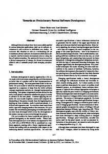
Let us suppose, for example, that a given component Ci offers h>=1 services Sj (j=1…h). The obtained performance results for each Sj are exported, in a parametric form, at the component interfaces, as PerfCi(Sj(env-par)) where Perf denotes the performance index we are interested in (e.g., demand of service, response time and communication delay) and env-par the environment parameters. Let us briefly describe how this approach can refer to a software modeling notation based on RT-UML PA profile. For the component modeling, we refer to [6] where a component is defined as a set of interrelated component forms, each reflecting some aspects of a component during the development lifecycle: component specification, interface, implementation, installed component and component object. Each form can be modeled by a set of UML diagrams as described in [6]. In CB-SPE the component developer can annotate these diagrams following the PA profile. Examples of annotations are the response time (required or measured) of a specific behavior/service, or the host execution demand that in this case will be parametric, or the probability to execute a given service and so on [19]. Then starting from the RT-UML component specification it is possible, by following one of the existing approaches [3,4,8,13,14], to (automatically) derive performance models that are SMs with parametric resource requirements. These results should then be exported at the component interface following the RT-UML syntax, as schematically illustrated in Figure 1. interface Component Client
specification
PAresptimeCi(Sj(env-par))
Component
interface
implementation
PAdemandCi(Sj(env-par))
Input:
set of components with performance parametric annotations on the functionality interfaces (component developer)
Step 1. Step 2. Step 3. Step 4. Step 5. Step 6. Step 7.
Determine the usage profile (system assembler) Component selection (system assembler) Modeling and annotation (system assembler) Best case analysis (automatic) CB-SPE model generation (automatic) Model evaluation (automatic) Analysis of results (system assembler)
Output: selection of the components and modeling of the application with performance requirements satisfied or otherwise declaration of performance requirements unfeasibility Figure 2: CB-SPE at the application layer Let us describe in detail the various steps by referring to a software modeling notation based on the RT-UML PA profile. Step 1.
Determine the usage profile
At this step the system assembler should define the different types of application users and the different use cases. Let us suppose, for example, to have several types of users and a number of use cases, each use case z must be weighted by a factor P(z) representing its usage frequency, as illustrated in [8]. The collection of all the Use Case probabilities (∀z, P(z)) represents the usage profile. This can be modeled following the RT-UML PA profile by use of a high level Activity Diagram (AD) in which each activity models a Use Case and is annotated with a PA attribute modeling its usage frequency.
…
Step 2.
PAdelayCi(Sj(env-par))
The system assembler chooses among the components that offer similar services, those that provide the best performance. In fact, he/she can now instantiate the generic PerfCi(Sj(env-par)) given in the component interfaces, with the characteristics of the adopted (or hypothesized) environment so obtaining a set of values among which the best ones can be selected.
Figure 1:Example of component interface annotations
3.2 The application layer Goal of this layer is to obtain CB applications with the expected performance properties. The system assembler chooses among the available components those that better fulfill the performance requirements. In fact, at this step, the system assembler knows the characteristics of the platform in which the components will be deployed and thus he/she can instantiate the component performance properties given in parametric form. The various component performance properties can now be combined in a system by following the architecture of the application. If, from the model analysis, the system assembler concludes that the performance requirement are fulfilled, he/she can proceed with the acquisition of the components and their assembly, otherwise he/she has to continue searching by repeating these steps, or at last declare the unfeasibility of the performance requirements with the acquisition of components off-the-shelf. Figure 2 outlines the main steps involved in the application of our methodology by highlighting also (in italic) who is in charge of them.
Step 3.
Component selection
Modeling and annotation
The system assembler should describe, by one or more sequence diagrams (SD), the application workflow (the glue). In a CB framework the SD objects represent the components involved, and the SD messages represent the requests of execution of a component service or correspond to information/data exchanged between the components. Moreover the system assembler should construct a Deployment Diagram (DD) modeling the available resources and their characteristics. In this case the nodes of the DD can be associated to classical resources (device, processor, database) and communication means. We note that the system assembler does not have to repeat this step from scratch each time he/she needs to make estimations about an application. The same diagrams can be re-used for similar applications, by only updating the associated parameters. The SD and DD diagrams have to be annotated with the proper performance values and parameters. The system assembler should express, by using a comment-based annotation, the attributes associated with events and actions of the diagram. Fig. 3 and 4 illustrate examples of PA annotations in SD and DD.
n
Comp_A
Comp_B
Perf (appl ) = ∑ pCi * Perf Ci ( S (env )) + K
Comp_C
(1)
i =1
Req1( )
{PApopulation=$Nuser; PArespTime=$K}}
{PAdemand= (‘assm’,mean,1k/v1,
Rep1( )
' u(t)’}
Req2( ) Rep2( ) Req3( ) Rep3( )
Figure 3:Example of an annotated SD For example, considering the SD, the PA attributes in the annotations are: the population, that represents the number of jobs in the scenario, the response time, that represents the application completion time and is one of the expected results. {PAschedPolicy=FIFO PAthroughput=x/sec PAutilization=$util} node1 Comp_C
node1 Comp_A Comp_B
Lan {PAschedPolicy=PS
PAutilization=$util}
Figure 4: Example of an annotated DD Considering the DD nodes, the PA attributes concern the resource scheduling policy (i.e. the strategy by which the resource handles the different jobs), the resource utilization and the resource throughput that represents the amount of work provided per unit of time by a resource belonging to a certain node. Note that the PA attributes of the closed workload will be associated with the first action of the SD; those of the steps will be linked to each of the subsequent message activations; those of the resources will be related to each of the nodes of the DD. Step 4. Best-case analysis In this step we perform a first kind of performance evaluation called best-case analysis. The obtained “costs” correspond to the special case of a stand-alone application where the application under study is the only one in the execution environment (therefore there is no resource contention). Hence these results provide an optimal bound on the expected performance for each component choice, and can help the system assembler in identifying a subset of the components that possibly deserve further investigation in the more realistic setting of competition with other applications. Let us suppose that the application involves n components Ci and that either h=1 (∀ Ci) or the application uses only one service at a time for each Ci. Then the performance of the application for a given index is:
where pCi denotes the usage frequency of the component Ci (and all pCi, i=1…n, must sum to one) and is obtained by combining the information derived by the usage profile and the information contained in the SD [23]. Let us suppose, for example, that the application is modeled only by the SD in Figure 3. Then the component usage frequency can be computed as the ratio between the number of interactions that require some services to the component and the total number of interactions. For example the SD of Figure 3 leads to pA=3/6, pB=2/6 and pC=1/6. K is a constant denoting the delay due to communication. Similarly, we can derive an optimum bound when the application requires to each component a number h>1 of services. Step 5. CB-SPE model generation A more realistic performance model should consider resource contention and communication costs. To this end we consider QN models, where the service centers model both the environment resources with the relative characteristics that become the rate (speed) of offered service and the communication channels with the associated delay, while the jobs in the network model the application activities with the related demands of services. The performance indices obtained from the analysis of the queueing model take into account resource and channel contention and have as optimal bounds the values obtained from the application of formula (1). The queueing model can be (automatically) obtained by applying the method proposed in [3,8], where the application dynamics is the SM based on EG and the components and resources represent the MM based on QN. Step 6.
Model evaluation.
The QN model obtained in the previous step can be solved to obtain several results such as: the completion time for the application (or for a single application activity), the resource utilization, the better resources distribution with respect to a certain completion time and so on. Step 7.
Analysis of results
The results automatically obtained in step 6 are analyzed by the system assembler and, if different from those expected (or desired), he/she can go back to step 1 (or 2), modify the settled parameters, and repeat the process until the desired results are obtained or after a while the unfeasibility of the performance requirements is declared. Clearly, the analysis can produce useful indications about how to modify the parameters.
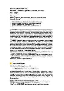
3.3 Automation With reference to the stepwise procedure described above, an automated environment should incorporate a tool fully automating steps 5 and 6 (the SPE related computations), and providing as well support to the other steps, facilitating the RT-UML modeling of the workflow and the resources according to the required formats. To make the SPE calculations, the environment transforms the UML model annotated with performance information into a QN performance model [10], which can be read directly by existing solvers [10]. The environment architecture is illustrated in figure 5. A UML editor (any of the several available) processes the input diagrams and generates an XML file. The
UML to QN transformation component takes in input the XML file and produces as an output a file describing the performance model. Specifically, the QN model structure is generated from the high-level software architecture described in the DD indicating the allocation of software components to hardware devices.
+ RT-UML PA annotations UML tools
UML Model
Analysis of Results
(XMI)
convertor
UML to
Performance
QN
Model
Performance results
QN solver
component
Figure 5: Automated environment The QN model parameters are obtained from detailed models of key performance scenarios represented in the SDs. The derived performance model goes to a performance model solver (QNM analytical solver or simulator) that derives the performance analysis results. Finally the Results Convertor analyses the performance results and converts them back to the UML model in the form of constraints on some PAattribute, thus completing a round-trip tour.
4. Overview of related work In this section we present a short survey of the existing work on performance evaluation of CB systems and on performance modeling using UML and RT-UML based software models. We treat these areas in two separate subsections below, also because to the best of our knowledge, ours is the first attempt to merge them into a unifying framework.
4.1 Performance of CB systems There are not many works on CB performance engineering, due both to the novelty of the topic and to its inherent difficulty. When the emphasis is on the quantitative evaluation of performance, the approach mostly applied is measurement [7,24]. In [24] a discussion is brought of how component-based system properties may influence the selection of methods and tools used to obtain and analyze performance measures. Then a method is proposed for the measurement of performance distinguishing between application-specific metrics (e.g., execution time of various functions) and platform-specific metrics (e.g., resource utilization). The automation of the process of gathering and analysing data for these performance metrics is also discussed. The major drawbacks of this approach are that it is suitable only for already implemented systems and moreover the obtained results do not show general applicability. A different approach that partially overcomes these difficulties is presented in [7] where starting from a specific COTS middleware infrastructure, a first
step empirically collecting performance measures is followed by a second step in which the obtained results are elaborated to extend their validity to a more general setting. The proposed approach also includes: a reasoning framework for understanding architectural trade-offs and the relationship with technology features; and the derivation of a set of mathematical models describing the generic behavior of applications using that specific COTS technology. An inherent limitation of this approach is that it leads to sound results only for a specific platform. A different approach targeted to include predictability in performance behavior of CB systems is presented in [15]. The basic idea is that the “behavior of a CB system must be compositional in order to be scalable” and this requires (as in our approach) to include also performance specifications in addition to descriptions of component functional behavior. The paper outlines how classical techniques and notations for performance analysis are either unsuitable or unnatural to capture performance behaviors of generic software components, and explains that “performance specification problems are so basic that there are unresolved research issues to be tackled even for the simplest reusable components”. A first attempt towards a compositional approach to performance analysis is then presented mainly based on the use of formal techniques. However, as the authors claim, an engineering approach to predictability on performance is a necessary ingredient to ensure predictable components. A very interesting line of research is proposed in a recent paper by Hissam et al [9], where it is presented a prototype prediction enabled technology, called PECT, that integrates component technology with analysis models. The main goal of PECT is to enable the prediction of assembly level properties, starting form certifiable components, prior to component composition. Finally, a different, mainly qualitative, approach to the performance predictability/analysis of CB systems is undertaken in [2,21], where the affinity between Software Architecture (SA) and Software Component (SC) technology is outlined and exploited. This affinity is related to different aspects: (i) the central role of components and connectors as abstraction entities, (ii) the correlation of architectural style and component model and frameworks, (iii) the complementary agendas followed by the SA and SC technologies: enabling reasoning about quality attributed, and simplifying component integration. Therefore, the basic idea underlying these works is to develop a reference model that put in relations the key abstractions of SA and CB technology and then to adapt and apply some existing SA analysis methods, such as ATAM, QADP, etc.
4.2 Performance from UML and RT-UML based models In the last years several papers have presented methodologies for the generation of performance evaluation models starting from UML diagrams, possibly augmented with suitable performance annotation ([8], papers in [22]). These papers consider different target models, spanning simulation models, Petri nets and QNs. Recently, the growing interest in SAs has brought to extending performance model generation to also encompass the SA concept, with particular emphasis given to the impact on performance of the software organization into components and patterns of interaction (papers in [22]). In all these papers the target performance model is a QN. As already stated, the adoption as a
standard of the PA profile (see Section 2.2) is quite recent and therefore there are very few papers dealing with RT-UML based software systems. Selic in [14, 20] provides a general framework (and relative guidelines) for the automatic generation of a performance model starting from RT-UML diagrams. A first attempt to use the recently adopted standard UML Performance Profile [19] is presented in [13]. This paper proposes a graph grammar-based method for the automatic transformation of a UML model annotated with performance information into a Layered Queueing network (LQN) performance model. The LQN structure is generated from the high level SA showing the architectural patterns used in the system, and from Deployment Diagrams indicating the allocation of software components to hardware devices. The LQN model parameters are derived from information relative to key performance scenarios. A completely different application of the PA profile has been proposed in [3,4], where performance engineering is applied to aid the project manager in making schedule predictions and in optimizing personnel utilization during software development. In this context the project teams are assimilated to the processing elements of a performance model, and their activities to the tasks to be accomplished within established time intervals. Then by use of the proposed approach different workflow assumptions can be explored and their consequent outcomes automatically derived. A front-end interface based on a subset of Real-Time UML is provided to allow people not expert of performance modeling notations to apply the approach.
5. Conclusions This paper presents a starting point towards an engineering approach to encompass performance validation in CB systems on the basis of the architectural specification. We have defined an original approach, called the CB-SPE, that relies on, and adapts to a CB framework, the concepts and steps of the well-known SPE technology and uses for modeling the standard RT-UML profile, reshaped according to the CB principles. An outline of the automated environment realizing CB-SPE is also given. Future work includes the automated environment implementation and its application to case studies coming from the industrial world.
6. References [1] Bachman F., et al., Technical Concepts of Component-Based Software Engineering, T.R. CMU/SEI-2000-TR-008
[2] Bass L., Klein M., Bachman F., Quality attributes design primitives. Technical note CMU/SEI- 2000-TN-017
[3] Bertolino A., Marchetti, E., Mirandola, R. Real-Time UMLbased Performance Engineering to Aid Manager's Decisions in Multi-project Planning, in [22] [4] Bertolino A., et al., Software Performance Measures to Assist Decision Makers within the Rational Unified Process, in Proc. of 12th IWSM 2002, Magdeburg, Oct. 2002
[5] Bertolino A., Mirandola R., Modeling and analysis of nonfunctional properties in component-based systems, to appear Tacos 2003 [6] Cheesman J., Daniels J., UML Components, A simple process for specifying component-based software, Addison Wesley, 2001 [7] Chen S., Gorton I., Liu A., Liu Y. Performance prediction of COTS Component-based Enterprise Applications, ICSE Workshop, 5th CBSE 2002 [8] Cortellessa, V., Mirandola, R. PRIMA-UML: a Performance Validation Incremental Methodology on Early UML Diagrams, Science of Computer Programming, 44 (2002), 101-129, July 2002, Elsevier Science [9] Hissam S.A., et al., Packaging Predictable Assembly, CD 2002, LNCS 2370, pp108-124. Springer Verlag 2002. [10] Lavenberg S.S. Computer Performance Modeling Handbook. (New York, 1983), Academic Press [11] Model Driven Architecture, A Technical Perspective.' doc. n. ab/2001-01-01, n. ormsc/2001-07-01 [12] Meyer B. Applying ‘Design by Contract’. Computer, 25 (10), Oct. 1992, 40-52 [13] Petriu D.C., Shen H. Applying the UML Performance Profile: Graph Grammar-based derivation of LQN models from UML specification. LNCS 2324, Springer Verlag [14] Selic B. Performance-Oriented UML Capabilities. Tutorial talk in [22] [15] Sitaraman M., et al., Performance specification of software components. In Proc. of SSR '01, p. 310. ACM/SIGSOFT, May 2001 [16] Smith, C.U. Performance Engineering of Software Systems, Addison-Wesley, 1990 [17] Smith, C.U. and L. Williams. Performance Solutions: A practical guide to creating responsive, scalable software, Addison-Wesley, 2001 [18] Szyperski C. Component Software: Beyond Object-Oriented Programming, Addison Wesley, 1998 [19] UML Profile for Schedulability, Performance, and Time Specification: http://cgi.omg.org/docs/ptc/02-03-02.pdf [20] UML Documentation version 1.4 Web Site. On-line at
http://www.rational.com/uml/resources/documentation/ [21] Wallnau K., et al. , On the relationship of software architecture to software component technology. In Proc WCOP6, 2001. [22] WOSP2002, Proceedings of the Third Int. Workshop on Software and Performance. ACM, 2000 [23] Yacoub S., Cukic B., Ammar H.H Scenario-based reliability analysis of component-based software, in Proc. of ISSRE’99, Boca Raton, Florida, 1-4 Nov. 1999 [24] Yacoub S. Performance Analysis of Component-Based Application. In Proc. of the 2nd, p.299-315.