Sep 28, 2004 - 229-239,2003,. F. Silva, J. Tenreiro Machado, âEnergy Aoalysis Duriog Biped. Wakingâ, Pme EEE Int. CO*{ Robotics m d Automotion, pp. 59-.
Proceedings of 2004 IEEURSJ International Conference on Intelligent Robots and Systems September 28 - October 2,2004, Ssndai,Japan
Towards Force Interaction Control of Biped Walking Robots F.M.Silva Dept. of Electronics and Telecomunications University of Aveiro 3810-193 Aveiro, Portugal
J.A. Tenreiro Machado Dept. of Electrical Engineering Polytechnic Institute of Port0 4200-072 Porto, Portugal
Absmcl - This paper addresses the problem of modelling and control of a biped robot by combining Cartesian-based position and force control algorithms. The walking cycle is divided in two phases: single support, in which one leg is in contact with the ground and the other leg swings forward, and double suppo% la which the forward leg absorbs the impact and gradually accepts the robot's weight. The contact of the foot with tbe constrained surface is modelled through nonlinear spring-damper systems. The proposed control approach is based on simple motion gods taking Into account the reaction forces between the feet and the ground. The control algorithm is tested through several experiments and its robustness is dlscnssed.
mechanism-environment interactions. The ground reaction forces are the key element through which new control strategies are proposed to provide the level of compliance, adaptation and dynamic stability required for walking in different contexts. In this line of thought, the remainder of the paper is organised as follows. Section 2 describes briefly the implementation of both biped and environment models. Section 3 is dedicated to control issues and the implemented strategies. Section 4 studies the application of the proposed algorithms and presents simulation results. Section 5 concludes this paper and outlines the perspectives towards future research
I. INTXODUCTION Many aspects of modem life involve the use of intelligent machines capable of operating under dynamic interaction with their environment. In the pursuit of solving control problem, a growing community of researchers is working towards a better understanding of machines that can balance, strike purposively and coordinate multiple degrees of fieedom [I]. Walking robots exhibit complex kinematic and dynamic phenomena that make difficult their analysis and control. The major problem associated with bipedal systems are the high-order, highly coupled nonlinear dynamics and the discrete changes in the dynamics due to the nature of the waking gait. Furthermore, the degree of freedom (dot) formed between the foot and the ground surface is underactuated [2], 131 affecting the postural stability. There bas long been a dichotomy in styles used in designing and implementing biped robots. Many articles about biped locomotion focus on technological applications: Honda P2 [4], Waseda WL-12 [5] and University of Tokyo H5 [6]. In each of these robots, a fairly accurate dynamic model is used to compute dynamically admissible joint trajectories offline. These planned trajectories are then played back dwhg walking and modified online through feedback in order to maintain stability. Other research groups use heuristic methods of control: MIT Spring-Flamingo [7] and MEL Meltran [8] are two remarkable examples. Instead of pre-computing joint trajectories, simple feedback rules are wed online to control the robots. Additionally, the exploration of the specific characteristics of biped walking is the key challenge to closely relate the planning and motion control problems. Based on the latter approach, this paper emphasis the f u n c t i o ~ lproperties that emerge from the interaction between the robot and its environment. This means that the competence or "intelligence" is located into the
0-780384654/041$20.00 82004 IEEE
11. MODELLING OF BIPED WALKING A. D y m m i a of rhe EipedRobot
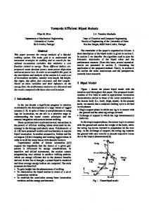
The planar biped model consists of two lower limbs and an upper body (trunk and pelvis), with a total of 7 degrees of fieedom (Fig. I). The biped robot is a mechanism that repeatedly interacts with the environment through their feet. In this line of thought, the dynamic equations of motion are derived assuming the contact of both legs with the ground
-4f" 4.f"
(1) r = f f ( q ) i+ c(q,d + g ( q ) where r is the vector of generalised torques, q is the vector of joint coordinates, H ( q ) is the inertial matrix, c(q,q) , is the vector of centrifugaUCoriolis torques and g(q) is the vector of gravitacional torques. The transpose of the Jacobian matrices, J,' and -I:, transforms the forces that
(fL)
the environment exerts on the right (fR)and left foot into joint torques. The planar robot comprises a total mass of M = 70 kg and a maximum height of L = 1.4m (see Table I).
2568
-
5 7
Figure 1. Planar biped model.
TABLE I
B. Environmenl Model and Sensorial Requirements The contact of the foot with the constraint surface is modelled through a nonlinear springdampcr system in the horizontal and vertical directions [9]. The tangential and normal reaction forces applied to the foot are computed as: f t
= -K,(x-xo
f. = - K , b - ~ o
I-4
b-yo
)-AYb-yo
YL
”d
(2)
I_^
Figure 2. Envi”sn1
where K, and K,, are the spring stifiess, 1, is a A,, and are variables that depend on the Penetration depth and (XO,YO) are the coordinates ofthe foot at the moment of its initial contact (see Table U). TABLE U E m o ” ~PARAMETERS.
-
b
model.
Recent advances in integrative studies of locomotion have revealed general principles and simple rules that give rise to reach behaviors. Remarkably, these high-level principles and heuristics are colle&ve or emergent properties of biped walking arising &om the interactions among the pieces on the “chessboard”. Bearing this facts in mind, the locomotion process should be explored in function of two main players - robot and environment and the relations established along their natural and repetitive interactions [lo]-[131. A. HybridPosilion-Force Confrol
The blocks diagram of the proposed control architecture is shown in Fig. 3. Its structure takes the form of a hybrid positioniforce algorithm changing between force control for the leg@) in contact with the ground and position control for the leg moving in the &ee space. It is assumed the existence of two contact points located nemotion planning is accomplished by prescribing the in the extremities ofthe foot (at the toe and across the heel), cartmian trajectories of the hip and the lower extremity of where two force sensors are inserted (see Fig. 2). the swing leg. This leg is trackcontrolled to place the foot on the ground with zero velocity in order to reduce the In. C O ~ O L A R C H I T E C T U R impact effects. On the other hand, when the swing foot The essence o f h ” t i o n is to transport the upper body contacts the ground, additional control efforts are used in fiom an initial position to a desired one throughout the both legs to stabilize the post-impact phase. During the action of the lower limbs. Conceptually, this goal requires double support phase the forward leg gradually accepts the the considemtion of three problems: postural stability, robot’s weight to provide for a smooth transfer of support. aerial motion and contact with the ground. Moreover, it is In what concerns the upper body, two goals should he necessary to combine, simultaneously, different Control achieved. 1) the upright stability of the pelvis; and 2) the mechanisms depending on the walking phase. improvement of both the dynamic stability and the forward progression regulation by exploiting the b u n k ‘ s inclination.
2569
variables to be controlled are the normal reaction forces across the heel and at the toe,f&, andf,,=, respectively. In other words, the resultant normal force f," and the centre of pressure COP.The corresponding references are generated automatically in result of demands (motion goals) imposed to the upper body section. These are the variables that some force control law must follow. The force errors measured in each extremity of the foot can be transformed into joint torques by using the transpose of the Jacobian matrices. The ground reaction forces combine botb the gravity acting on the system and the accelerations of all body segments. In this perspective, the desired normal force is computed on-line as the sum of the robot's weight with a compensation term:
Figurr 4. Basic principle of the eantrolla
The relevant aspects of the GO-FIC are the minimal dependence on planned variables and the consideration of the reaction forces at the feet extremities on the control algorithm. As illustrated in Fig. 4, the biped robot "feels" the forces while the controller distributes them as driving torques that regulate the desired motion of the upper body. The interaction forces are the key element through which new control strategies are proposed to provide the required level of compliance, adaptation and dynamic stability. The difficult relation between motion planning and dynamic stahility justifies a new line of thought: the skill of locomotion must emerges from the physical interaction between the machine and the environment itself. According to this principle, it is convenient that the controller may, in each moment, establish a relation between the desired mobility (measured at the hip) and the postural stability (measured at the ground). In this context, it is up to the degrees of freedom nearest to the ground - ankle and knee - to assnre the mobility and stability of the system, and to the degrees of freedom more distant from the ground - hip and bunk - the main role of compensation. A question that may brought up is to know how to conciliate these two imperatives - mobility and stability that in many circnnstances are contradictories. On the one hand, whenever the mobility goals can be achieved, it is advantagous to maximise the energetic efficiency. On the other hand, it may be necessary to sacrifice tbe mobility goals (e.g., step length and/or forward velocity) to assnre the dynamic stability. In this line of thought, the mobility signals are not commands but indications sent to a mechanical system possessing its own behaviour. The rotational equilibrium of the foot is the major factor of postural instability in legged robots. Constrained forces at both feet are controlled such that stable contact is preserved between the feet and the ground
f."/ = BW + Here
fn4
k i(yrf- y,, )+ K i ($rf- j , )]
(4)
is the reference normal force, BW is the total
system's weight,
yy and y ,
are the desired and real hip
vertical position, j y f a n d j , are the corresponding velocities, and K{ and K/ are the position and velocity gains. This means that vertical errors at the hip are transformed into modifications of the reference force around its average value. At the same time, there are different mechanisms to regulate the progression of the robot during the single support phase. One of them consists of moving directly the centre of pressure located under the foot (e.g., ankle actuation). For example, if the COP moves forward (hack) the robot slows down (up) in order to remain adapted in a variety of contexts. In this line of thought, the desired location of the centre of pressure C O P is obtained directly as function of the horizontal errors measured at the hip:
cop'@= K C O P ( x r f - X * ) + K y ( x y -x*) where COPef is the reference centre of pressure, x,,
I;@
(5) and
are the desired and real horizontal hip positions, xh"/
and i,are , the corresponding velocities, and
Ky
and
K,? are the position and velocity gains. This means that the reference COP is actively used to calculate the distribution of the total reaction force along the extremities of the support foot. In the same way, the posterior (anterior) inclination of the body section allows the centre of mass to move forward (back) making it faster (slower) than if it remains upright. Therefore, one of the terms affecting the torque of the tnmk > 0 and f,. > 0 (3) joint, r, ,uses a PD control law defined by: where f,, and f, are the normal ground reaction forces rp"s = K r x'd - xh K: (xTf (6) at the toe and across the heel.
L
(
B. Force Inferaction Control
)+
x~)
where Ki and K: are the position and velocity gains.
Simultaneously, the postural stability imposes limitations The proposed control architecture enables the active steer in face of changing conditions (e.g., load or environment) to the trunk motion: its inclination must remain within a by combining both force feedback with online pattem- limited range of the angular space and, when operating in modifications. Considering the support leg, the two steady state, it must converge to a limite cycle.
2570
The control laws are designed independently: the position control law consists of a PD action and the force control law consists of a PI action. It is introduced an enhancement to the PI force controller by adapting its gains during the DS phase in accordance with the distribution of forces between legs
IV. SIMIJLATION RESULTS
Figure 5. Conhol rtrucfure ofthe m
d section
In this regard, the control structure of the trunk section integrates another block associated with the postural stability (Fig. 5). It is the sum of both components that actuate over the system:
r, = Ip"p + I,?+"
(7)
The control scheme is tested through several experiments and its effectiveness and robustness is discussed. The motion planning is accomplished by prescribing the Cartesian trajectories of the hip and lower extremity of the swing leg. In this sense, the biped motion is characterised in terms of a set of locomotion variables (refer to Fig. I), such as step length S,, hip height Hh, hip ripple H, hip pitch angle 4,foot clearance F, and forward velocity V, [14]. The next simulations are carried out assuming the locomotion variables as presented in Table III.
In what concem the double-support (DS) phase, the question is how to solve the force distribution between legs TABLE Ill LocoMOTlON VuU*BLES. that allows a smooth transition of support. Given the virtual references in (4) and (5), a simple method is used in which the legs gradually trade role. A linear function u