UIs are no longer confined to a unique desktop, but they ... A MDE FRAMEWORK FOR PLASTIC UIS .... Sottet, J.S., Calvary, G.,Favre, J.M., Toward Model.
Towards Mapping and Model Transformation for Consistency of Plastic User Interfaces Jean-Sébastien Sottet, Gaelle Calvary, Jean-Marie Favre University of Grenoble 385, rue de la Bibliothèque 38403 Grenoble Cedex 9 {jean-sebastien.sottet, gaelle.calvary, jean-marie.favre}@imag.fr (+33) 4 76 63 56 87 Model Driven Engineering (MDE) [2] advocates the systematic use of “productive” models that can be processed by the machine. Full engineering processes are described by explicit models connected by explicit networks of mappings and transformations [3].
ABSTRACT
Developing many variants of a same User Interface (UI) on different platforms is challenging. Plasticity is even more demanding. In Human Computer Interaction, plasticity denotes the capacity of a UI to withstand variations of context of use while preserving usability. A context of use is a triplet < user, platform, environment >. Plasticity raises many issues both at design time and run time. This paper shows how Model Driven Engineering (MDE) can be used for reasoning at different levels of abstraction when developing and executing a UI. These levels of abstraction define different perspectives on a same UI. This paper shows how MDE based mappings are powerful for ensuring consistency between these perspectives both at design time and run time.
This paper investigates MDE for the development and execution of plastic UIs. In HCI, plasticity denotes the capacity of a UI to withstand variations of context of use while preserving usability. A context of use refers to the triplet . In ubiquitous computing, the context of use may be various, variable and unforeseeable. For instance, from a platform perspective, UIs are no longer confined to a unique desktop, but they can be distributed or migrate among a dynamic set of interaction resources. As a result, UIs must be gracefully remold in order to adapt to the current context of use. While product line approaches deal with the production of variants of UIs (e.g. a UI specifically crafted for PC or PDA), plasticity is even more challenging coping with the change of the context of use. Adaptation must be done in an opportunistic manner while preserving usability.
Author Keywords
Model Driven Engineering, Mapping, Model transformation, Plasticity, Adaptation to the context of use. ACM Classification Keywords
H5.m. Information interfaces and presentation (e.g., HCI): Miscellaneous.
In both product line and plasticity, one major obstacle is to check and maintain consistency between the UI variants. While code-centric approaches might be suited for the development of simple and single UIs, they simply fail for plasticity. Our vision is to model an interactive system at different levels of abstraction and dynamically maintain the mappings between these levels for measuring consistency and sustaining adaptation at run time.
INTRODUCTION
The need of models in Human Computer Interaction (HCI) has been recognized for long. Nevertheless full automatic generation of User Interfaces (UI) rapidly shows its limits [1]. That does not mean that model-based techniques are not valuable, but that they have to be further explored. On one hand, reverse and cross engineering should be investigated like forward engineering. On the other hand, models should live at run time instead of being limited to the design time. One major advantage is to embed the design rational at run time, making possible adaptations when the context of use changes.
This paper is twofold. Section 1 introduces a MDE framework for sustaining our vision. Section 2 focuses on mappings and transformations for ensuring consistency when adaptation occurs. A MDE FRAMEWORK FOR PLASTIC UIS
The core concepts of MDE are development processes, models and metamodels, mappings and transformations. This section focuses on development process, models and metamodels. Mappings and transformations are discussed in next section.
1
Hypotheses Property
Context of Use User
M1
M2 -Usr
Environment
Property
Domain Concept
Task
Workspace Interactor
M2-Plf
M2-Env
M2 -Ppt
M2 -Cpt
M2-Tsk
M2 -Wks
M1 -Usr
M1-Plf
M1-Env
M1 -Ppt
M1 -Cpt
M1-Tsk
M1 -Wks
M1 -Usr'
M1-Plf'
M1-Env'
M1 -Ppt'
M1 -Cpt'
M1-Tsk'
M1 -Wks'
M1-Int
M1 -Usr''
M1-Plf''
M1-Env''
M1 -Ppt''
M1 -Cpt''
M1-Tsk''
M1 -Wks''
M1-Int'
Model transformation
M2
Platform
Design
Program
M1-Prg adhoc UI programming
Model Driven Engineering Model Driven Engineering
of Classical User Interfaces
of Plastic User Interfaces
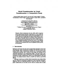
Figure1. A MDE Framework for the development of UIs Development process
Current industrial practices are still mostly code-centric (right bottom of Figure 1). Conversely, MDE processes are based on successive refinements of models, integrating new information at each step [5]. They consist in reifying models step by step from an entry point (in a top-down approach, the task model) until reaching the final running program. Typical forward development process starts with the end user and the domain models. Then, based on a design know-how, the UI is refined in terms of workspaces, interactors and finally program elements dependent on the target platform and the available libraries. As suggested in Figure 1, models are revised at each step to take into account the constraints related to the current level of abstraction (for instance, M1-Task revised in M1-Task’ and M1-Task’’). Product line processes favor both the factorization of the product common parts and the decoration (annotation) of its specific parts. Plasticity goes one step further for coping with the change of the context of use. New (meta)models are required as explained below.
Concept. A concept is an entity “relevant to users to accomplish tasks in a particular domain”. A concept model can be described as an UML class diagram.
•
Workspace. A workspace enables a “set of logically/semantically connected tasks. In graphical UIs, a workspace can be mapped onto a window, a set of panels”.
•
Interactor. An interactor is “an abstraction of a software component that allows users to manipulate and/or observe domain concepts and functions”.
•
Program. The program is “The UI produced at the very last step of the reification process supported by a multi-target development environment. It is expressed as source code”.
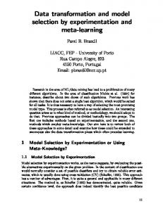
A simplified backbone of four (under elaboration) metamodels is provided in Figure 2. The mappings will be discussed in next section. As explained in CAMELEON [5], these (meta)models are not sufficient for plasticity. New (meta)models are introduced to describe both the context of use and the expected usability.
(Meta)Models for UI engineering
As explained in CAMELEON [5], five (meta)models structure the development process of classical UIs. •
•
Task. A task refers to “a goal, together with some procedure or set of actions that will achieve the goal”. From a MDE perspective, a task model can be described as a tree made of binary and unary operators.
•
2
User. The user is “the archetypal set of end-users envisioned for the interactive system”. This model captures general information (e.g. age, gender,…) as well as skill level.
Figure2. A simplified backbone of four metamodels.
•
Environment. The environment refers to “the physical setting where the interaction takes place. It can be modeled as the set of objects, persons and events that are peripheral to the current activity but that may have an impact on the system and/or users behavior”. From an engineering perspective, the environment can be modeled as a graph of contexts and situations [9].
composable and extendable transformations. The designer selects and if necessary tunes the appropriate transformations. If no transformation is available then a new one can be written thanks to transformation languages. It can be added to libraries. Quite often, transformation engines are limited to the metamodels they manipulate. HCI could take benefit from software engineering transformation environments not devoted to HCI.
•
Platform. The platform denotes “the set of physical and software resources that function together to form a working computational unit whose state can be observed and/or modified by a human user. It may be an elementary platform or a cluster of platforms”. Platform modeling is a core issue in MDE.
•
Usability. Usability refers to “the extent to which a product can be used by specified users to achieve specified goals with effectiveness, efficiency and satisfaction in a specified context of use”. Existing frameworks (e.g. Scapin & Bastien [7], IFIP [8]) enumerate a set of properties without localizing them on the map of metamodels (like Figure 2). While some properties are confined to a unique (meta)model (for instance, the ergonomic consistency that is computable at the interactor level), some others depend on the mappings between several metamodels.
We use generic MDE techniques and extendable libraries of transformations and metamodels. While emerging standards for expressing MDE transformations are under active development (e.g. QVT), we investigate [4] the appropriateness of a generic MDE transformation language for plasticity. This language should be able to describe the mappings and transformations associating elements of metamodels (for instance, the association Class-Task connecting together the metamodels Concept and Task in Figure 2). Thanks to such a generic transformation language, we provide libraries for sustaining forward engineering and plasticity. Now we envision the description and dynamic tracking of consistency by mappings and transformations. Mappings and consistency
The mapping problem has been defined by Puerta and al [10]. It states that mappings are the key for acceptable model based UIs. Some tools like DynaMo-Aid [11] demonstrate the benefit of mappings at design time. The main idea is to ensure consistency between models when a modification occurs thanks to an association (mapping) that is aware of the dependencies between the connected models.
MAPPINGS AND TRANSFORMATIONS FOR CHECKING AND ENSURING CONSISTENCY
Without mappings and transformations, models would be isolated. In this area, MDE promotes libraries of small
3
Mappings connect together a set of metamodels, at least two. Each mapping describes its role (for instance, the Task t manipulates the Concept c) and the cost/benefit ratio for ensuring its role (for instance, the interaction length for performing the task). By nature, the role can deal with either functional or structural concerns.
to avoid the production of ad-hoc and technological domain dependent solutions. One open issue is the observability and control of mappings and transformations by the end user. We call this UI meta-UI. REFERENCES
1. Myers B., Hudson S.E., Pausch R. "Past, Present, and Future of User Interface Software Tools", Transactions on Computer-Human Interaction (TOCHI), Vol 7, Issue 1, 2000
A functional mapping is a coupling between models that produces a new function. For instance, a label “Name” coupled with an input field provides the end user with the function “Specify name”. For plasticity, the coupling with the physical entities (mouse, keyboard, table, etc.) is a key issue as the user evolves in a changing environment. These functional mappings will help when reasoning about consistency at a structural level.
2. Planet MDE, "A Web Portal for the Model Driven Engineering Community" http://planetmde.org 3. Favre J.M., "Foundations of Model (Driven) (Reverse) Engineering", Dagsthul Seminar on Language Engineering for Model Driven Development, DROPS, http://drops.dagstuhl.de/portals/04101, 2004
A structural mapping links together models in order to propagate any relevant modification that occurs in one model to the connected models. Let’s provide two examples: one exogenous, the other one endogenous. Deleting a Task t should suppress the corresponding interactors (exogenous). Ergonomic consistency calls for homogenous presentations. As a result, interactors should be compliant with the neighbouring interactors (endogenous). Whatever the mapping is (endogenous versus exogenous), it should express its elasticity to describe and deal with the modifications it is able to support.
4. Sottet, J.S., Calvary, G.,Favre, J.M., Toward Model Driven Engineering of Plastic User Interfaces. International workshop on Model Driven Development of Advanced User Interfaces, MDDAUI, Jamaica, 2005. 5. Calvary G., Coutaz J. Thevenin, D. Limbourg, Q., Bouillon, L., Vanderdonckt J. "A Unifying Reference Framework for Multi-Target User Interfaces, Interacting With Computers, 2003 6. Demeure, A., Calvary, G., Sottet, JS.,Vanderdonkt, J. A Reference Model for Distributed User Interfaces TAsk MOdels and DIAgrams for user interface design, Gdansk, 2005
Consistency Driven Transformations
The core idea is to drive the transformations by the information embedded in the functional and structural mappings in order to ensure consistency. When the context of use changes, the UI has to be adapted with respect to consistency. This means morphing the network of models without breaking the mappings, i.e. staying within the elasticity domain of the mappings. Advances in graceful degradation [12] are relevant in this area.
7. Scapin D., Bastien, C.H., "Ergonomic Criterias for Evaluating the Ergonomic Quality Interactive Systems." Behaviour and Information Technologies, Vol 16, 1997 8. Abowd G., Coutaz J., Nigay L., "Structuring the Space of Interactive System Properties", Proceeding of the IFIP, 1992. 9. Crowley, J., Coutaz, J., Rey, G. , Reignier, P., Perceptual Components for Context-Aware Computing, UbiComp 2002:, Göteburg, Sweden Sept./Oct. 2002
The mappings should either embed transformations to maintain consistency (close transformations) or be able to invoke external transformations (open transformations). Of course, mappings have to describe their open/close capacities.
10. Puerta, A., Eisenstein, J. Toward a General Computational Framework for Model-Based Interface Development Systems. International Conference on Intelligent User Interfaces, Los Angeles 1999.
CONCLUSION
Models are not new in HCI but they were limited to a poor forward engineering disappointing the end user by a lack of quality. In this paper, models are revisited promoting a dynamic network of models in which mappings and transformations play a central role. They support the description and management of consistency. Transformations are invoked to recover consistency. Following this vision, we are investigating MDE principles
11. Clerckx, T., Luyten, K., Coninx, K. The Mapping Problem Back and Forth: Customizing Dynamic Models while preserving Consistency. TAsk MOdels and DIAgrams for user interface design, Prague, 2004 12. Florins, M., Vanderdonkt, J. Graceful Degradation of user Interfaces, Intelligent User Interfaces, ACM, 2004
4