Towards Model Transformation in Generated Eclipse ... - CiteSeerX
Recommend Documents
ATL: a model transformation language and its execution environment based on the Eclipse framework. ATL tools provide support for the major tasks involved in ...
UIs are no longer confined to a unique desktop, but they ... A MDE FRAMEWORK FOR PLASTIC UIS .... Sottet, J.S., Calvary, G.,Favre, J.M., Toward Model.
if the property has a relation owningClass to a class. When the .... Professor:Entity name:Attribute. Student:Entity examines:Relationship name name. Prof~Prof ... domain model in abstract syntax visualized as an UML object model. As one can ...
Aug 3, 2015 - the behavior of an automatic banking machine and a control system of an ... In the simulation area, the Discrete Event System Specification ...... to download the full definition of the rules. ...... [62] J. Banks, J. S. Carson, B. L. N
Aug 30, 2007 ... The Table to TabularHTML example describes a transformation from a ...
example-Table .ecore example-HTML .ecore. cT. cT example .html.
ware development process where quality assurance of the overall software product considerably relies ... ware development. A typical ..... [Rie96]. Arthur J. Riel.
plant biotechnology (McBride et al., 1994, 1995; McBride and Stalker, 1999; ..... After washing, the membrane was developed for about 1 night on Biomax-Film.
focused recently. Model transformation problems can be formulated as graph ..... graph transformation engine can also be used by a Java API and thus, can be.
Model transformation problems can be formulated as graph transformation .... system GT S = (T,R) consisting of a type graph T and a set of transformation rules R. The abstract syntax graphs of the source models can be specified by that subset ...
The result is an extensible model which could lead to a common view for automated mapping with. CIDOC CRM. Hence, it promotes integration and exchange of.
We would like to thank Marcos Didonet Del Fabro, Freddy Allilaire, David. Touzet, Ivan ... [5] Gamma, E., Helm, R., Johnson, R. and Vlissides, J. (1995). Design ...
Model transformation is one of the key elements in Model Driven Engineering ... design decisions which span all languages in the family, and language interoper- ... Type name : String method 1. VariableDcl. Property name : String. Classifier ..... ac
Sep 7, 2007 - Felix Klar, Alexander Königs, Andy Schürr. Technische Universität ..... link type (ClassToTable in the resulting package) would re- side in the ...
in meaningful ways, so changes in one layer can rip- ... value of business solution implementation. .... for the query would be constructed by finding all con-.
position of model transformations sequences (model trans- formation workflows) up to now ... tions of model transformation chain [25], composition of model transformations [16] ..... have to interact to create the final product. Thus, a clear in-.
Aug 15, 2003 - it helps test and debug evolved applications. We ... Eclipse is a powerful interactive develop- .... 5) To support GUI and non-GUI application.
Oct 11, 2004 - It is also between 2 to 20 times more efficient than that produced by current ...... and Faure, C. 1998. Sparse Jacobean computation in automatic.
such as MetaEdit+ [4], GME [5], and ATOM3 [6], appeared around 2000 (the first
version of ... Both are based on Eclipse and use GEF as a drawing engine.
Philip Clarkson and Tony Robinson. Cambridge University Engineering Department,. Trumpington Street, Cambridge CB2 1PZ, UK. fprc14,[email protected].
This manual provides information on the Eclipse® trans- mitter. It is important ...
included in the Complete Installation section of this manual. Conventions Used ...
cations a number of simplifying services to aid implemen- tation ... services are worked around, or used only in certain con- .... [25] Tata Consultancy Services.
Data transformation and model selection by experimentation and meta-learning. Pavel B. Brazdil. LIACC, FEP - University of Porto. Rua Campo Alegre, 823.
Homepage: http://tfs.cs.tu-berlin.de/emftrans ... To include this update site in your ... Now make sure your new entry is selected in the list of update sites and ...
lated into C code. Compared to the AToM3 .... simulation, a unique Timer object keeps track of the current simulation time. (current attribute) and the final time ...
Towards Model Transformation in Generated Eclipse ... - CiteSeerX
grammars [1], which extend grammar concepts from textual languages to di- ... model transformations specified by means of graph transformation rules [9].
GraMoT 2005 Preliminary Version
Towards Model Transformation in Generated Eclipse Editor Plug-Ins Karsten Ehrig 1 , Claudia Ermel 2 , Stefan H¨ansgen 3 Institut f¨ ur Softwaretechnik und Theoretische Informatik Technische Universit¨ at Berlin Germany
Abstract With the growing importance of model-driven development, the ability of transforming models into well-defined semantic domains becomes a key to automated code generation or verification in the software development process. In this paper, we describe a high-level concept for specifying model transformations by means of typed, attributed graph transformation at the level of formal visual language specifications for the source and the target language. At the implementation level, a graph-transformation based generator of visual editor Eclipse plug-ins from formal visual language specifications has been developed. On the basis of this generator we discuss concepts for an implementation of the presented model transformation concepts and for an integration with the generated Eclipse plug-ins. We explain the concepts for model transformation and their implementation along a concrete model transformation from activity diagrams to Petri nets. Key words: model transformation, Eclipse, editor plug-in, code generation, graph transformation
1
Introduction
Although visual languages (VLs) are becoming increasingly popular, there are controversial opinions about which notation would be best for describing them. For textual languages, using grammars for the syntax is widely accepted, but visual languages have two major competing approaches. One involves graph grammars [1], which extend grammar concepts from textual languages to diagrams. The other approach, called metamodeling, is based on MOF [12] 1 2 3
Email: [email protected] Email: [email protected] Email: [email protected] This is a preliminary version. The final version will be published in Electronic Notes in Theoretical Computer Science URL: www.elsevier.nl/locate/entcs
¨nsgen Ehrig, Ermel, Ha
and calls for using UML class diagrams to model a visual language’s abstract syntax. While class diagrams appear to be more intuitive than graph grammars, they are also less expressive. Therefore, metamodeling also uses context conditions written in the Object Constraint Language (OCL) [13] that help to overcome the weaker expressive power. The advantage of metamodeling is that UML users, who probably have basic UML knowledge, don’t need to learn a new external notation to be able to deal with syntax definitions. But, however intuitive the metamodeling technique is, using it to define UML is still limited to describing abstract syntax; the problems of diagram representations (concrete syntax) and of defining a formal semantics remain. Model transformations are required, for example, to perform verification or consistency checks on the translated model [9], to simulate the model behavior, or to define code generation from visual models. Automatically executable model transformations specified by means of graph transformation rules [9] have proven to be an adequate approach for the case that the source and the target language are both visual languages. The graphical notation of transformation rules supports an intuitive understanding and the rule-based nature allows the flexibility to exchange and modify rules when the requirements for the mappings change. Especially for model transformations of UML behavioral diagrams (e.g. state diagrams) to Petri nets, there exist approaches based on graph transformation [11,16] with the aim of model validation or verification. Model transformation based on graph transformation allows to check functional properties formally, e.g. to show that the model transformation process terminates [2], and that the computed target model is unique [8]. Recently, a new tool environment, called Tiger [15] (Transformationbased generation of modeling environments), has been developed at the Technical University of Berlin [3,4]. Tiger combines the advantages of precise visual language (VL) specification techniques (offered by the underlying graph transformation engine AGG [14]) with sophisticated graphical editor development features (offered by the Eclipse Graphical Editor Framework (GEF) [7]. Graph transformation is used at the abstract syntax level. Tiger extends the AGG engine by a concrete visual syntax definition for flexible means for visual model representation. From the definition of the visual language, the Tiger Generator generates Java [10] source code. The generated Java code implements an Eclipse visual editor plug-in which makes use of a variety of GEF’s predefined editor functionalities. Hence, the generated editor plug-in appears in a timely fashion. Moreover, the generated editor code may easily be extended by further functionalities. The aim of the work presented in this paper is to integrate model transformation with visual editors generated by Tiger. This integration realizes transformations of diagrams edited using a generated Eclipse visual editor plug-in for the source language to diagrams which may be visualized, further edited and manipulated using a generated Eclipse visual editor plug-in for the target language. 2
¨nsgen Ehrig, Ermel, Ha
The preconditions for this process are the definition of visual language specifications for the source and the target language by typed, attributed graph grammars, and the definition of the mapping between the two languages by a typed, attributed graph transformation system based on a union of the source and target VL specifications. On this basis, the generation of the visual editors and the execution of the model transformation can be performed automatically. The paper is organized as follows: Section 2 gives a conceptual overview how to realize model transformation based on visual language specifications between Tiger-generated Eclipse editor plug-ins. An example is presented in detail in Section 3 showing the source and target visual language specifications for UML activity diagrams and Petri nets, as well as the transformation rules for the model transformation. Section 4 concludes with an outlook on future development directions of Tiger.
2
Model Transformation between Editor Plug-ins
In this section we present a concept for model transformation by graph transformation rules which transform diagrams based on different VL specifications for which Eclipse editor plug-ins have been generated using the Tiger generator [3,4]. For the application of graph transformation techniques to visual language modeling, typed attributed graph transformation systems [6,5] have proven to be an adequate formalism. A VL is modeled by an attributed type graph AT GV L which captures the definition of the underlying visual alphabet, i.e. the symbols and relations which are available. Sentences or diagrams of the VL are given by attributed graphs typed over the type graph. In order to further restrict the visual sentences to valid visual models, a syntax graph grammar GG is defined, consisting of a set of language-generating graph transformation rules describing editing operations which lead to the construction of valid visual models. A complete VL specification V Lspec = (AT GV L , GG) is given by a VL alphabet AT GV L together with a syntax grammar GG. 2.1
VL Alphabets in Tiger
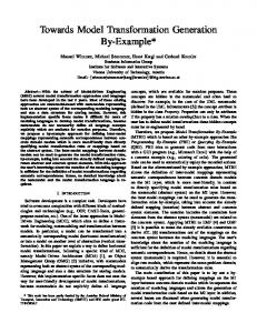
For the Tiger editor generator, a VL alphabet has to contain not only the definition of the VL’s abstract syntax, but also a specification of the intended layout which controls the generation of the visual editor. Hence, the abstract nodes, edges and attributes of an abstract syntax type graph are enhanced by concrete nodes, edges and attributes defining the shape and connection figures for the concrete layout of the abstract object. Fig. 1 shows (a part of) the Tiger meta type graph that all VL alphabet type graphs have to be typed over. At the abstract syntax level (the upper part of Fig. 1), each VL alphabet consists of NodeSymbolTypes (e.g. activities in activity diagrams), EdgeSym3
¨nsgen Ehrig, Ermel, Ha
bolTypes (e.g. next-relations in activity diagrams) and LinkTypes (the connection of EdgeSymbolTypes to NodeSymbolTypes). Moreover, NodeSymbolTypes may be attributed by AttributeTypes (e.g. names of simple activities). abstract syntax
AttributeType
layout
TextFigure concrete syntax
NodeSymbolType
layout
first
first
LinkType
begin
layout
ShapeFigure first
end
LinkLayout
EdgeSymbolType layout
Connection
second first
ConnectionConstraint
LayoutConstraint
second
Fig. 1. Meta Type Graph for VL Alphabets in Tiger
At the concrete syntax level (the lower part of Fig. 1), the graphical layout for a node symbol of a certain NodeSymbolType is given by a ShapeFigure. Up to now, the shape of NodeSymbols can be a simple form, e.g. a rectangle, circle, ellipse or a closed polygon. Shape figure properties such as stroke and fill colors are given by additional attributes (not shown in Fig. 1). The standard layout for a textual attribute of type AttributeType is given by a TextFigure (with attributes font, fontColor, ..). The graphical relations between TextFigures and ShapeFigures are expressed by LayoutConstraints, such as below(TextFigure, ShapeFigure). Figures can be connected by Connections (i.e. lines or polylines) which represent the concrete graphical layout for the EdgeSymbolTypes. The graphical representation of a link (e.g. a colored arrow head) is modeled by a LinkLayout object. Graphical relations between a Figure and a Connection can be modeled as ConnectionConstraints, such as atCenter(TextFigure, Connection). Based on a VL alphabet, Tiger uses the default Eclipse-GEF graph layout manager to compute the layout of the symbols and links in the generated editor. Editing operations modeled by abstract syntax rules are performed in Tiger-generated Eclipse editor plug-ins by AGG operating on the abstract syntax of the VL diagrams. The concrete layout is computed after each operation on the basis of the generated GEF layout features. In this sense all diagram instances edited in the generated editors, are represented at the abstract syntax level by an instance graph typed over the abstract type graph of the corresponding VL alphabet. A model transformation between diagrams typed over different VL alphabets has to relate the corresponding abstract syntax elements of both languages. 2.2
Model Transformation by Graph Transformation
In Tiger generated Eclipse editor plug-ins, the source and target languages are given by VL specifications. We describe a model transformation by graph transformation rules. The abstract syntax graph of a source model is transformed by applying transformation rules resulting in the abstract syntax graph of the target model. According to the VL specification of the target language, 4
¨nsgen Ehrig, Ermel, Ha
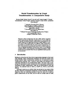
the concrete syntax for the target model is computed after the transfomation by the generated editor for the target language. A model transformation based on graph transformation is defined by an attributed graph transformation system GT S = (AT G, P ) consisting of a attributed type graph AT G and a set of transformation rules (or productions) P . The abstract syntax graphs of the source models can be specified by all (or a subset of) instance graphs over a type graph AT GS . Correspondingly, the abstract syntax graphs of the target models are specified by all (or a subset of) instance graphs over a type graph AT GT . Both type graphs AT GS and AT GT have to be subgraphs of type graph AT G (see Figure 2). The model transformation starts with instance graph AGS typed over AT GS . As AT GS is a subgraph of AT G, AGS is also typed over AT G. During the model transformation process the intermediate graphs are all typed over AT G. Please note that this type graph may contain not only AT GS and AT GT , but also additional types and relations which are needed for the transformation process. The result graph AGT is typed over AT G. If it is also typed over AT GT , it fulfills one main requirement to be syntactically correct. Data types are preserved during the transformation process. AT O GS
incT _ / AT G o ? AT : O dII O GT u II uu I u II u II uu II uu typeAGS typeAGT type u AGi II u II uu u II u II uu uu pi pj p p k l +3 3 + 3 + 3 + ... ... AGS AGT AGi incS
Fig. 2. Typing in the Model Transformation Process
2.3
Transforming Diagrams from the Source into the Target Language
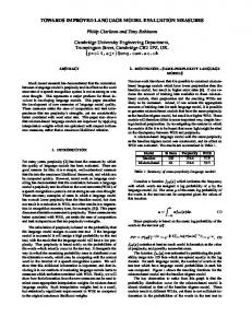
Our aim is to describe a concept for transforming diagrams of the source editor plug-in to diagrams of the target editor plug-in. We assume that the source and target editor plug-ins are generated by Tiger from source and target VL specifications. Fig. 3 shows an overview of the model transformation process. Source Graph
restrict to abstract syntax Source save Source Editor Diagram Plug−In
Model Transformation Rules
Target Target load Editor Diagram Plug−In
Fig. 3. Model Transformation Overview
5
¨nsgen Ehrig, Ermel, Ha
Starting with the source diagram we restrict the diagram to its abstract syntax and hence to the source graph in AGG. In AGG we have to provide a graph transformation system GT S = (AT G, P ) consisting of a type graph AT G which includes the abstract source and target alphabets as described above, and a set of model transformation rules P . The source diagram is imported from the Tiger editor as start graph of the existing graph transformation system in AGG. The model transformation rules transform the source graph into the target graph typed over the target language. The target graph is loaded into the target VL editor plug-in. Most information for the concrete layout is given already by the target VL specification. Yet, some model-dependent layout attributes may be missing, such as positions of diagram symbols in the editor panel. These attributes have to be set by default values or computed by a suitable layout algorithm of the target VL editor.
3
Example: From Activity Diagrams to Petri Nets
In this section we present an example for a model transformation between UML Activity Diagrams given as the source language of the generated Activity Diagram Editor and Petri Nets given as the target language of the generated Petri Net Editor. 3.1
Source and Target Languages
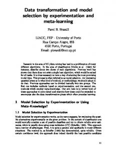
The source language alphabet for activity diagrams contains two kinds of symbol types, activities and next-relations. Activities are typed over NodeSymbolType, and next-relations are typed over EdgeSymbolType according to the meta type graph for VL alphabets in Tiger (see Fig. 1). Next-relations begin and end at activities (these begin and end relations are typed over LinkType in the meta type graph). Activities can be of different kinds, i.e. simple activities, start and end nodes as well as decision nodes. Simple activities are usually inscribed by some text. Moreover, next-relations may have inscriptions which are used to formulate conditions. The activity kind, the text and the conditions for decisions are given as attributes of the corresponding symbol types. Fig. 4 shows the sample source activity diagram for the model transformation, edited in the generated activity diagram editor plug-in. The abstract syntax graph of this diagram is typed over the type graph of the activity diagram language, shown in the left-hand side of Fig. 6. The target language alphabet for Petri nets contains NodeSymbolTypes Place and Transition for the Petri net nodes, EdgeSymbolTypes ArcPT for Petri net arcs from a place to a transition and ArcTP for arcs from a transition to a place, and LinkTypes arcPTsource, arcPTtarget, arcTPsource and arcTPtarget for linking the edge symbols to the node symbols. AttributeTypes are the names of places and transitions, their positions and the token number on a place. 6
¨nsgen Ehrig, Ermel, Ha
Fig. 4. Model Transformation Source Activity Diagram Editor Plug-In
Fig. 5 shows the target Petri net (corresponding to the activity diagram in Fig. 4), edited in the generated Petri net editor plug-in. The abstract syntax graph of this net is typed over the type graph of the Petri net language, shown in the right-hand side of Fig. 6. 3.2
Model Transformation
Petri net places model passive system parts (e.g., buffers and files), whereas transitions describe process activities. Thus, our model transformation maps activities to transitions and next-relations to places in between. The places can hold at most one token each, thus the token just shows how far the process has reached. Petri nets of this special kind are called condition-event nets. Note that decision activities are translated to two transitions, one for each possible decision branch. To each of these transitions, another place is assigned, the marking of which models the evaluation of the corresponding guard to “true”. The model transformation type graph AT G (the complete graph shown in Fig. 6) is defined by the union of the source and target language alphabets plus two reference nodes, the adjacent arcs of which connect the corresponding symbol types of both alphabets, i.e. activities to transitions and next-relations to places. Fig. 7 shows the start graph for the model transformation, i.e. the abstract syntax graph of the activity diagram in Fig. 4. The model transformation rules are defined by a graph transformation system typed over AT G. Starting with the start graph in Fig. 7, the consecutive 7
¨nsgen Ehrig, Ermel, Ha
Fig. 5. Model Transformation Target Petri Net Editor Plug-in
Fig. 6. Model Transformation Type Graph AT G
application of the model transformation rules results in the abstract syntax graph of the target diagram. Please note that the following screenshots of the model transformation rules either contain three graphs each (a negative application condition NAC, the left-hand side LHS and the right-hand side RHS of the rule), or only two graphs (LHS and RHS), if there is no NAC, or if the NAC equals the right-hand side of the rule. Fig. 8 contains all rules needed to generate places and transitions, and to build up the references between activities and transitions on the one hand, and between next relations and places on the other hand. Start and end activities are translated to places preceding and following the corresponding transition. Activities with kind=“decision-begin” are translated to two transitions. Additionally, two places are added to the pre-domain of the decision enter point 8
¨nsgen Ehrig, Ermel, Ha
Fig. 7. Model Transformation Start Graph
transitions, the marking of which model the evaluation of the guard to true. Fig. 9 shows the rules to insert arcs between transitions and places. We distinguish the handling of decision activities from others. If an activity is not a decision, a next-relation beginning at this activity is translated to a place in the post-domain of the transition corresponding to the activity by rule createArcTP. Analogously, using rule createArcPT, a next-relation ending at an activity is translated to a place in the pre-domain of the corresponding transition. Both rules have the attribute condition kind6=decide-begin and kind6=decide-end. Fig. 10 depicts the rules which handle the insertion of arcs between places and transitions corresponding to decision activities. Rule decide-begin deals with the branching structure at the beginning of a decision (the decision enter point), and rule decide-end deals with the merging structure at the end of a decision (the decision exit point). The transition names of the two transitions corresponding to the decision enter point, which are initially set to empty, are now overwritten by the guard, i.e. the inscription of the corresponding next relations. Negative application conditions (NACs) are equal to the right hand side (RHS) of the rules in Fig. 9 and 10. Rule “decide-begin” has an additional “NAC2” with the attribute condition j = i which ensures that the transition is only be connected once. Four further rules (not depicted) are necessary to delete all source and reference items, resulting in a target graph typed over the target language. The model transformation rules are structured in three different layers for controlled rule application. Starting with layer = 0, rules of the current layer are applied as long as possible. After termination of all rules in the current layer the transformation continues with the next layer (layer = layer + 1). The rules in Fig. 8 for the creation of places and transitions are assigned to 9
¨nsgen Ehrig, Ermel, Ha
Fig. 8. Model Transformation Rules Inserting Places and Transitions
Fig. 9. Model Transformation Rules Inserting Arcs (NAC=RHS)
10
¨nsgen Ehrig, Ermel, Ha
Fig. 10. Model Transformation Rules for Decisions (NAC=RHS)
layer 0. Rules inserting arcs between places and transitions (depicted in Fig. 9) have the layer number 1, and rules transforming a decision (Fig. 10) get the layer number 2. The deletion rules have to be applied at last, and thus belong to layer 3. 3.3
Consistency Analysis
The model transformation example fulfills the termination criteria for layered graph transformation systems shown in [2]. In addition, critical pair analysis was done for the model transformation example with the AGG system [14]. Although critical pair analysis could not been fully completed due to performance reasons, no critical pairs were found up to now. According to the theory in [5] the model transformation is locally confluent if there are no critical pairs left. Together with termination of the model transformation this would imply that the model transformation is also confluent and has functional behavior.
4
Conclusion
In this paper we have shown how to extend the Tiger generator of EclipseGEF based editor plug-ins in order to support model transformation from a diagram of the source editor plug-in into a diagram of the target editor plug-in. In general we benefit from the design of the generated editor plug-ins where the abstract syntax of each edited diagram is represented as a graph in AGG [14]. Such an underlying syntax graph of the source language is transformed using model transformation rules in AGG into an abstract syntax graph typed over the target language. In AGG, all available consistency checks can be applied to the model transformation rules like critical pair analysis and ter11
¨nsgen Ehrig, Ermel, Ha
mination checking. The resulting abstract syntax graph of the target language is extended by the target editor plug-in by the corresponding concrete syntax, because most of the necessary layout informations given by the target VL specification is already hard-coded in the editor plug-in Java code. Only default values for the concrete layout positions of the symbols in the target editor plug-in have to be provided by a layout algorithm. In our example, a layout algorithm for Petri nets might be given by a default graph layouter manager. As abstract syntax graphs during model transformation tend to be quite complex and may contain a large number of nodes and edges, it is difficult to check the correctness of the model transformation rules using the resulting abstract target graph in AGG. Here, the visualization of the target graph in a suitable concrete layout in the generated Tiger editor plug-in has proven to be very helpful for the validation of the model transformation rules. It remains to analyze more complex case studies for model transformation in Tiger, to get results about the scalability of our approach concerning the performance, the efficiency and the expressive power, and to compare the results to related tool-based model transformation approaches. Future work is also planned to extend the Tiger environment not only for model transformation but also to support simulation of behavioral diagrams based on graph transformation in generated simulation environments. A model transformation can be very useful for validation of a source model by simulation if a simulator for diagrams of the target language has already been generated.
References [1] R. Bardohl, G. Taentzer, M. Minas, and A. Sch¨ urr. Application of Graph Transformation to Visual Languages. In H. Ehrig, G. Engels, H.-J. Kreowski, and G. Rozenberg, editors, Handbook of Graph Grammars and Computing by Graph Transformation, Volume 2: Applications, Languages and Tools. World Scientific, 1999. [2] H. Ehrig, K. Ehrig, J. de Lara, G. Taentzer, D. Varr´o, and S. Varr´oGyapay. Termination criteria for model transformation. In M. Wermelinger and T. Margaria-Steffen, editors, Proc. Fundamental Approaches to Software Engineering (FASE), LNCS 2984, pages 214–228. Springer, 2005. [3] K. Ehrig, C. Ermel, S. H¨ansgen, and G. Taentzer. Towards Graph Transformation based Generation of Visual Editors using Eclipse. In M. Minas, editor, Visual Languages and Formal Methods, volume 127 of Electronic Notes in Theoretical Computer Science, pages 127–143. Elsevier, 2004. [4] K. Ehrig, C. Ermel, S. H¨ansgen, and G. Taentzer. Generation of visual editors as eclipse plug-ins. In Proc. 20th IEEE/ACM International Conference on Automated Software Engineering, Long Beach, California, USA, 2005. to appear.
12
¨nsgen Ehrig, Ermel, Ha
[5] H. Ehrig, K. Ehrig, U. Prange, and G. Taentzer. Fundamentals of Algebraic Graph Transformation. EATCS Monographs in TCS, Springer to appear, 2005. [6] H. Ehrig, U. Prange, and G. Taentzer. Fundamental theory for typed attributed graph transformation. In F. Parisi-Presicce, P. Bottoni, and G. Engels, editors, Proc. 2nd Int. Conference on Graph Transformation (ICGT’04), Rome, Italy. LNCS 3256. Springer, 2004. [7] Eclipse Consortium. Eclipse Graphical Editing Framework (GEF) – Version 2.1.3, 2004. http://www.eclipse.org/gef. [8] R. Heckel, J. K¨ uster, and G. Taentzer. Confluence of Typed Attributed Graph Transformation with Constraints. In A. Corradini, H. Ehrig, H.-J. Kreowski, and Rozenberg. G., editors, Proc. of 1st Int. Conference on Graph Transformation. LNCS 2505. Springer, 2002. [9] R. Heckel, J. K¨ uster, and G. Taentzer. Towards Automatic Translation of UML Models into Semantic Domains . In H.-J. Kreowski, editor, Proc. of APPLIGRAPH Workshop on Applied Graph Transformation (AGT 2002), pages 11 – 22, 2002. [10] Sun Microsystems. Java – Version 1.5, 2004. http://java.sun.com. [11] , J. de Lara, and H. Vangheluwe. Computer Aided Multi-Paradigm Modelling to Process Petri-Nets and Statecharts. In Proc. 1st Int. Conf. on Graph Transformation (ICGT 2002), LNCS 2505, pages 239 – 253. Springer, 2002. [12] Object Management Group. Meta-Object Facility (MOF), Version 1.4, 2005. http://www.omg.org/technology/documents/formal/mof.htm. [13] Object Management Group. UML 2.0 OCL Specification, 2003. http://www. omg.org/docs/ptc/03-10-14.pdf. [14] G. Taentzer. AGG: A Graph Transformation Environment for Modeling and Validation of Software. In J. Pfaltz, M. Nagl, and B. Boehlen, editors, Application of Graph Transformations with Industrial Relevance (AGTIVE’03), LNCS 3062, pages 446 – 456. Springer, 2004. [15] Tiger Project, Technische Universit¨ at Berlin, 2005. http://www.tfs.cs. tu-berlin.de/~tigerprj. [16] Varr´o D., Varr´o G. and Pataricza A. Designing the Automatic Transformation of Visual Languages. Journal Science of Computer Programming, Vol. 44(2), pages 205–227. Elsevier, 2002.