Dec 1, 2011 - high end devices, such as iPhone 4 and Palm Pre. ... We call these rendering elements the object impostors. ..... Warped and Merged.
Towards Peer-Assisted Rendering in Networked Virtual Environments
∗
Minhui Zhu
Sebastien Mondet
Géraldine Morin
National University of Singapore
University of Oslo
University of Toulouse
Wei Tsang Ooi
Wei Cheng
National University of Singapore
Manovega Pte. Ltd.
ABSTRACT This paper introduces a new technique, called peer-assisted rendering, that aims to enable interactive navigation in a 3D networked virtual environment using a resource-constrained device, by speeding up the rendering. A resource-constrained client requests part of the rendered scenes from other peers with similar viewpoints within the virtual environment, and merges the rendered parts into its own view. This approach is more scalable than previous solutions based on server-based pre-rendering. The goal of this paper is to make a strong case for the feasibility of peer-assisted rendering through the following two messages. First, by analyzing a large number of user traces from a popular virtual world called Second Life, we show that there are surprisingly many users with similar viewpoints and encompass large number of common objects in their viewing areas, indicating that a client can potentially find multiple other peers that can assist in rendering. Second, by combining three different rendering methods, each contributing to rendering of different classes of objects in the scene, we show that it is possible for a client to render the scene efficiently with little visual artifacts.
Categories and Subject Descriptors I.3.2 [Graphics Systems]: Distributed/network graphics
General Terms Performance, Measurement, Design
Keywords Peer-Assisted Rendering, Image-based Rendering, Networked Virtual Environments, Resource-constrained Devices
1.
INTRODUCTION
Networked virtual environments (NVEs) are becoming an important class of distributed multimedia applications and are getting ∗ Area
chair: Xian-Sheng Hua
Permission to make digital or hard copies of all or part of this work for personal or classroom use is granted without fee provided that copies are not made or distributed for profit or commercial advantage and that copies bear this notice and the full citation on the first page. To copy otherwise, to republish, to post on servers or to redistribute to lists, requires prior specific permission and/or a fee. MM’11, November 28–December 1, 2011, Scottsdale, Arizona, USA. Copyright 2011 ACM 978-1-4503-0616-4/11/11 ...$10.00.
increasing attention commercially, with applications such as online education, teleconferencing, and entertainment. For example, Second Life, a user-generated NVE built by Linden Lab, reports more than 21 million accounts registered and about 55,000 concurrent users as of April 2011. On the other hand, as Internet access via hand-held devices becomes prevalent, there is an increasing demand from users to access NVE interactively with these devices. Hardware manufacturers have been enhancing mobile device’s performance and capabilities, with 3G and IEEE 802.11 chips, better computational capabilities, and higher screen resolutions, enabling rich multimedia applications. Some devices are even equipped with GPUs (Graphical Processing Units), improving the audio-visual experience. These GPUs, however, are still limited in their processing capability. For instance, NVidia’s GoForce 5300 does not contain any 3D engine1 , but instead is designed to decode a large amount of multimedia formats. Powerful GPUs, such as PowerVR SGX graphics processor, which can support between 7–28 MPoly/s, are only available on high end devices, such as iPhone 4 and Palm Pre. These GPUs, however, increase the power consumption of the devices dramatically [20]. Hence, despite an increase in the networking capability, rendering high quality and realistic 3D scenes on mobile devices remains a bottleneck for mobile access to NVE. A common approach to enable mobile access to NVE is to reduce the rendering workload at the mobile client, by migrating the rendering tasks elsewhere. We say that the mobile client is assisted by an assistant that renders on behalf of the mobile client, and we call the mobile client the assistee. A large class of previous work on mobile access to NVE can be classified under the server-assisted rendering approach. A server acts as the assistant and continuously renders the 3D scene according to the assistee’s viewpoint (defined by a set of synthetic camera parameters). The resulting rendered images are encoded as a video stream and transmitted to the assistee for decoding and display. There are two main issues with server-assisted rendering. First, the approach is not scalable. 3D rendering and video encoding are computationally expensive operations. Sterkin [26] reported that a high-end server can support only 14 simultaneous assistees using this approach. One can expand the server capacity to support more assistees. For instance, Shi et al. proposed moving 3D rendering and video encoding into a cloud [25]. While such cloud-based solution provides the convenience and flexibility of instantiating a rendering server as needed, the rendering cost still increases linearly with the number of clients. Second, server-assisted rendering introduces additional latency. NVE is a highly interactive application. With server-assisted ren1 http://en.wikipedia.org/wiki/GoForce
dering, however, its takes at least one round-trip time for the new viewpoint to be rendered at the assistee. Bao and Gourlay have proposed a method to reduce the interaction latency, by warping the rendered images received from the server immediately at the assistee when viewpoint changes [1]. Despite introducing some visual artifacts due to warping, this approach works well generally. It is limited, however, to a static, single user, virtual world (such as building walk-through). In a dynamic scene (e.g., with multiple moving avatars), the warp image would not have included the updated avatars, causing these avatars to appear frozen as the viewpoint changes.
1.1
Peer-Assisted Rendering
These drawbacks of the existing proposals motivate the need for a scalable method to support rendering of dynamic scenes from a complex multi-user virtual environments on a mobile device. This paper introduces a new technique to reduce the rendering workload of an assistee, by distributing the rendering tasks to other clients, or peers, in the same virtual world. We call this approach peer-assisted rendering. Clients accessing the virtual world are heterogeneous in nature. Some clients are running on hosts with good rendering capabilities (most desktops are equipped with GPU). These clients can act as assistants, render parts of the scene separately, and send them to the assistee. We call the partial scene rendered at the assistants rendering elements. The assistee then merges the rendering elements to create its view of the scene. A fundamental question that peer-assisted rendering approach needs to address is how to split the rendering tasks and what is a rendering element. In our design, we choose to have three types of rendering elements, to balance between the rendering load on the assistee and the assistants, to maintain interactivity, and to minimize visual artifacts. The first type of rendering elements consists in the furthest objects, the sky, and the ground. These objects are rendered as one single depth-enabled image by the assistants according to their own viewpoint. We call this image the background impostor. Since the assistants are rendering them for their own use in any case, rendering the background impostor does not incur much additional overhead. The second type of rendering elements consists in the static near objects. These objects are rendered as individual images by the assistants. We call these rendering elements the object impostors. The objects are also rendered according to the viewpoint of the assistants, so it incurs very little additional overhead for them. Moreover, the assistants may already use some of these rendering elements for themselves (e.g. for rendering shadows, and reflections). The impostors and the corresponding depth maps are sent to the assistee, which warps them to its view point. The final type of rendering elements consists of dynamic objects, such as other avatars. These objects are rendered locally by the assistee as “normal” 3D objects. We now explain how to generate a new rendered image when the assistee changes its viewpoint. When the viewpoint of the avatar changes, the background impostors are warped using McMillan and Bishop’s Image Warping Algorithm [19] and are composed into the assistee’s background. Since the background impostors consists of far objects, it changes very little as the viewpoint changes. Warping the background impostors therefore does not incur much visual artifacts. If background and near objects are warped from the same image, however, exposure gaps often appear (holes in background). These near objects are therefore rendered separately to reduce the exposure gaps when the viewpoint changes (the occluded parts would be rendered by the assistants anyway, c.f. Section 3.1).
Finally, in order to maintain interactivity with other avatars, the assistee renders all other close/dynamic objects itself. This way, their updates or movements are reflected with minimal delay and maximal quality at the assistee. The strengths of peer-assisted rendering are the following. First, it is more scalable than a server-assisted approach. It uses the rendering capability of other clients of the environment to partially render the scene on behalf of the assistee. Second, it reuses rendered elements from the assistants. The rendering elements from the assistants are rendered according to their own viewpoint – and it is something that they already do anyway. Third, it can adapt to the rendering capability of the assistee. By tuning the classification of objects into rendering elements, we can trade off visual artifacts with the rendering workload at the assistee. Finally, by rendering the moving avatars locally at the assistee, peer-assisted rendering maintains the interactivity between the user and the virtual environment.
1.2
Contributions
There are many hurdles and research challenges in realizing peerassisted rendering practically. In fact, too many to be addressed in a single paper. This paper, as the first paper introducing this concept, aims to establish a solid case for the efficacy of peer-assisted rendering. We choose to address two fundamental questions in this paper: (i) are there enough assistants with similar viewpoints and common objects to help an assistee? (ii) what is the quality of the scene rendered at the assistee as user navigates around the scene? To answer the first question, we analyze mobility and object traces from a popular NVE named Second Life. We show that there are surprisingly many avatars with significant overlaps in viewing frustum, and most assistees can find enough assistants to cover a large number of objects in their viewing frustum. To answer the second question, we build a renderer that simulates the peer-assisted rendering process, and show that the resulting rendered quality is close to that if rendered fully by the assistee.
1.3
Organization
The rest of this paper is organized as follows. Section 2 presents relevant past research efforts. Section 3 describes how the rendering is done. Section 4 defines two similarity metrics and describes how assistants are chosen. Section 5 shows the setup and the results of our experiments. Section 6 presents the results of the Second Life trace analysis. Finally, Section 7 discusses the challenges for future work. we conclude in Section 8.
2.
RELATED WORK
Navigating through, and interacting with, a large NVE on a mobile phone with limited computational capacity is challenging. The computational demand to render the 3D scene in NVE leads to low rendering frame rate. A common technique to improve the frame rate is to reduce the details of 3D content within the NVE. Previous work has proposed to simplify the geometry of 3D models [10] or filter out objects (by making them invisible) on the mobile client [17]. Despite improving the frame rate, these techniques reduce the quality of the rendered scene. To maintain high level-of-details in the scene and high frame rate at the same time, server-based rendering schemes, was proposed [7, 21]. With this approach, the client continuously sends its viewpoint to the server. The server renders the 3D scene according to the client’s viewpoints as a sequence of images, and transmits the resulting sequence to the client for display as a video stream. To reduce the bandwidth consumed by transmissions of the rendered scene to the clients, warping-based techniques have been pro-
posed. The idea is that the server transmits only selected rendered scenes, along with the depth maps of each scene. These rendered scenes are accurately rendered by the server. The clients interpolates between the rendered scene, by warping the given images to target viewpoint [5, 2]. Chang and Ger [5] proposed that the server creates a layered depth image of the scene corresponding to the mobile client’s viewpoint. The layered image is then transmitted to the client for warping; layered image gives good result even with exposure gaps. Bao and Gourlay [2] propose that the clients generate subsequent frames locally using 3D warping upon receiving the rendered scene. Differences between the rendered images and the warped images for the next viewpoint are requested from the server. Shi et al. [23] use warping for mobile clients in a slightly different context: in their setting, the input data is a 3D video stream. A dedicated proxy transforms the 3D video into well-chosen 2D frames and depth maps to be sent to the mobile client. These proxies may distribute the computational problem among various independent machines, and move the rendering process closer to the client, which improves interactivity. The availability of such powerful proxies, however, is not realistic for Internet-based NVE applications. The latency of the latter setup has been then improved by warping from multiple images. To get reference images well suited for warping, a viewpoint prediction algorithm is used [24]. Prediction/prefetching algorithms for server-side image-based prerendering are also studied by Lazem et al. [12]. Another approach is based on pre-rendered panoramic images. In Boukerche and Pazzi’s system [3], the server receives the mobile user’s viewpoint and warps from a panoramic view in cylindrical coordinates for the client. Lei et al. [13] suggested that the client warps the scene himself from a portion of the panorama. In both works, a buffering method is proposed for anticipating the prerendering. Chen et al. [6] propose an on demand image-based networked visualization method. The client can pull pre-rendered multi-resolution images from a web-server. The proposed approaches above are not scalable. The server (or proxy) either has to render 3D scenes along with real-time video encoding for each client according to its successive viewpoints, or has to pre-render a large database of possible scenes (like panoramic or movie) to cover the 3D environment. These server operations are computationally expensive. Hence, an increasing number of clients may quickly exhaust the server’s capabilities. To allow more mobile users to connect simultaneously, Lamberti et al. [11] use a cluster-based rendering farm based on Chromium2 OpenGL implementation. To reduce the computing load of the server, some of the work mentioned [6, 3, 13] propose to buffer some pre-rendered scenes. Caching may lead to synchronization issues in large scale NVEs, such as Second Life, where the rendered scenes are dynamic. Even for the static part of the scenes, it would require the pre-rendering, and the storage, of huge amounts of images, consuming computing resources. Boukerche et al. [4] improve their previous system [3] from a scalability point of view. The authors use peer-to-peer distribution to share the images rendered by the server. A peer can find other peers that visit the same “region of interest” and ask them for images. The spirit of their work is similar to ours, but using only a single image, the technique works best for static scenes. Most other pieces of work related to P2P techniques in NVEs have stressed on performing load-balancing for the network and/or server re2 http://chromium.sourceforge.net/
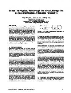
Figure 1: The frustum-related vocabulary.
sources. One example of P2P optimization for NVEs is Ke and Zimmermann’s [15] spatialised audio streaming system. They aim at improving the delivery of audio streams while minimizing the latency using a P2P bandwidth balancing model. Regarding the actual 3D objects, Cheng et al. [8] investigate the streaming of progressive meshes within a P2P NVE. They partition the meshes into chunks and show how a node can lookup for the provider of a given chunk. Within the ASCEND project3 , Hu et al. [9] considers improvements on P2P techniques for sharing 3D content. Their focus, however, is to share geometric data of the scene and does not concern rendering.
3.
ASSISTEE RENDERING
We now elaborate on how the assistee utilizes different rendering elements from the assistants to produce the rendered scene. We first briefly review the classical rendering pipeline and introduce some notations. Then, we detail the concept of warping from a single image introduced by McMillan and Bishop [19]. The next subsection explains the partitioning of the scene and defines the notion of an impostor, as we use it here. Finally, we show the composition of the different rendering elements and evaluate the quality and efficiency of the assisted rendering.
3.1
3D Rendering
To establish a common vocabulary for the rest of the paper, we now briefly explain how 3D rendering is typically done. Rendering is the process of automatically generating a 2D image from a set of virtual 3D objects. The set of objects potentially visible from a given viewpoint is delimited by a volume called the frustum; Figure 1 provides details about the vocabulary related to the viewpoint. As most users in an NVE have horizontal view directions, our study in Section 4 uses simplified parameters for the viewpoint definitions: we consider the position of the user (“eye-point”), his view direction, and his viewing angle (“horizontal field of view”). In most NVE applications, the process is implemented in three steps. The first step, perspective transformation, uses a geometric function to transform all 3D objects contained in the frustum. Its complexity 3 http://ascend.sourceforge.net/
is linear in the numbers of 3D geometric primitives within the frustum. The next step, projection to the 2D screen plane, removes the depth coordinate. Finally, the rasterisation step converts the continuous image on the screen plane into a pixel array in the rendered image. The depth value is kept for each pixel, and used to manage per-pixel occlusions (with the Z-Buffer algorithm). This per-pixel depth information can be stored as the depth map of the image and may be used for 3D image warping (c.f. 3.2). Note that all objects within the frustum are processed through the rendering pipeline, since occlusions are treated by the last step –Z-Buffer– of the pipeline. Any object within the frustum of an assistant, even if occluded, is rendered and may be re-used by the assistee for warping. Moreover, note that the overall complexity of the rendering is a linear function of the number of triangles, or polygons, in the scene for the first two parts (perspective transformation and projection), and linear in the number of pixels for the rasterization. Of course, GPUs do implement these operations in parallel on geometric elements for the first two parts, and on pixels for the rasterization.
3.2
Assistee
Warped and Merged Background
Warped Object Imposters
Single Image Warping
We now briefly explain 3D image warping. In the context of peer-assisted rendering, image warping is used to generate a view from the camera of the assistee when viewpoint changes, taking advantage of the depth information kept by standard rendering engines (e.g. OpenGL-based). Exact warping can be done for certain camera moves: homographies are exact for rotations around the “eye-point”, or also, for arbitrary motion of a planar object. The image rendered from a given viewpoint A, associated with its depth map, contains enough information to re-render (or warp) adequately all the pixels visible by A from a different viewpoint B. The correctness of the rendering is up to the quantization of the image information due to the rasterization step and of the depth due to its storage in the depth map. Pixels visible from B but not from A, however, will not be present in the warped image; this creates well known artifacts called exposure gaps. Exposure gaps may be thwarted by merging multiple reference images [23]. Mark et al. [18] present a concise review on these methods and provide a more elaborated transformation, which depends on more information from the rendering process. Pixels visible from B that are occluded in A may be hidden by a different object, or by self occlusion. Self occlusion occurs when the angle between the two view points is more than the change of normal in the silhouette edge of the object. Although it is hard to quantify, the number of occlusion due to a different object seem to be higher than the number of self occlusion in NVE that have a complex scene with many objects. Therefore, we propose to warp objects of the scene independently, to reduce the number of exposure gaps caused by object occlusions. In terms of complexity, 3D image warping is fast since it is linear in the number of pixels of the image being warped.
3.3
Assistant 2 Assistant 1
Decomposition of the scene
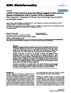
With the background on 3D rendering and 3D image warping, we can now elaborate on how the assistee renders its scene. The assistee partitions the scene into three classes of rendering elements: background objects, near static objects, and dynamic objects. These rendering elements can be rendered by different assistants, warped independently, before being combined by the assistee (Figure 2). Such partitioning has two main advantages. First, warping static nearby objects independently from the background significantly reduces the number and size of exposure gaps. To understand this, consider the alternative where the assistant renders the near objects
Self-Rendered Objects
Assistant 2 Assistant 1
Assistee
Figure 2: In the upper figure, an assistee may recover the three (green) objects in his frustum –not drawn entirely for clarity– from two neighboring peers. Both assistant provide the background. In the lower figure, the assistee has warped the three impostors, warped and combined the two backgrounds, and rendered locally only the dynamic objects –here the two red little guys– and merged these rendering objects together.
together with the background objects as one impostor. The pixels corresponding to the background region occluded by the near objects would not be available when the image is warped, creating an exposure gap. Rendering the background objects and near objects as separate images eliminates such exposure gaps. In a way, we are rendering images with multiple layers, similar to the idea behind layered depth images [22]. Second, by partitioning the scene into different rendering elements, the rendering workload can be distributed to more than one assistants, leading to a more flexible and scalable solution. Different assistants may be chosen. The choice of the assistant is discussed in Section 4. Here is how the partitioning is done. First, objects that are of distance d and above from the eye-point of the assistee are grouped together to form the background objects (we use half of the far plane distance as d in our work). We also force the ground to be in the background so that it does not suffer from exposure gaps. Second, static objects that are within distance d from the eye-point of the assistee are grouped into impostors. Grouping is done using scene graph – a tree that organizes objects in the scene into a hierarchy based on spatial position of the objects. An impostor is a rendered image of a group of objects that corresponds to a subtree in the scene graph. We can adjust how fine we want to partition the scene by moving up and down the scene graph. In our examples, we have between 20 and 120 impostors. Finally, dynamic objects such as avatars that are within distance d from the eye-point of the assistee form the third partition. These objects are rendered as 3D objects locally.
3.4
Hybrid Rendering
View of The Assistant 1
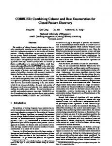
To generate the rendered scene, the assistee combines the three classes of rendering elements, two of which are warped, and one is rendered regularly. The assistee, upon encountering a new object in its frustum or upon experiencing large visual artifacts in rendering of an object, sends a request to an assistant based on the assistant selection algorithm (see Section 4) for the corresponding impostor. The assistant renders the requested objects as an impostor and sends them, together with the corresponding depth map, to the assistee. The same is done for the background impostor. This hybrid rendering is illustrated by Figure 2. Instead of making the assistants generate the impostors according to the assistee’s viewpoint, we choose to use warping at the assistee. The assistee knows the viewpoint of the assistant from which the impostors come from, and uses this information to warp them to its own viewpoint. This approach improves the overall latency for two reasons. First, the assistant does not need to get updates of the assistee’s viewpoint, which would increase the network round-trips. Second, by reusing the assistants’ depth-enabled images, the assistee can move in the scene and continue warping without requiring any additional information. The scene at the assistee now consists of a warped background, warped impostors and moving objects within distance d from the eye-point (including the avatars). The assistee now renders the scene using regular graphics pipeline. The composition of the three types of rendering objects is also performed by the last step (Zbuffer) of the graphics pipeline, using the depth information of the 3D objects of the background and of the impostors. Figure 3 shows an example that illustrates the whole process and a ground truth rendered image for comparison.
3.5
4.
Warped backgrounds
Warped objects
Merged background
Merged View (with error concealment)
Rendered view (assistee's result)
Computational Complexity
The complexity of the classical rendering process depends on both the number of polygons in the scene and the number of pixels in the screen (Section 3.1). the complexity of a warping pass, however, depends only on the number of pixels of the warped image. Thus, the traditional 3D graphics pipeline does not benefit much from the smaller display size of a mobile device, whereas warping does [19]. The complexity of warping is comparable to the complexity of the rasterization step of 3D rendering. Hence, when warping an object, the time spent in the perspective transformation step and the projection step is saved, compared to 3D rendering. Moreover, grouping the objects simplifies warping further: in 3D rendering, objects are rasterized independently, whereas objects being warped together lead to a single pass on the pixel array. In particular, warping the background objects into a single image avoids considering the objects that are far away one-by-one. Note the resolution of the grouping (how many objects per impostors) may be chosen: more object per impostors leads to less impostors, which lowers the complexity of the rendering at the expense of more visual artifacts (exposure gaps).
ASSISTANCE
The goal of this study is to prove the concept for peer-assisted rendering. We consider the scheme where a mobile device profits from rendering work already done, and cached, by other peers. The assistee will have to build its view of the scene by using image warping from the rendering results (object images) from other viewpoints (c.f. Section 3). Therefore, the assistee needs to find other peers that can provide him with, at least, partial rendering results corresponding to his viewpoint, i.e., other peers that see a part of what he sees. In order to show that this peer-assisted scheme is viable in the current usage of Second Life, we need to define
View of The Assistant 2
Self-rendered 3D Object
Target view (ground truth)
Figure 3: An example of hybrid rendering at the assistee: Assistant 1 provides the impostors and a part of the background, Assistant 2 provides a complementary part of the background, and the dynamic object (the avatar) is rendered locally.
notions of similarity for avatar views. In the remaining of this section, we build two similarity criteria which reflect how much the assistant may help with object images or for background warping.
4.1
Quantifying View Similarity
We define similarity metrics as a measure between the assistee and a set of candidate assistants. These metrics measure the capacity of a set of potential assistants in providing the objects impostors and background to the assistee. We define two similarity measures, object similarity and viewpoint similarity, below. We first define the notion of object similarity between an assistant and an assistee. This similarity measure counts the ratio of the number of objects that falls into the viewing frustum of both the assistant and the assistee, to the number of objects in the viewing frustum of the assistee. The idea here is that, if an object falls into the frustum of the assistee, it is needed by the assistee, and if it also falls into the viewing frustum of the assistant, then it can be rendered as an impostors by the assistant. There is an additional factor to consider, however. The impostor would not be helpful to the assistee if the difference in the viewing
Figure 4: Pairs of 2D viewpoints and their overlapping area ratios. Viewpoint similariry is computed by filtering with the angle between viewing directions.
angle of the assistant and assistee to the object is large. Warping of the impostor in this case would generate large visual artifacts. In the worst case, the assistant and assistee could be facing each other with the object in between. In this case, the impostor from the assistant would be useless. As such, we filter out assistants whose differences in viewing angle with respect to the assistee’s viewing angle is larger than a threshold, and set the similarity to zero. This metric naturally generalizes to more than one candidate assistant, by considering the number of object shared between the assistee and any of the candidate assistants, thus taking into account the complementarity of the assistants. The object similarity is indicative of the amount of data that can be shared between the assistant and the assistee, but it involves point in polygon query, which could be expensive, especially on the assistee that is already resource-constraint. We introduce another similarity measure that is easier to calculate and approximate the object similarity, called viewpoint similarity. Viewpoint similarity computes the area of the intersection between the view frustum of the assistant and the assistee. To compute viewpoint similarity, we only consider 2D view frustum in the xy-plane. We ignore the z-angle, the angle between the vector z_camera and the horizontal plane (c.f. Figure 1), since most users have a horizontal viewing direction. We also ignore the near-plane. Hence, the 2D viewpoint of a peer is modeled by a triangle: the position is the vertex, facing the edge projection of the far-plane, and the two remaining edges are defined by the sides of the 3D frustum (see Figure 4). Two viewpoints are then compared using the overlapping area between two 2D viewpoints, that is, the projection of the “intersection volume” on the horizontal plane (c.f. Figure 1). We compute the similarity as the ratio between the overlapping area and the area of the assistee. The similarity for a pair of avatars thus ranges between 0 and 1, with 1 representing the same viewpoint (c.f. Figure 4). As in object similarity, we set the similarity between two avatars to zero when the angle between their view directions is larger than a threshold (we use the default horizontal FOV setting in Second Life, which is 91 degree). To extend this metric to multiple assistants, we compute the intersection between the assistee’s 2D viewpoint and the union of all assistants’ 2D viewpoints whose viewing angle lies within the threshold. In Section 6, we show that the viewpoint similarity is very close to object similarity, thus, we use only viewpoint similarity to select the assistants, as explained in the next section.
4.2
Selecting Assistants
We now formally define how an assistee can determine which assistant(s) to use, using viewpoint similarity as the metric. Let a be the assistee, and A be the set of candidate assistants in the system, whose difference in viewing angle with respect to the
Figure 5: Position and Viewing Direction of Assistants.
viewing angle of the assistee is below the given threshold. Define V S(a, S ), where S ⊆ A is a subset of A , as the viewpoint similarity between the assistee a and the assistants in S . The assistant selection problem can be defined as follows: Given a and A , find
Smax = arg max V S(a, S ) S ⊆A
A naive approach would involve enumerating all the possible subsets of A , which takes exponential time. Instead, we choose to use a O(kn) greedy algorithm to approximate S , where k is the number of assistants chosen, and n is the size of A . The algorithm works as follows. First, the assistee sets S to empty. It then picks the assistant such that the addition of this assistant to the set S would increase the value of V S(a, S ) the most. It repeats either until we have k assistants in S , until the value of V S(a, S ) is larger than V Sth , or until S does not increase after increasing k by one. The next section shows the efficiency of the proposed selection for finding good assistants.
5. 5.1
RESULTS Experimental Setup
We now present the rendering results from a scene in Second Life using peer-assisted rendering, with assistants selected using our greedy algorithm. Our goal here is to establish the efficacy of peer-assisted rendering through a simple, illustrative experiment. We modified the Second Life client to include a user interface to position assistants in a Second Life region. This modification allows our experiment to be reproducible. We changed the rendering pipeline of Second Life so that it is capable of partially render a scene as background and object impostors. In our experiments, we placed 10 assistants into a region named Mauve in Second Life. The impostors rendered by these assistants are stored and used in our assistee simulator. The location and viewing direction of the assistants are shown in the map in Figure 5. The assistee simulator is a rendering client that we developed. This simulator simulates peer-assisted rendering by receiving, as input, the positions, the viewing parameters, and the impostors rendered by the assistants. The simulator then renders the scene in real-time. User can navigate in the virtual environment by interacting through the keyboard. For each frame, the simulator runs the assistant selection algorithm, and picks the best assistants out of the 10 candidates. Once the best assistants are chosen, the simulator renders the scene by warping the impostors, composting the warped impostors, concealing the errors in the resulting frame, mixing in the 3D objects, and finally displaying the result.
Figure 6: Rendering results with different number of assistants and the ground truth. From Left to Right: one assistant, three assistants, five assistants, ground truth.
Figure 7: Rendering results with different viewpoint similarities and the ground truth. From Left to Right: 0.6, 0.8, 1.0, ground truth.
5.2
Rendering Results
We present here the rendering results at the assistee. To understand the effect of the number of assistants and to validate the viewpoint similarity criteria between the assistants and assistee, we show the rendering results when different number of assistants are chosen and when a different similarity threshold is used. Figure 6 shows the rendering results of the first frame if the assistant selection algorithm chooses 1, 3, and 5 assistants respectively. The ground truth is also shown for comparison. As expected, as the number of assistants chosen increases, the amount of visual artifacts reduces. Interestingly, with one assistant only, the majority of the impostors and a large part of the background are rendered properly already. This observation supports the usefulness of viewpoint similarity and our assistant selection algorithm. Figure 7 shows the rendering results if the assistant selection algorithm stops running when the viewpoint similarity threshold exceeds a given value (V Sth = 0.6, 0.8 and 1.0). A threshold of 1.0 means that the assistant selection algorithm stops only after it fails to find any assistant that can improve the similarity. Here, we can visually quantify the impact of viewpoint similarity, even for impostors. As viewpoint similarity increases, the amount of visual artifacts reduces. Even with a viewpoint similarity of 1.0, however, we still have visual artifacts due to warping. Three kind of visual artifacts are visible: sampling issues (e.g., on the ground), exposure gaps (corresponding to white pixels on the image), and synchronisation issues (e.g., on the TV wall). Whereas exposure gaps issues are inherent to warping (as discussed in Section 3.1), we see here that using multiple assistants reduce significantly these issues. For sampling, many papers have addressed this resolution problem in the context using splatting, meshing [18] or more sophisticated modeling like LDI trees (e.g., [22]). The error concealment using splatting is illustrated on Figure 3. In the future, we want to take advantage of our object-based implementation for solving the sampling issue. The last issue causing the mixed images on the TV screens could be solved by changing the similarity metric to favor updated assistants. We now show the result of our peer-assisted rendering on this set of 10 assistants, with k = 10 and V Sth = 1. Our assistee navigates
through the scene as a user controls its trajectory. In this sequence, we are able to get an average similarity of 0.9. The number of assistants used varies between 3 and 6 (average is 4.1) depending on the position of the assistee. Figure 8 shows the rendered results for every 20 frames. The exposure gaps appearing in the sequence are due to the quantization of the rasterization, and could be solved by a more careful (and a little more complex) warping. Note however that no exposure gap due to occlusion between objects occurs, as in the classical warp from a single image.
5.3
Communication Overhead
We now discuss the communication overhead incurred by peerassisted rendering. Using our proposed approach, the data traffic from the assistants to the assistee consists of rendering elements, which are sent only when the set of chosen assistants changes. Further, the rendering elements of background objects and static near objects can be cached and reused. Thus, when the assistee moves slowly in the NVE (e.g., walking), new rendering elements are sent infrequently and the communication overhead is kept small. Using video-based server-assisted rendering approaches [7, 21], the server continuously sends the rendered scene as a video to the assistee. Thus, the communication cost increases with time. In our experiment above, we navigate the assistee in the vicinity of the assistants for about 1.5 minutes, generating a total of 2328 frames. Compressing these frames as a high quality MPEG-4 video4 yields a 14 MB video. On the other hand, the navigation of the assistee causes all 10 assistants to eventually send their impostors and associated depth maps to the assistee. We compressed the impostors using JPEG and the depth maps using lossless fpzip [16], resulting in total data size of only 2 MB. Figure 9 shows the cumulative communication overhead over time in our experiment for the first 1000 frames. For peer-assisted rendering, the overhead is bursty – a large burst of data is sent when a new assistant is chosen. The rendering elements, however, can be cached and reused to 4 We use mencoder with variable bit rate option, average bit rate of 500 kbps, 10 frames per GOP, and no B-frames.
Figure 8: Every 40 frames of an image sequence generated by hybrid rendering: background, and nearby objects are warped, both avatars are rendered locally. The second row shows the corresponding ground truth images.
7000
Peer Assisted Rendering Video-Based Approach
Cumulative Data Transmitted(KB)
6000
5000
4000
3000
2000
1000
0 0
100
200
300
400
500 Frames
600
700
800
900
1000
Figure 9: Cumulative communication overhead.
render a new frame if no new assistant is chosen. Thus, the communication overhead remains flat most of the time.
6.
ANALYSIS OF SECOND LIFE TRACES
Having established the efficacy of distributed rendering, we now focus on answering another fundamental question. Will there be enough supply of assistants with common viewpoints or objects? To answer this question, we analyze a large collection avatar traces from Second Life to study the viewpoint similarity and object similarity between the avatars from a real, popular virtual world. The traces are collected following similar procedure as those described by Liang [14]. There are two separate groups of experiments, one to collect avatar mobility traces, and the other to collect object traces. The collection of avatar mobility traces is conducted with a customized, command-line based, Second Life client that acts as a bot. We placed this bot in the region in which we want to collect the avatar mobility traces. The bot receives state updates from the server. These updates contain the position and viewing direction of each avatar. These information are logged by the bot every 10 seconds. The collection of object traces are done by moving the bot systematically in a region. As the bot receives new objects information from the server, it logs the position the objects. We use traces from three regions in Second Life: Sunland, Japan Resort, and Freebies. We choose a one-hour period to analyze in this paper. Previous analysis of traces in Second Life have shown little hour-to-hour variability in the characteristics of the avatar mobility. Basic trace information is summarized in Table 1, showing
the number of records (each record contains information about one avatar at one time instance) and the number of unique avatars (how many unique avatars visited the region within the trace period) for the time period. We calculate the distribution of similarity between the avatars as follows. We explain the steps for viewpoint similarity, but the steps for object similarity is the same. For each region, for each time t in the trace, and for each avatar a that appears in time t in the trace, we do the following. We compute the viewpoint similarity between this avatar a and all the other avatars in the region at time t, and find the avatar with the highest viewpoint similarity with a. In other words, we find the highest viewpoint similarity over all possible pairs (a, i) where i 6= a. Let’s denote this maximum value of viewpoint similarity as V Smax (a,t). We then average V Smax (a,t) over all time t where a exists in the region during the period of analysis to obtain the average maximum viewpoint similarity V¯Smax (a) for each avatar a. We plot the CDF for V¯Smax (a) for the three regions in Figure 10. In the same figure, we also plotted the CDF for average maximum viewpoint similarity for each avatar a and two other avatars, and similarly, for three other avatars. The sets of two or three avatars are considered exhaustively since we want here to prove the existence of good potential assistants –unlike in Section 5 where a greedy strategy is preferred to limit the computation time. The results can be interpreted as follows. Take Japan Resort for example. Consider an assistee that uses k assistants. If k is 1, then on average, more than 20% of the avatars have an assistant that has viewpoint similarity of about 0.7. If two assistants are used (k = 2), then every avatar can find two assistants with combined viewpoint similarity of 0.85 or above. Following this interpretation, for all three regions that we analyzed, we can see that there is a significant amount of avatars with high viewpoint similarity, especially if we use two assistants. In all cases, more than half of the avatars can find two assistants with viewpoint similarity above 0.6. Figure 10 also indicates that, as the number of assistants chosen increases to three, the improvement in the viewpoint similarity is limited, and in some cases, even reduces. The decrease is because for some assistees only two candidate assistants are passing the filtering on viewing angle difference: the number of samples for best-2 and best-3 is thus different. The second row of Figure 10 plots the object similarity (defined in Section 4.1), calculated for a set of two or three assistants the same way as for the viewpoint similarity. We can see that half of
Region Name Freebies Japan Resort SUNLAND
Date/Time Collected 12:00, 23 January 2011 12:00, 23 January 2011 12:00, 23 January 2011
Number of Records 5786 5912 2516
Number of Unique Avatars 71 61 53
Table 1: Information on Second Life Traces Used Japan Resort 12:00:00 Average Best-N-Peers Viewpoints Similarity 1
0.8
0.7
0.7
0.5 0.4
Probability (CDF)
0.8
0.7 0.6
0.6 0.5 0.4
0.6 0.5 0.4
0.3
0.3
0.3
0.2
0.2
0.2
0.1
0.1
0.1
0 0.2
0.3
0.4
0.5
0.6 Similarity
0.7
0.8
0.9
1
0 0.2
Japan Resort 12:00:00 Average Best-N-Peers Objects Similarity 1
0.3
0.4
0.5
0.6 Similarity
0.7
0.8
0.9
1
0.3
1
0.7
0.7
0.4
Probability (CDF)
0.7 Probability (CDF)
0.8
0.5
0.6 0.5 0.4
0.3
0.2
0.2
0.1
0.1
0.1
0 0.5
0.6 Similarity
0.7
0.8
0.9
1
1
0.4
0.3
0.4
0.9
0.5
0.2
0.3
0.8
0.6
0.3
0
0.7
Best-1-Peers Sml Best-2-Peers Sml Best-3-Peers Sml
0.9
0.8
0.6
0.6 Similarity
Best-1-Peers Sml Best-2-Peers Sml Best-3-Peers Sml
0.9
0.5
Freebies 12:00:00 Average Best-N-Peers Objects Similarity 1
0.8
0.2
0.4
SUNLAND 12:00:00 Average Best-N-Peers Objects Similarity
Best-1-Peers Sml Best-2-Peers Sml Best-3-Peers Sml
0.9
Best-1-Peers Sml Best-2-Peers Sml Best-3-Peers Sml
0.9
0.8
0
Probability (CDF)
Freebies 12:00:00 Average Best-N-Peers Viewpoints Similarity 1
Best-1-Peers Sml Best-2-Peers Sml Best-3-Peers Sml
0.9
Probability (CDF)
Probability (CDF)
SUNLAND 12:00:00 Average Best-N-Peers Viewpoints Similarity 1
Best-1-Peers Sml Best-2-Peers Sml Best-3-Peers Sml
0.9
0 0
0.2
0.4
0.6 Similarity
0.8
1
0
0.1
0.2
0.3
0.4
0.5 Similarity
0.6
0.7
0.8
0.9
1
Figure 10: CDF for Viewpoint (top) and Object Similarity (bottom) for three regions: Japan Resort (left), SUNLAND (center), Freebies (right).
the assistee have an average of at least 0.5 object similarity with the best assistant, and this value improves to at least 0.7 if the assistee uses two assistants. In other words, two assistants can provide impostors for 70% of the objects half of the time. Just like viewpoint similarity, as we increase the number of assistants, the object similarity does not improve dramatically. These trace analysis shows that in a practical NVE, even when there are only tens of avatars in a region, it is feasible to find enough peers that share similar viewpoint and a common set of objects in the viewing frustum, which is one of the fundamental conditions for peer-assisted rendering to be practical. This result further supports the efficacy of the peer-assisted rendering.
7.
RESEARCH CHALLENGES
We have presented a first case for using peer assistance in rendering complex dynamic 3D scenes on mobile devices, showing clearly that there are supply of peers with similar viewpoint in a popular NVE, and a simplified rendering can yield good quality. In this section, we want to point out the coming challenges for pushing the idea of peer-assisted rendering further. Our work did not consider yet the transmission issues. Bandwidth, loss rate, and latency between the assistee to a chosen assistant can effect the interactivity and rendering quality at the assistee, and need to be considered. Thus, the overall system needs to trade off among: (C1) computational cost on the assistee, (C2) quality of the rendered scene on assistee, (C3) the quality of the assistant, (C4) the resources at the assistant, and (C5) bandwidth requirements. In this paper, we have started addressing the constraints (C1) and (C2) on the assistee. For (C1), the proposed rendering scheme based on rendering elements is already flexible since the grouping strategy can be adapted. Different rendering elements could easily be added (e.g., billboards) for objects that are
flat enough. For (C2), we have shown that the quality of the rendered images is satisfying. The frame rate, and its dependence to the rendering solution needs to be studied. In particular, we could imagine adapting the rendering to meet a minimum frame rate requirement, considering other characteristics of the assistant(s) and the network. For choosing the assistant (C3), we have proposed a metric based on geometric properties (position, frustum) of the assistant(s) relative to the assistee. These metrics extend to a set of assistants, which is important since covering the background is necessary for a complete representation of the scene. We have also shown that this geometric similarity approximates well enough the object metric proposed, and thus is usable for choosing assistant for impostors. Other characteristics of the assistant, such as availability in terms of resources (C4), could be taken into account. If the assistant has spare CPU or GPU cycles, we could then let the assistant warp for the assistee (or perform 3D rendering for the assistee). In that case, the assistee will have to send in its geometric parameters (position, frustum) and the assistant may have to download some part of the scene he is not seeing himself. Finally, the network conditions have to come into play. Synchronization issues, due to network latency, will occur and have to be measured. The network proximity (RTT) could also contribute to the metric measuring the quality of an assistant. More generally, network conditions could drive the strategy of the assistee: keep warping the background from an image received at a previous cycle if the network bandwidth is low. These criteria (C1 – C5) are often incompatible with each other. Trading off these different criteria is non-trivial and is the next step that our research will undertake. Other open issues in peer-assisted rendering include incentives and security. We have assumed that assistants are honest and altruistic. In practice, users need incentives to contribute bandwidth
and rendering capacity to help other users. One approach could be to reward the assistants with virtual money (e.g., Linden Dollars in Second Life), either from the server or from the assistee. Another interesting issue is security. Such peer-assisted scheme needs to be robust against malicious users. A malicious rendering assistant may provide the wrong scene to the assistee, making the NVE unusable to the assistee. A malicious assistee might seek assistance from other users even though it might not need it, wasting the resources of the other users (a denial of service attack). Preventing malicious assistant and assistee are interesting open issues that we plan to look into in the future.
8.
CONCLUSION
We have proposed a method for easing the access to NVE with a device with limited rendering capacities. Our approach is scalable: rendering assistance comes from other peers. It is also tunable: we can adjust the classification of the rendering elements to allow a trade-off between rendering quality and computational cost. We first show through an experimental setup that our approach provides satisfying rendering quality and a lower complexity for the assistee while keeping low overhead for the assistants. Then, by analyzing traces from Second life, we show that the density of avatars is sufficient to insure a high probability of finding an appropriate rendering assistant.
9.
REFERENCES
[1] P. Bao and D. Gourlay. A framework for remote rendering of 3-D scenes on limited mobile devices. IEEE Trans. on Multimedia, 8(2):382 – 388, April 2006. [2] P. Bao and D. Gourlay. Collaborative walkthrough using 3D warping. In Proceedings of ICCCE ’08, pages 1110–1115, Kuala Lumpur, Malaysia, 2008. [3] A. Boukerche and R. W. N. Pazzi. Remote rendering and streaming of progressive panoramas for mobile devices. In Proceedings of ACM MULTIMEDIA ’06, pages 691–694, Santa Barbara, CA, USA, 2006. [4] A. Boukerche, R. Werner, and N. Pazzi. A peer-to-peer approach for remote rendering and image streaming in walkthrough applications. In Proceedings of IEEE ICC ’07, pages 1692 –1697, june 2007. [5] C.-F. Chang and S.-H. Ger. Enhancing 3D graphics on mobile devices by image-based rendering. In Proceedings of IEEE PCM ’02, pages 1105–1111, London, UK, 2002. [6] J. Chen, I. Yoon, and W. Bethel. Interactive, internet delivery of visualization via structured prerendered multiresolution imagery. IEEE Trans. on Visualization and Computer Graphics, 14(2):302–312, 2008. [7] L. Cheng, A. Bhushan, R. Pajarola, and M. E. Zarki. Real-time 3D graphics streaming using MPEG-4. In Proc. of the IEEE/ACM Workshop on Broadband Wireless Services and Applications, 2004. [8] W. Cheng, D. Liu, and W. T. Ooi. Peer-assisted view-dependent progressive mesh streaming. In Proceedings of ACM MULTIMEDIA ’09, pages 441–450, Beijing, China, 2009. [9] S.-Y. Hu. A case for 3D streaming on peer-to-peer networks. In Proceedings of Web3D ’06, pages 57–63, Columbia, Maryland, 2006. [10] H. Z. Jie Feng. Efficient view-dependent LOD control for large 3D unclosed mesh models of environments. In Proceedings of IEEE ICRA ’04, pages 2723–2728, 2004.
[11] F. Lamberti, C. Zunino, A. Sanna, A. Fiume, and M. Maniezzo. An accelerated remote graphics architecture for PDAs. In Proceedings of Web3D ’03, pages 55–ff, Saint Malo, France, 2003. [12] S. Lazem, M. Elteir, A. Abdel-Hamid, and D. Gracanm. Prediction-based prefetching for remote rendering streaming in mobile virtual environments. In IEEE Intl. Symp. on Signal Processing and Information Technology, pages 760 –765, December 2007. [13] Y. Lei, Z. Jiang, D. Chen, and H. Bao. Image-based walkthrough over Internet on mobile devices. In Proc. of Grid and Cooperative Computing, pages 728–735, 2004. [14] H. Liang, R. N. Silva, W. T. Ooi, and M. Motani. Avatar mobility in user-created networked virtual worlds: measurements, analysis, and implications. Multimedia Tools and Applications, 45(1-3):163–190, 2009. [15] K. Liang and R. Zimmermann. Cross-tree adjustment for spatialized audio streaming over networked virtual environments. In Proceedings of NOSSDAV ’09, pages 73–78, Williamsburg, VA, USA, 2009. [16] P. Lindstrom and M. Isenburg. Fast and efficient compression of floating-point data. IEEE Trans. on Visualization and Computer Graphics, 12:1245–1250, September 2006. [17] J. Lluch, R. Gaitan, E. Camahort, and R. Vivo. Interactive three-dimensional rendering on mobile computer devices. In Proceedings of ACM SIGCHI ’05, pages 254–257, 2005. [18] W. R. Mark, L. McMillan, and G. Bishop. Post-rendering 3D warping. In Proceedings of I3D ’97, pages 7–ff., Providence, RI, 1997. [19] L. McMillan and G. Bishop. Plenoptic modeling: an image-based rendering system. In Proceedings of SIGGRAPH ’95, pages 39–46, 1995. [20] B. Mochocki, K. Lahiri, and S. Cadambi. Power analysis of mobile 3D graphics. In Proc. of the Conf. on Design, Automation and Test in Europe, pages 502–507, Munich, Germany, 2006. [21] Y. Noimark and D. Cohen-Or. Streaming scenes to MPEG-4 video-enabled devices. IEEE Computer Graphics and Applications, 23(1):58–64, 2003. [22] J. Shade, S. Gortler, L.-w. He, and R. Szeliski. Layered depth images. In Proceedings of SIGGRAPH ’98, pages 231–242, 1998. [23] S. Shi, W. J. Jeon, K. Nahrstedt, and R. H. Campbell. Real-time remote rendering of 3D video for mobile devices. In Proceedings of ACM MULTIMEDIA’09, pages 391–400, Beijing, China, 2009. [24] S. Shi, M. Kamali, K. Nahrstedt, J. C. Hart, and R. H. Campbell. A high-quality low-delay remote rendering system for 3D video. In Proceedings of ACM MULTIMEDIA ’10, pages 601–610, Firenze, Italy, 2010. [25] W. Shi, Y. Lu, Z. Li, and J. Engelsma. Scalable support for 3D graphics applications in cloud. In Proceedings of IEEE CLOUD ’10, pages 346–353, 2010. [26] A. Sterkin. Interactive 3D streaming. Research@Intel Blog, June 2008. Retrieved 1 April 2010.