Modeling, Identification and Control, Vol. 36, No. 1, 2015, pp. 23–52, ISSN 1890–1328
Towards Qualifiable Code Generation from a Clocked Synchronous Subset of Modelica B. Thiele 1 A. Knoll 2 P. Fritzson 1 1
PELAB, Link¨ oping University, SE-581 83 Link¨ oping, Sweden. E-mail:{bernhard.thiele,peter.fritzson}@liu.se
2
Institute for Robotics and Embedded Systems, Technische Universit¨ at M¨ unchen, 85748 Garching bei M¨ unchen, Germany. E-mail:
[email protected]
Abstract So far no qualifiable automatic code generators (ACGs) are available for Modelica. Hence, digital control applications can be modeled and simulated in Modelica, but require tedious additional efforts (e.g., manual reprogramming) to produce qualifiable target system production code. In order to more fully leverage the potential of a model-based development (MBD) process in Modelica, a qualifiable automatic code generator is needed. Typical Modelica code generation is a fairly complex process which imposes a huge development burden to any efforts of tool qualification. This work aims at mapping a Modelica subset for digital control function development to a well-understood synchronous data-flow kernel language. This kernel language allows to resort to established compilation techniques for data-flow languages which are understood enough to be accepted by certification authorities. The mapping is established by providing a translational semantics from the Modelica subset to the synchronous data-flow kernel language. However, this translation turned out to be more intricate than initially expected and has given rise to several interesting issues that require suitable design decisions regarding the mapping and the language subset. Keywords: Modelica, Automatic Code Generation, Model-Based Development, Safety-Relevant Systems
1. Introduction
nicating over a heterogeneous network of automotive buses like CAN, FlexRay, LIN, and MOST, as well as Deliberate use of modeling and simulation (M&S) is an other communication buses used for infotainment pureffective strategy to cope with increasing product com- poses. The complexity1 of the utilized embedded softplexity and time to market pressure. A particular chal- ware increased about fiftyfold within 15 years (Ebert lenge is software functions running on distributed, net- and Jones, 2009). Currently the development phase worked computing devices which are in feedback loops for new vehicles is estimated to be about three years with physical processes (cyber-physical systems). For (Sch¨auffele and Zurawka, 2010). Increased use of virthe development and validation of these functions, it tual prototyping methods has the potential to further is no longer sufficient to solely consider a single, self- curb the required development time span. Nowadays, contained component without taking the interaction of model-based development (MBD) has become a well this part within the whole system (including the phys- established development approach in the domain of emical parts!) into account. For example, modern automotive vehicles can have 1 Taking the size in object instruction as a measure of code more than 60 ECUs (electronic control units) commucomplexity.
doi:10.4173/mic.2015.1.3
© 2015 Norwegian Society of Automatic Control
Modeling, Identification and Control bedded (control) systems and the original promise of model-based development, to provide a more rapid and economic development process, seems to be confirmed in industrial practice (Broy et al., 2011). In order to optimize the benefits gained by a modelbased development process as, it is crucial that formally specified high-level applications can be automatically transformed (usually by using generated embedded C-code) into executable binary code for respective embedded platforms, thus eliminating error prone and expensive manual re-programming of the application using a general-purpose programming language. This requires automatic code generators (ACGs). However, if the generated code affects safety related functions the additional effort to safeguard the generated code diminishes the initial benefit of model-based development. A remedy is to rely on (automatic code generation) tools that are qualifiable i.e., tools for which a certain degree of confidence in their correctness can be established for the relevant use cases. Specialized standards (despite conceptual similarities and shared base standards) apply for different industrial domains, e.g., ISO 26262 (Automotive), ISO 13849: (Machinery Control Systems), DO-178 (Aircraft), etc. There are tools on the market which fulfill (for specific industrial domains) the necessary requirements for safety related developments and that support control system modeling in an adequate manner (e.g., Simulink Coder from MathWorks, ASCET from ETAS, SCADE from Esterel, TargetLink from dSpace). However, they share two drawbacks: (i) they do not offer state-of-theart physical modeling2 , and (ii) they are based on proprietary model formats. Hence, more integrated modeling approaches (integrated modeling of software and physical aspects, facilitated integration in an existing software eco system) are considerably impeded. Extensions of the non-proprietary, multi-domain cyber-physical system modeling language Modelica (Fritzson, 2014) aim at closing that gap by integrating language elements that are motivated from the point of view of clocked synchronous data-flow languages3 for
safety-relevant, sampled-data systems (Elmqvist et al., 2012; Otter et al., 2012). However, so far no Modelica tool for high-integrity, embedded code generation has appeared on the market. Typical compilation techniques for Modelica differ significantly from established compilation techniques for data-flow languages. Hence, available knowledge about high-integrity code generation for clocked synchronous data-flow languages are not directly transferable to Modelica, exacerbating any qualification attempts. This work proposes to link the semantics of a Modelica subset for digital control function modeling to an established clocked synchronous data-flow kernel language (SDFK) by means of a translational semantics 4 . This is achieved by providing transformation equations from the Modelica language to the SDFK language. At the same time this translational semantics is close to a practical implementation of a source-to-source compiler. This opens up a path to a qualifiable Modelica compiler by leveraging established compilation techniques for clocked synchronous data-flow languages which are understood enough to be accepted by certification authorities.
2. Model-Based Development and Tool Qualification 2.1. Overview
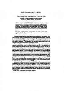
Figure 1 shows a typical model-based development toolchain including an automatic code generator. The specification model (aka physical model ) is designed using a high-level domain-oriented modeling tool. These specification models are typically enriched with implementation details (e.g., a continuous-time controller model is replaced by a discrete-time approximation) resulting in so-called code generation or implementation models. A code generator transforms code generation models into C-code, that the cross compiler translates into object code. The different object codes, including 2 MathWorks reacted to this deficiency by offering several Simulink toolboxes, most notably SimScape, to enable legacy and basic software code are then finally linked to
equation-based physical modeling (SimScape made its debut in the R2007A release of Matlab/Simulink). Unfortunately, despite using the same basic concepts like Modelica, MathWorks decided to create its own, proprietary, physical modeling language. In effect, the huge pool of high-quality (free and commercial) physical modeling libraries already available for Modelica cannot be reused in SimScape. 3 Synchronous languages (Benveniste et al., 2003) are an established technology for modeling, specifying, validating, and implementing real-time embedded applications. Prominent members of the synchronous family include the Lustre (Caspi et al., 1987), Esterel (Boussinot and De Simone, 1991) and Signal (LeGuernic et al., 1991) language. The greatest industry relevancy can be attributed to the Lustre-based commer-
24
cial Scade tool (Sauvage and Bouali, 2006) that is especially used for the development of safety critical software functions. Synchronous languages have no notion of continuous time and are therefore not suited for physical modeling. 4 Attempts to formalize semantic aspects of the Modelica language can be traced back to the very early phases of the language standard where natural semantics based approaches were considered as a help in the language design process (K˚ agedal and Fritzson, 1998) and also as a base for translator generation (Fritzson et al., 2009). However, these previous studies focused rather on general advantages of formal language specifications and were not particularly concerned with high-integrity, embedded code generation.
Thiele et. al., “Towards Qualifiable Code Generation from a Clocked Synchronous Subset of Modelica” a binary that can be executed by an embedded target. TCL4 denotes the highest level of required confidence. Tools classified higher than TCL1 need to be qualified. Required qualification measures are further tied Basic Software Function Software Legacy Software to the usage context, in particular to the criticality MIL Simulation Specification Model of the software function that is realized with the deSpecification Model velopment tool. ISO 26262 further recommends four Enrichment with implementation details Plant principle methods for tool qualification: (i) increased Model confidence from use, (ii) development process evaluCode Generation Model Basic Software Legacy Software ation, (iii) software tool validation, and (iv) developProcess Process Code Generator ment in compliance with a safety standard. While (i) or (ii) are recommended for less critical functions and/or Function Legacy Basic Software C-Code C-Code C-Code tool confidence levels, (iii) or (iv) are considered an adequate choice for highly critical functions and tool Cross-Compiler confidence levels. Object-Code Object-Code Object-Code Note that the output of tools that are not qualiCross-Linker fied can still be used, but require suitable safeguarding measures, e.g., automatically generated code can Binary be passed into a standard assurance process where Figure 1: The generic build process for a model- it is treated like manually written code. The benebased development toolchain with an auto- fit of qualified development tools is that certain safematic code generator (adapted from Schnei- guarding measures, like code reviews on generated code (St¨ urmer et al., 2006), can be omitted. der et al. (2009)). In order to increase the confidence in the toolchain depicted in Figure 1 it is, in principle, possible to apThe development of safety-relevant software typi- ply a number of techniques that have been proposed cally needs to comply to rules described in functional for ensuring safety of compilers. The survey by Frank safety standards. This also affects the used develop- et al. (2008) gives an overview of existing techniques ment tools. A development tool may need to fulfil a and also comments on the suitability of the presented certain level of qualification depending on the severity methods for practical application. In particular Frank of the impact a malfunction in the development tool is et al. conclude that a combination of test-based apexpected to have on a safety-related item. For exam- proaches (as opposed to formal verification-based apple, in the automotive domain the ISO 26262-8:2011, proaches) is the most promising way to improve the Section 11 Qualification of software tools, establishes a reliability of compilers for safety-related applications set of recommendations concerning the needed qualifi- within the automotive industry. Despite plenty reports in the open literature about cations of such software tools. The automatically generated C-code in Figure 1 can (in many cases formal) methods that are in principle also be seen as a low-level intermediate representation capable of increasing confidence levels in compilers or of the model, because it is both the output of the code code generators, detailed reports of actually successgenerator as well as input to the cross compiler for ful tool qualification efforts for automatic code generthe target. If sufficient confidence can be put into ators are rare. Schneider et al. (2009) give a rather the correct functioning of the tool chain, safeguarding comprehensive report on the practical qualification of measures for intermediate representations can be elim- an industrial-strength development tool (an integrated inated. For example, code reviews on automatically code generator tool with target compiler) by a validation suite approach (hence, by a software tool validagenerated code can be omitted. tion method) according to automotive requirements. The approach is centered around an automated test 2.2. Tool Qualification environment that allows the automated execution of Functional safety standards typically classify develop- large numbers of test cases. The number of required ment tools into categories that depend on the impact a test cases is subject to scalability issues so that suitable systematic tool failure (“bug”) has on a safety related language restrictions are an important prerequisite beitem and on the probability that a bug remains unde- fore starting qualification efforts for complex real-world languages. tected by downstream development steps and tools. For example, ISO 26262 defines four categories Regardless of whether the tool qualification method termed Tool Confidence Level (TCL1 – TCL4) where of choice is to develop a new tool according to ap-
25
Modeling, Identification and Control propriate safety standards, or to use a test-based or Elaboration Involves type checking, collapsing the inverification-based approach to qualify an existing tool: stance hierarchy and generation of connection keeping the input language of the code generation equations from connect-equations. The result is a model (see Figure 1) as simple and well-defined as poshybrid differential algebraic equation (DAE) syssible is essential to keep development/qualification eftem consisting of variable declarations, equations forts under control. This regards the number and comfrom equations sections, algorithm sections, and plexity of basic constructs in the language and also the when-clauses for triggering discrete-time behavior. number and complexity of performed transformation Equation Transformation This step encompasses rules in the code generation process. transforming and manipulating the equation sysFurthermore, it is important to understand that tem into a representation that can be efficiently technically tools need to be qualified in the context solved by a numerical solver. Depending on the of a particular system development project and thereintended solver the DAE is typically reduced to fore only qualifiable tools are available on the market. an index one problem (in case of a DAE solver) or Using a qualifiable tool alleviates tool qualification efto an ODE form (in case of numerical integration forts and the project specific tool qualification is usumethods like Euler or Runge-Kutta). ally achieved in close collaboration of the tool user and the tool vendor (Hatcliff et al., 2014). Code generation For efficiency reasons tools typically allow (or require) translation of the residual func2.3. Typical Modelica Code Generation tion (for an DAE) or the right-hand side of an equation system (for an ODE) to C-code that is Compiling Modelica code usually involves substantial compiled and linked together with a numerical code transformation. The following description is a solver into an executable file. slightly adapted reproduction of (Thiele et al., 2012, Section 4.2.5). Figure 2 gives an overview of the compi- Simulation Execution of the (compiled) model. Durlation and simulation process as described by Broman ing execution the simulation results are typically (2010, p. 29). written into a file for later analysis. In the context of code generation for safety relevant systems the typical processing of Modelica models has two problems:
Modelica Model Lexical Analysis and Parsing Compiler front-end
AST Elaboration
Compile Time
Hybrid DAE Equation Transformation & Code generation Compiler back-end
Executable Simulation
Run time
Simulation Result
Figure 2: Outline of a typical compilation and simulation process for a Modelica language tool (Broman, 2010, p. 29).
1. In the Elaboration phase the instance hierarchy of the hierarchically composed model is collapsed and flattened into one (large) system of equations, which is subsequently translated into one (large) chunk of C-code, thus impeding modularization and traceability at the C-code level. 2. In the Equation Transformation phase the equations are extensively manipulated, optimized and transformed at the global model level. The algorithms used in this step are the core elements that differentiate the model compiler tools (quality of implementation). Although the basic algorithms are documented in the literature, the optimized algorithms and heuristics used in commercial implementations are vendor confidential proprietary information. The lack of transparency and simplicity exacerbates tool qualification efforts.
Therefore, the compilation process for simulation (Figure 2) may be significantly different compared to The different phases are: the target code compilation process depicted in FigLexical Analysis and Parsing This is standard com- ure 1. Not only because different compilers are used, piler technology. but also because the target code generator may (need
26
Thiele et. al., “Towards Qualifiable Code Generation from a Clocked Synchronous Subset of Modelica” to) be an entirely distinct piece of software that may share only minimal to no amounts of code with the simulation code generator5 . In particular the target code generator depicted in Figure 1 is only required to understand a Modelica subset that is sufficient for digital control function modeling.
2.4. An Approach Towards a Qualifiable Modelica Code Generator The requirement to keep the input language of the code generation model as simple and well-defined as possible motivated Thiele et al. (2012) in a previous work to propose a subset of Modelica for safety-relevant control applications that would offer a reasonable compromise between language expressiveness and expected effort of tool qualification. The proposed language restrictions were substantiated by providing rationales. However, no evidence was given about the practical feasibility to develop a qualifiable automatic code generator for that language subset. The Modelica subset used in this work is a modified version of the subset proposed in the former paper. In order to allow a clear and brief presentation of the translational semantics the former subset is further reduced to a kernel of representative elements. The resulting language kernel for automated code generation is denoted as mACG-Modelica. The presented approach towards a qualifiable code generator relies on:
The existence of the translation provides: (i) a strong argument for the feasibility to develop a qualifiable code generator for the considered Modelica subset and (ii) a base that can be used to create a gateway from Modelica to a qualifiable code generator that is based on clocked synchronous data-flow language like Scade/KCG (similarly to what has been reported by Caspi et al. (2003) for a translator from Simulink to Scade).
3. Translation to a Synchronous Data-Flow Kernel Language 3.1. The Synchronous Data-Flow Kernel Language (SDFK)
Synchronous data-flow kernel languages have been used in various publications as suitable representation for languages in certain formal methods based research. Instead of reinventing syntax, this work utilizes the synchronous data-flow kernel language6 described by Biernacki et al. (2008). The SDFK is close to Lustre/Scade so that it allows to use well-understood and accepted compilation techniques that have been developed for these languages. Biernacki et al. (2008) formally describe modular code generation from that data-flow kernel into imperative code and note that “The principles presented in this article are implemented in the RELUC compiler of SCADE/LUSTRE and experimented on indus1. A target language which allows the proposition trial real-size examples”. Hence, using that particular that a qualifiable code generator can be imple- SDFK language is attractive since it directly allows mented for it. This language is in the following to reuse the described code generation techniques for referred to as the Synchronous Data-Flow Kernel ACG-Modelica as soon as a translational semantics is available. language (SDFK). In order to keep the following discussion more self2. A representative language kernel for digital con- contained, the syntax and intuitive semantics described trol function development in Modelica (mACG- in (Biernacki et al., 2008, Section 2) are briefly reproduced in the current section: Modelica). A program is made of a list of global type (“td”) 3. A set of translation equations from mACG- and node (“d”) declarations. In order to allow a clear Modelica to SDFK. The semantics of mACG6 Note that the semantics of the synchronous kernel language Modelica are defined in terms of this translation is given informally in (Biernacki et al., 2008). However, it (translational semantics). can be traced back to a formal semantics if necessary. Bier-
5 The
amount of code that can be shared depends on various aspects, particularly on the tool qualification approach. Tool qualification by developing the tool in compliance with a safety standard, needs respective evidence on the development process that is usually not available for existing code. ISO 26262 also lists increased confidence from use as a method that is particularly applicable for more moderate safety requirements and tool validation as method that is also applicable for more safety-critical software — these methods are more amenable to reuse existing code.
nacki et al. (2008) refer to (Cola¸co et al., 2005) for the formal semantics of the clock calculus. Actually, the extended language presented in (Cola¸co et al., 2005) is similar to the one used in (Biernacki et al., 2008). In (Cola¸co et al., 2005) this extended language is formally translated into a more “basic” data-flow kernel language by a source-to-source transformation. For this “basic” data-flow kernel language (Cola¸co et al., 2005, Section 3.1) refers to (Cola¸co and Pouzet, 2003) for a (formal) denotational Kahn semantics (except for the semantics of the modular reset operator “every” which is formally defined in (Hamon and Pouzet, 2000)).
27
Modeling, Identification and Control
Table 1: Expressions in SDFK v
x (a1 , . . . , an ) v fby a
op(a1 , . . . , an )
f (a1 , . . . , an ) every a
a when C(x) merge x (C → a1 ) . . . (C → an )
Values are either immediate values (“i”), e.g., integer values, or they are constructors (“C”) belonging to a finite enumerated type (e.g., the Boolean type is defined as “bool = False + True”). Variables. Tuples. Initialized delays. The first argument “v” (the initial value) is expected to be an immediate value, the second argument “a” is the stream that is delayed. Point-wise applications. To simplify the presentation, “op(a1 , . . . , an )” is a placeholder for any point-wise application of an external function op (e.g., +, not) to its arguments. To improve the readability of examples, the application of classical arithmetic operations will be written in infix form. Node instantiations with possible reset condition “a”. At any instant at which Boolean stream “a” equals “True” the internal state of the node instantiation is reset. To simplify the notation the reset condition “every a” may be omitted which is equal to writing “every False” as reset condition. Sampling operations. Sample a stream “a” at every instant where “x” equals “C”. Combination operations are symmetric to the sampling operation: They combine complementary streams in order to produce a faster stream. “x” is a stream producing values from a finite enumerated type “bt = C1 + . . . + Cn ”. “a1 , . . . , an ” are complementary streams, i.e., at an instant where “x” produces a value at most one stream of “a1 , . . . , an ” is producing a value. At every instant where “x” equals “Ci ” the value of the corresponding stream “ai ” is returned.
and brief presentation, only abstract types and enumerated types are considered in the discussion. A global node declaration “d” has the form “node f (p) = p with var p in D”. Within this node declaration “p” denotes a list of variables while “D” denotes a list of parallel equations. In an equation “pat = a” the pattern “pat” is either a variable or a tuple of patterns “(pat, . . . , pat)” and “a” denotes an annotated expression “e” with its clock “ct”. Table 1 briefly describes various elements that can be part of an expression. The expressions can be extended by the conditional “if /then/else” which relates to the original kernel by the equivalence relation: if x then e2 else e3 = merge x (True → e2 when True(x)) (False → e3 when False(x))
(1)
system. This clock calculus precedes the code generation step (see (Biernacki et al., 2008, Section 2.2) for more details). The syntax of the (clock-annotated) SDFK language is defined by the following grammar: td ∶∶= type bt ∣ type bt = C + . . . + C d ∶∶= node f (p) = p with var p in D p ∶∶= x ∶ bt; . . . ; x ∶ bt D ∶∶= pat = a ∣ D and D pat ∶∶= x ∣ (pat, . . . , pat) a ∶∶= eck e ∶∶= v ∣ x ∣ (a, . . . , a) ∣v fby a ∣ op(a, . . . , a) ∣ f (a, . . . , a) every a ∣ a when C(x) ∣ merge x (C → a) . . . (C → a)
v ∶∶= C ∣ i Note that the clock annotations “ct” have no impact ct ∶∶= ck ∣ ct × . . . × ct on the data-flow semantics of the language. Clocks do ck ∶∶= base ∣ ck on C(x) not have to be explicitly given in the SDFK language, although they are part of the language semantics. For example, instead of writing “((v fby xck )ck +y ck )ck ” it For the translational semantics the expressions “e” are suffices to write “((v fby x) + y)”. Clock annotations extended by the conditional “if /then/else” as defined in the SDFK language are determined automatically in (1). by a clock calculus which is defined as a type inference Some of the traditional operations supported by Lus-
28
Thiele et. al., “Towards Qualifiable Code Generation from a Clocked Synchronous Subset of Modelica” tre are related to SDFK through the following equivalences:
Lustre
SDFK
e when x = e when True(x) Lustre’s sampling operation, where x is a Boolean stream. e1 − > e2 = if True fby False then e1 else e2 Lustre’s initialization operator. pre(e) = nil fby e Lustre’s uninitialized delay operator. The shortcut nil stands for any constant value e which has the type of e. It is the task of the initialization analysis to check that no computation result depends on the actual nil value.
In order to illustrate the effect of these operators Table 2 shows example applications of these operators to streams of values. Table 2: Examples for applying the SDFK operators Stream/Expression h x y v fby x x+y x −> y pre(x) z = x when True(h) t = y when False(h) merge h (True → z) (False → t)
Stream values True x0 y0 v x 0 + y0 x0 nil x0 x0
False x1 y1 x0 x1 + y1 y1 x0 y1 y1
True x2 y2 x1 x2 + y2 y2 x1 x2 x2
False x3 y3 x2 x3 + y3 y3 x2 y3 y3
... ... ... ... ... ... ... ... ... ...
modification “mo” (compared to Modelica modifications are more restricted, see Section 5). Parameters can be declared with modification expression “parameter t x = me;”, or without modification binding “parameter t x;”7 . The use of component dot accesses for parameters is not supported in the presented translation in order to simplify the presentation. Allowing it would require to additionally introduce component dot access normalization (Figure 21) and “dummy” equation generation (Figure 22) in a slightly adapted form for parameters in the normalization step. For the actual translation step it would be necessary to translate all parameters not only to node input arguments, but also to node outputs arguments. This seems to make the translation harder to understand without adding much additional conceptual value8 . Equations “D” are either connect equations “connect(cx, cx)” or equations of the form “cx = e”, where “cx” is a single variable (the unknown of the equation, which is either accessed by a simple identifier “x”, or by using a component dot access “x.x”) and “e” is an expression (hence, equations are more restricted than in Modelica where the unknown of an equation may appear at an arbitrary place). Similar to SDFK an abstract n-ary operator “op(e, . . . , e)” is provided to simplify the presentation (nevertheless the provided examples will be presented using concrete Modelica operators). The syntax of mACG-Modelica is defined by the following grammar: td ∶∶= type t; bd ∶∶= block id p equation D end; cd ∶∶= connector id = c t; c ∶∶= input ∣ output
3.2. mACG-Modelica To allow a clear and brief presentation of the translational semantics the Modelica language is reduced to a small subset of elements that is considered to be representative for data-flow based digital control functions. The resulting language kernel is denoted as mACGModelica. A program is made of a list of global type (“td”), connector (“cd”) and block (“bd”) declarations. Only abstract types “t” are considered (nevertheless the provided examples will use concrete Modelica types, e.g., replacing “t” by “Real”). Connectors “cd” have either input or output causality. A block declaration “d” has the form “block id p equation D end;”, where “id” is the name of the block, “p” contains the local component declarations and “D” the equation declarations. A component declaration “p” can be modified by a
p ∶∶= p p ∣ t x; ∣ t x mo; ∣ c t x; ∣ c t x mo; ∣ parameter t x; ∣ parameter t x = me; mo ∶∶= (ar , . . . , ar) ar ∶∶= id = me D ∶∶= D D ∣ eq; 7 Modelica
semantics require that modification bindings for parameters have parametric or constant variability (Modelica Association, 2012, Section 3.8). This needs to be ensured by a statical check before the translation (for conciseness the description of that check is omitted). 8 In addition to transforming parameters to input arguments of a (C-) function, it becomes necessary to make them available as output arguments. E.g., consider “block A parameter Real p1 = 0.1; end A;” which is instantiated in “block B A a(p1=0.2); parameter Real p2 = a.p1; end B;” and note that a.p1 needs to return the value 0.2. If A is translated to a function, there needs to be an input argument to set p1 and an output argument to retrieve its value.
29
Modeling, Identification and Control e ∶∶= v ∣ cx ∣ op(e, . . . , e) ∣ previous(x)
c) Creating a fresh block that instantiates the top-level block as a component with normalized component modifications.
∣ if e then e else e me ∶∶= v ∣ x ∣ op(me, . . . , me) ∣ if me then me else me
2. Translation to the SDFK language.
eq ∶∶= cx = e ∣ connect(cx, cx)
Normalization and translation are defined as a system of mutually recursive functions. The normalization is needed in order to transform mACG-Modelica x ∶∶= id into a (simplified) normalized form which is the basis v = value for the translation to the SDFK language. The syntax id = identifier for the normalized mACG-Modelica language can be found in Section 3.5. Using a multilevel translation approach facilitates inAbstract types “t” encompass predefined primitive types and user-defined structured types (blocks and cluding further language elements, as long as a sourceconnectors). The set “B” is introduced to denote the to-source transformation into a smaller language kerset of all predefined primitive types, particularly Mod- nel can be given. The generation of connection equations is a good example for this: it eliminates the conelica’s “Boolean”, “Integer”, and “Real” types. From all the clocked synchronous language elements nector declarations and connect equations by replacthat are listed in (Modelica Association, 2012, Chap- ing them with simple variable declarations (using the ter 16) only “previous” appears in the grammar proper input/output causalities) and simple equations above. The clock conversion operators are omitted — of the form “x = e”. Hence, the multilevel translation for practical applications this is not as restrictive as it approach provides a path to incrementally extend the may appear at a first glance. Section 5 briefly com- mACG-Modelica subset to more comprehensive subsets for control function development (see also the disments on that. Also the operator “interval(u)” is missing in the cussion in Section 5). grammar. This operator is considered to be available as external function call or macro — the time span be- 3.4. The Normalization tween a previous and a present tick is typically only known by the environment that triggers the execution The normalization is presented by using example code of the synchronous data-flow program. Consequently, snippets that illustrate the required source-to-source that value needs to be provided by the runtime envi- transformation. The formal translation equations are ronment. In the case of single-rate programs (i.e., if no rather heavy and are therefore provided as a suppleclock conversion operators are supported) the interval mentary part of the appendix, Section B. The line numbers of the code snippets are consecuduration is simply the duration between two ticks of tively incremented, so that descriptive text can refer to the base clock, in case of multi-rate programs it bethem. Once a class/type is declared, it may reappear comes more complicated and the value depends on the in subsequent code snippets. specific clock that is associated to the operators argument ”u”. 3.4.1. Generation of Connection Equations cx ∶∶= x . x ∣ x
3.3. A Multilevel Translation Approach
Connector Declarations Connector declarations The translation to the SDFK language is rather com- (line 1–2) are replaced by their corresponding plex. In order to keep the translation manageable and short class definition (e.g., In ↦ input Real, comunderstandable the translation is subdivided into sev- pare line 4 ↦ 10 and Out ↦ output Real, compare line 5 ↦ 11). eral steps. The two major steps are: 1. Normalization of mACG-Modelica (formulated as source-to-source transformation). This step is again subdivided in: a) Generation of connection equations. b) Stripping of parameter modifications, normalizing instance modifications and extracting instance dot accesses appearing in expressions.
30
1 2 3 4 5 6 7 8
connector In = input Real; connector Out = output Real; block A In u; Out y; equation y = u; end A; source
↧normal
Thiele et. al., “Towards Qualifiable Code Generation from a Clocked Synchronous Subset of Modelica”
9 10 11 12 13 14
block A input Real u; output Real y; equation y = u; end A;
35 36 37 38 39
source 40
Connect Equations The connect equations are replaced by simple equations of the form “x = e”. Note that the causality is not directly encoded in the connect equations, so it has to be inferred from the variable declarations.
41 42 43 44 45 46
15 16 17 18 19 20
block B In u; A a1; equation connect (u, a1.u ); end B; source
21 22 23 24 25 26
↧normal
block B input Real u; A a1; equation a1.u = u; end B;
47 48 49 50 51 52 53
55 56 57 58
Parameter Stripping Parameter modifications in a class are stripped away.
59 60 61
28 29 30
block C parameter Real k; parameter Real Td; parameter Real _pi_kd = _pi_Td *2; parameter Real _pi_Td =Td; PI pi(kd=_pi_kd , Td= _pi_Td ); end C;
block D output Real y; A a; equation a.u = 3; y = a.y + 2; end D; source
3.4.2. Parameters, Instance Modifications, and Dot Accesses
block PI parameter Real kd = Td *2; parameter Real Td = 0.1; end PI;
↧normal
Extraction of dot accesses Instance dot accesses in RHS equations are extracted and replaced by fresh substitute variables.
54
27
block C parameter Real k; parameter Real Td=0.2; PI pi(Td=Td); end C;
62
↧normal
block D output Real y; A a; Real _a_y; equation a.u = 3; _a_y = a.y; y = _a_y + 2; end D;
3.4.3. Generation of Top-Level Instantiation Blocks
If a block is the top-level block for code generation, it needs a special treatment: parameter modifications 31 block PI in that block should not be lost by stripping them 32 parameter Real kd; away. To achieve that without requiring a special case 33 parameter Real Td; treatment in the preceding translation step, a fresh 34 end PI; block that instantiates the top-level block with normalized instance modifications is inserted for every block. Parameter Modifications at Instantiated Blocks All Hence, block C (line 35–39) would introduce the fresh parameters of an instantiated block are extracted, block: merged with applicable instance modifications and in- 63 block _Inst_C parameter Real _c_k; troduced as fresh parameters with a modification ex- 64 65 parameter Real _c_Td =0.2; pression. C _c(k=_c_k , Td=_c_Td ); Note that the parameter modification from line 28 is 66 extracted and reintroduced in line 43, while the modifi- 67 end _Inst_C ; Inputs and outputs of a block are simply propagated cation from line 29 is overridden by the instance modification in line 28 before being assigned to the fresh through, e.g., block D (line 47–53) would introduce the fresh block: parameter _pi_Td in line 44. source
↧normal
31
Modeling, Identification and Control
68 69 70 71 72 73
block _Inst_D output Real y; D _d; equation y = _d.y; end _Inst_D ;
3.5. Normalized mACG-Modelica
arguments. Outputs are mapped to node return values. A lexicographic order relation on node input and output arguments ensures an unambiguous mapping. Delays and the start values of their arguments are mapped to initialized delays (e.g., “previous(x)” ↦ “0 fby x”, if “x(start=0)”, compare line 6,8 ↦ 16). 1 2
After the normalization all component dot accesses are extracted from nested expressions. All “connectequations” are resolved. At instance declarations all available parameters are set as modifications. In a block that instantiates another block, any output of the instantiated block is at least accessed once. The syntax of normalized mACG-Modelica is defined by the following grammar:
3 4 5 6 7 8 9 10
block PI input Real u; output Real y; parameter Real kd; parameter Real Td; Real x(start =0); equation x = previous (x) + u/Td; y = kd*(x + u) end PI; normal
td ∶∶= type t; d ∶∶= block id p equation D end id; c ∶∶= input ∣ output p ∶∶= p p ∣ t x; ∣ t x mo; ∣ c t x; ∣ c t x mo; ∣ parameter t x ∣ parameter t x = e; mo ∶∶= (ar , . . . , ar)
11 12 13 14 15 16 17
↧sdf k
node PI (Td:real , kd:real , u:real) = y:real with var x:real in x = 0 fby x + u/Td and y = kd*(x+u)
ar ∶∶= id = e D ∶∶= D D ∣ eq; e ∶∶= v ∣ x ∣ op(e, . . . , e) ∣ previous(x) ∣ if e then e else e eq ∶∶= x = e ∣ x . x = e ∣ x = x . x x ∶∶= id v = value
Parameters with Modification Parameters with modification bindings are mapped to local variables and equations. 18 19 20 21
id = identifier
normal
22 23
3.6. The Translation
block E parameter Real k1 = 2*k2; parameter Real k2 = 4; end E;
24 25 26
↧sdf k
node PI () = with var k1:real , k2:real in k1 = 2*k2 and k2 = 4
After normalization (Section 3.4), the model is available in the normalized mACG-Modelica language (Section 3.5). This form allows a more straightforward Instance Modifications and Dot Access Instance translation to the SDFK language (Section 3.1) which modifications and instance dot accesses are mapped to will be described in the following sections. function application like node instance calls. Any normalized mACG-block is directly mapped to an SDFK node — no context information from sur- 27 block F 28 input u; rounding blocks is needed. 29 30
3.6.1. Intuitive Translation
31 32
Inputs, Outputs, Parameters without Modification, and Initialized Delays Inputs and parameters without modification bindings are mapped to node input
32
33 34 35
output y; parameter Real _pi_Td = 0.1; parameter Real _pi_kd = 2; PI pi(kd=_pi_kd , Td= _pi_Td ); Real _pi_y; equation pi.u = 0.1*u;
Thiele et. al., “Towards Qualifiable Code Generation from a Clocked Synchronous Subset of Modelica”
36 37 38
_pi_y = pi.y; y = _pi_y + 2; end F; normal
39 40 41 42 43 44 45 46 47
↧sdf k
node F (u:Real) = y:real with var _pi_Td :real , _pi_kd :real , _pi_y :real in _pi_Td = 0.1 and _pi_kd = 2 and _pi_y = PI(_pi_Td , _Pi_kd , 0.1*u) and y = _pi_y + 2
3.6.2. Formal Translation Semantics This section defines the translational semantics for the normalized mACG-Modelica language. Hence, semantics of modeling constructs in normalized mACGModelica are expressed in terms of constructs from the SDFK language. Notation The following notation shall be used: A sequence of elements (e1 , . . . , en ) is frequently written as a list [e1 ; . . . ; en ] for which an operator “+” is defined so that if p1 = [e1 ; . . . ; en ] and p2 = [e′1 ; . . . ; e′k ] then p1 + p2 = [e1 ; . . . ; en ; e′1 ; . . . ; e′k ] provided ei ≠ e′j for all i, j such that 1 ≤ i ≤ n, 1 ≤ j ≤ k. [] denotes an empty list. Furthermore, e1 ∈ p1 shall denote that e1 appears as an element in p1 . Frequently, elements ei are tuples (e.g., ei = (xi , ti )). Especially if tuples encode variable names and their associated types an alternative notation is preferred in which “,” is replaced by “∶” and the parentheses are dropped (e.g., ei = xi ∶ ti ). The underscore “ ” is used as a placeholder for entries which are irrelevant in the specific context. Mutually recursive functions “Function(context) (element)” are used for defining a transformation of an element within a context. To keep the notation concise the definition of a function is often overloaded — its actual interpretation should be clear from the context. Additionally, the transformation relies on a suitable lexicographical order relation “