problem and recently developed approaches for robust graph optimization can .... In the most general graphical model (a), there are no connections between the ...
Published in Proc. of IEEE Intl. Multi-Conf. on Systems, Signals, and Devices (SSD), 2012. DOI: not yet available c
2012 IEEE. Personal use of this material is permitted. Permission from IEEE must be obtained for all other uses, in any current or future media, including reprinting/republishing this material for advertising or promotional purposes, creating new collective works, for resale or redistribution to servers or lists, or reuse of any copyrighted component of this work in other works.
Towards Robust Graphical Models for GNSS-Based Localization in Urban Environments Niko S¨underhauf and Peter Protzel Department of Electrical Engineering and Information Technology Chemnitz University of Technology, 09126 Chemnitz, Germany {niko.suenderhauf, peter.protzel}@etit.tu-chemnitz.de
Abstract—Our paper proposes to adapt recent advances in the SLAM literature (Simultaneous Localization and Mapping) to the problem of multipath mitigation in GNSS-based localization. We argue that such localization problems can be modelled as factor graphs and solved using efficient nonlinear least squares approaches that exploit the sparsity inherent in the problem formulation. This way, satellite observations that are subject to multipath errors can be understood as outliers in the optimization problem and recently developed approaches for robust graph optimization can be applied to mitigate these effects.
I. I NTRODUCTION SLAM (Simultaneous Localization And Mapping) has been a very active and almost ubiquitous problem in the field of mobile and autonomous robotics for over two decades. For many years, filter-based methods have dominated the SLAM literature [1], but a change of paradigms could be observed recently, that led the developments away from filters towards optimization-based methods. Although such optimization-based approaches are known to the community since the work of Lu and Milois in 1997 [2], they have only recently begun to become more popular as efficient algorithms for solving the underlying optimization problems are now available. The most prominent recent examples have been g2o [3] and iSAM2 [4]. In contrast to filter-based methods, optimization-based approaches build upon efficient algorithms for nonlinear least squares optimization that exploit the sparsity inherent in the SLAM problem. This way, largescale SLAM problems containing several 10k variables (poses, landmarks) and constraints (observations, loop closings) can be solved in a matter of seconds on standard hardware. However, it is commonly known that least squares methods are not by default robust against outliers. In SLAM, such outliers arise mostly from data association errors like false positive loop closures etc. In recent previous work [5], [6] we developed an approach for robust optimization for pose graph SLAM problems in the presence of such outliers. This paper discusses the applicability of this robust graphbased optimization to the problem of GNSS1 -based localization. As we will see, the general idea of altering the topology of a factor graph during the optimization (or the equivalent probabilistic interpretation of adapting the information matrices associated with some of the constraints during the optimization) that was developed in [5], is rather universal and 1 Global
Navigation Satellite System, e.g. GPS, Galileo, GLONASS.
can be applied in other optimization-based problem domains where outliers can occur. The outliers in the scenario of GNSS-based localization are miscalculated pseudoranges that are caused by so called multipath effects. These multipath affected pseudorange measurements play the same critical role in GNSS-based localization as false positive loop closure constraints and data association errors play in the SLAM scenario. In the following, the GNSS-based localization problem is shortly introduced, before we demonstrate how it can be expressed as a least squares optimization problem and modelled using a factor graph. We then explain how to apply the robust optimization method developed earlier and show results from simulation as a proof of concept. II. T HE GNSS-BASED L OCALIZATION P ROBLEM From a roboticist’s perspective, GNSS-based localization is a 3D localization problem with range-only observations to distant landmarks. The landmarks in this scenario are the satellites which are uniquely identifiable via their transmitted PRN code. The positions of the observed satellites / landmarks in space are known since each satellite transmits ephemeris parameters which describe its orbit. The ranges from the receiver to the satellites are not observed directly, but rather calculated from the signal transit time. This is done by comparing the timestamp that is included in the received signal and specifies when the signal was sent from the satellite, with the local time at the receiver in the moment the signal is received: ρ = c · (trecieve − ttransmit ) where c is the speed of light. The quantity that is to be estimated from these pseudoranges ρ is the location of the receiver in 3D space, thus x = (x, y, z)T . Since the state space has three degrees of freedom, in one would expect three observations to be sufficient to solve the problem. However, the pseudoranges are subject to a number of possible error sources. The most important are: • receiver clock errors • ionospheric and tropospheric propagation errors • satellite clock and ephemeris errors • multipath errors Receiver clock errors have probably the largest implications on the design and working principles of GNSS systems. They occur because it is not possible (or at least not feasible for economic reasons) to keep the receiver clocks exactly
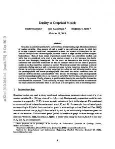
Fig. 1. The multipath problem in an urban canyon: The direct line of sight (red line) from the satellite to the receiver on the ground is blocked by a building. The signal reaches the receiver via a reflection (blue line), causing a range error of the observed pseudo-range. Since GNSS localization is based on measuring the pseudo-range between the sender and the receiver, the position estimate is distorted.
synchronised to the transmitter clocks. The dilemma is solved elegantly by including the unknown receiver clock error into the state space that is to be estimated: x = (x, y, z, δ clock )T . This way, the correction term δ clock covers for the differences between the GPS time used by the satellites and the local receiver time. Since now there are four unknowns that have to be estimated, a minimum of four pseudorange satellite observations are necessary. A common challenge for GNSS-based localization is the multipath problem, that occurs for instance in urban areas with high buildings blocking the direct line of sight to at least some of the available satellites. This scenario is also referred to as urban canyon. Fig. 1 illustrates the basic problem: Although the direct line of sight to a satellite is blocked, its signal may still reach the receiver on the ground via one or several reflections on building structures or the ground. Since the signal path is longer for the reflected signal, ranging errors occur that can either prolongate the observed pseudo-range or, due to correlation effects, shorten it [7, ch. 5.5]. Multipath effects can also occur when the direct line of sight is free. In this situation, the signal is received directly, but is also reflected on a building or another structure in the vicinity of the receiver. Hence the signal is received multiple times which leads to correlation errors. III. M ULTIPATH I DENTIFICATION AND M ITIGATION – R ELATED W ORK Different approaches for multipath mitigation are known to the literature. [7] divides the approaches into different strategies: Spatial processing techniques try to optimize the receiver antenna design (e.g. using choke ring antennas or antenna arrays) to decrease the possibility of receiving a reflected signal or incorporate information gained by long-term observations (spanning from on day to another). The second type of techniques mentioned by [7] are time-domain approaches that try to identify multipath errors by post-processing and evaluating the received signals from the satellite in the receiver. These approaches are rather low-level and operate on the radio signal level.
It is curious that RANSAC-like algorithms [8] seem to have only recently found their way into the GNSS-community [9], [10]. Roughly similar approaches have been summarized under the term RAIM (Receiver Autonomous Integrity Monitoring) but appear to have mostly expected only a single outlier among the satellite observations [10] which is inadequate given the increasing number of usable satellites, especially when considering multi-constellation applications. [11] however discusses the application of RAIM in the occurrence of several simultaneous satellite failures. [12] proposes to actively determine occluded satellites with the help of an omnidirectional infrared camera mounted on the vehicle. IV. M ODELLING THE GNSS- BASED L OCALIZATION P ROBLEM AS A FACTOR G RAPH Factor graphs are bipartite undirected graphs and have been proposed by [13] as a general tool to model factorizations of large functions with many variables into smaller local subsets. The idea can be applied to probabilistic problems like SLAM or GNSS-based localization. The key idea is that a joint probability distribution can be expressed as a product over several single factors (of course adhering the conditionalQ dependencies Q etc.), e.g. P (X|U, Z) = i P (xi |ui , xi−1 ) · i,j P (xi |zj ) where xi are for instance the vehicle states, ui are control inputs and zj are measurements of any kind. Factor graphs contain two types of nodes: one for variables and the other for probabilistic constraints (the factors). In the context of GNSS-based localization, one type of node represents the unknown vehicle state variables xt , while the other type of node encodes the relations (conditional probabilities) between them (e.g. via a motion model) or the pseudorange measurements. Fig. 2 illustrates this concept. In the following we explain the state space vertex and a number of factors suitable for the problem of GNSS-based localization. A. The Vehicle State Vertices The state space contains at least the 3D position of the vehicle as well as the receiver clock error, leading to a state space that is at least 4-dimensional: x ∈ R4 = (x, y, z, δ clock )T
(1)
This state space may be extended by jointly estimating the vehicle orientation θ, velocity v, rotation rate ω or the clock error drift δ˙ clock , depending on the requirements and which other sensors are used. Estimating the vehicle acceleration a or road curvature 1/r would also be possible. B. The Pseudorange Factor A number of satellites are observed from every vehicle state xt , each providing a pseudorange measurement ρtj . Given the receiver position xx,y,z and the position of the observed t satellite xSAT tj , the expected pseudorange measurement is given by the measurement function x,y,z h(xt , j) = kxSAT k + δ EarthRotation + δ Atmosphere + xδt tj − xt
clock
(2)
...
(a)
(b)
Fig. 2. Two vehicle state nodes with their associated pseudorange factors (green). In the most general graphical model (a), there are no connections between the vehicle state nodes, since they are considered conditionally independent. In (b), a state transition or motion model factor joins two successive vehicle nodes.
The terms δ EarthRotation and δ Atmosphere correct ranging effects caused by the earth’s rotation and atmosphere (ionospheric and tropospheric propagation errors). δ EarthRotation is given by δ EarthRotation = ω Earth
SAT xSAT tj · yt − ytj · xt c
(3)
with ω Earth the earth’s rotation rate and c the speed of light. If we assume the measured pseudorange ρtj is given by the measurement function h(xt , j) plus a zero-mean Gaussian error term, thus ρtj = h(xt , j) + N (0, Σtj )
(4)
then the error function of a single pseudorange factor is given as 2 2 kepr (5) tj kΣtj = kh(xt , j) − ρtj kΣtj with Σtj the covariance associated to the pseudorange measurement ρtj . Notice that minimizing above error over xt corresponds to maximizing the likelihood function L(ρtj |xt ) ∼ N (h(xt , j), Σtj ). C. The State Transition Factor Besides the obligatory pseudorange factors, additional factors can be modelled to incorporate more information or sensor data. A possible way to account for the receiver clock error is Clock to model it as either constant over time, i.e. δt+1 = δtClock + λ where λ is a zero-mean Gaussian. Another possibility is to use a a constant drift model, i.e. � Clock δt+1 = δtClock + δ˙tClock ∆t + N 0, σtClock (6) � ˙δ Clock = δ˙ Clock + N 0, σ ClockDrift (7) t+1
t
t
For the latter case, the error function associated with the state transition factor is
� Clock � � Clock � 2
δt
δ + δ˙tClock ∆t st 2
ket kΣstt = − ˙t+1 (8) Clock
˙δ Clock δt+1 t Σst t
Σstt
diag(σtClock , σtClockDrift )
= is, as usual, the covariance matrix associated with the state transition factor at time t. D. The Motion Model Factor A variety of motion models can be applied in the context of vehicle localization or motion estimation. For instance, [14] lists and evaluates six different types. As an example, the constant velocity and turn rate model (CTRV) is used here
to formulate a motion model factor. Notice however that any other model from [14] could be used as well. For the CTRV model, the vehicle state space has to be extended to include the vehicle orientation θ, the velocity v and the turn rate ω. Following [14], the motion model operates in 2D space only, thus does not affect the z coordinate of the vehicle. Therefore, the orientation is specified by only one angle, instead of three angles or a quaternion. With the motion model function f CTRV , the vehicle state xt evolves as xt+1 = f CTRV (xt ) + N (0, Σmm t )
(9)
Given this, we can define the motion model factor’s error function as 2 = kf CTRV (xt ) − xt+1 k2Σmm kemm t kΣmm t t
with xt = (x, y, z, δ
T
Clock
(10)
CTRV
, θ, v, ω) and f defined as: xv � θ ω θ t ) ∆t) − sin(x + x sin(x ω t t t x � xvtt xω cos(xθt ) − cos(xθt + xω t ∆t) t 0 xt+1 = f CTRV (xt ) = xt + 0 ω xt ∆t 0 0 (11) if xω t 6= 0. Otherwise we have: v xt cos(xθt )∆t xvt sin(xθt )∆t 0 CTRV 0 (12) xt+1 = f (xt ) = xt + 0 0 0 E. The State Prior Factor With reliable odometry information (i.e. forward velocity and yaw rate in this scenario) available from the vehicle’s internal sensors, we can incorporate them using state prior factors. For instance, if the state is xt = (x, y, z, δ Clock , θ, v, ω)T as defined above, we can define the state prior factor to be 2 2 kestp t kΣstp = kxt − ζ t kΣstp t
(13)
t
Where ζ t contains the available prior information for the vehicle state at time t. Notice that if only some of the entries in the prior ζ t are actually available (e.g. only v and ω), the entries in the information matrix associated with the unavailable entries can simply be set 0 so that they will not have any influence during the optimization. F. Solving for the Maximum a Posteriori Solution When only the pseudorange measurements are given, the maximum a posteriori solution for a single vehicle state xt is found by solving the least squares problem X pr x∗t = argmin ketj k2Σtj (14) xt
j
Similarly, we can solve for a set of vehicle states X = {xt }: X pr X ∗ = argmin (15) ketj k2Σtj X
tj
Any additional factors that account for further measurements and sensor data can be easily incorporated by extending the error function. For instance to incorporate motion model and state transition factors, we solve X pr 2 X ∗ = argmin + kestt k2Σstt (16) ketj k2Σtj + kemm t kΣmm t X
tj
and so forth.
(a)
(b)
Fig. 3. (a) A vehicle state vertex with three switched pseudorange factors espr (green), the associated switch variables and their prior factors esp (black). (b) Illustration of a more complex factor graph. The switch variables are connected by switch transition factors eswt (yellow) and the state transition factors est (blue) connect the state vertices.
V. T OWARDS A P ROBLEM F ORMULATION ROBUST TO M ULTIPATH E RRORS If multipath observations occur, some of the pseudorange observations are outliers to our least squares optimization problem. It is generally known that least squares methods are by default not robust against such outliers and that even a single outlier can have catastrophic effects on the estimation result. Our main idea to increase the robustness of the optimization is that the topology of the factor graph representation should be subject to the optimization instead of keeping it fixed. This is achieved by introducing another type of hidden variable into the problem formulation: A switch variable stj is associated with each factor that could potentially represent an outlier. The optimization now works on an augmented problem, searching for the joint optimal configuration of the original variables and the newly introduced switch variables, hence searching the optimal graph topology. These ideas were developed in the context of SLAM in [5], [6]. We describe their application to the GNSS-based localization problem in the following. A. The Switched Pseudorange Factor By combining the pseudorange factor from section IV-B with the newly introduced switch variables, we gain the switched pseudorange factor: 2 2 kespr tj kΣtj = kΨ(stj ) · (h(x, j) − ρtj )kΣtj
(17)
The function Ψ is called the switch function. This switch function is defined as Φ : R → [0, 1], i.e. it is a mapping from the continuous real numbers to the interval [0, 1], defined on R. Different switch functions can be defined, e.g. a step function, or a sigmoid. However, our experiments in earlier work showed that a simple linear function of the form : stj < 0 0 1 ωtj = Ψlin (s ) : R → [0, 1] = s : 0 ≤ stj ≤ a (18) tj a a tj 1 : stj > a with parameter a = 1 is a suitable choice. The idea behind the switch variables is that the influence of a pseudorange measurement can be removed by driving the associated switch variable stj to a value so that ωtj = Φ(stj ) ≈ 0. Notice that it is not possible to use the weights ωtj directly as variables in the optimization, since they are
only defined on the interval [0, 1], which is not suitable to the applied least squares optimization approaches that require continuous domains. The influence of the switch variables can be described and understood in two equivalent ways: In the topological interpretation, a switch can enable or disable the constraint edge it is associated with, thus literally remove it from the graph topology. In the probabilistic interpretation, the switch variable influences the information matrix of the factor it is associated with and can drive it from its original value to zero, thus increasing the covariance associated with this factor until infinity. It has been shown that both interpretations are equivalent [5]. To prevent the optimization from simply rejecting all pseudorange observations, an additional switch prior factor is needed that anchors each switch variable stj at its initial value γtj . It is defined as: 2 2 kesp tj kΞtj = kstj − γtj kΞtj
(19)
Combining these two factors leads to the extended robust problem formulation: X spr 2 X ∗ = argmin ketj k2Σtj + kesp (20) tj kΞtj X
tj
Fig. 3 illustrates this extended formulation for a single vehicle state variable. Notice how each pseudorange measurement is associated with its own switch variable. B. The Switch Transition Factor In contrast to the switch variables in the pose graph SLAM problem, the switch variables in the GNSS-based localization problem are not independent: If a satellite j is observed from two successive vehicle locations xt−1 and xt , then stj is likely to be equal to st−1,j . We can capture this conditional dependence and model P (sij |st−1,j ) as a Gaussian with � P (stj |st−1,j ) ∼ N st−1,j , Σswt (21) tj which leads us to the switch transition factor 2 2 keswt tj kΣswt = kstj − st−1,j kΣswt tj
tj
(22)
Position Error
Vehicle Trajectory Estimate 150
Non−Robust Result Robust Estimation Result Position Error [m]
400 300
y [m]
200 100
100
50
0 −100 0 0
−200 Ground Truth Non−Robust Result Robust Estimation Result
−300 −400 −600
−400
−200
0 x [m]
200
400
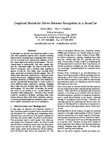
Fig. 4. The estimated vehicle trajectories from the simulation. The ground truth is plotted in green. The conventional least squares estimate (blue) produces many gross errors due to the simulated multipath observations. In contrast, the proposed robust estimate (red) is able to very accurately retrieve the driven trajectory.
that can be easily incorporated as an additional factor into the overall optimization problem. Using the switch transition factors, we would solve X spr 2 swt 2 X ∗ = argmin ketj k2Σtj + kesp (23) tj kΞtj + ketj kΣswt X
tj
tj
for the maximum a posteriori estimate of X. More factors (e.g. a motion model) can be incorporated in the same convenient way. VI. P ROOF OF C ONCEPT To show the feasibility of the proposed robust optimization approach for multipath mitigation, we set up a simple simulation environment in Matlab and implemented the factors mentioned above using the publicly available g2o [3]. In the simulation, a vehicle is driven on a double-8-shaped trajectory while observing a number of satellites. These satellite observations are randomly spoiled by gross pseudorange errors to simulate multipath effects. Fig. 4 shows the ground truth trajectory in green and the trajectory estimate that results from a conventional least squares solution in blue. This conventional solution used the pseudorange factors epr as defined in IV-B. The large trajectory errors resulting from the simulated multipath observations are clearly visible in Fig. 4. The RMSE (root mean squared error) from the ground truth is 7.99 m but the maximum deviation is almost 180 m. When replacing the pseudorange factors with the proposed switched pseudorange factors, the estimation results improve. The mean error decreases to 1.54 m and only a single position is still under the influence of multipath errors: This single outlier is responsible for the maximum error of 154.14 m. The best result in the simulation was achieved when combining the switched pseudorange factors with the state transition model. This successfully removed all outliers from the dataset and results in a mean and maximum error of 1.32 m
200
400
600
800 1000 Timestamp [s]
1200
1400
1600
1800
Fig. 5. Estimation errors for the conventional least squares and the proposed robust solution (red) for every vehicle pose.
and 4.67 m respectively. The detailed results and the required times until convergence are summarized in Table I. The superior quality of the proposed robust solution in comparison to the conventional least squares estimate is apparent from Fig. 5 that compares the individual position errors for every vehicle pose. VII. C ONCLUSIONS AND O UTLOOK As we have seen, since finding the solution for the position of the GNSS receiver on the ground is a least squares problem, it can be conveniently modelled as a factor graph. Furthermore, the proof of concept revealed that the general idea of making the topology of the factor graph subject to the optimization process can be beneficially applied in the GNSSbased localization domain. By associating a switch variable to each of the pseudorange measurements, the optimization is able to identify and remove multipath observations that would otherwise severely bias the position estimate. While the results presented above are merely a proof of concept and the simulation environment is rather prototypical and does not capture the complex real-world effects and dependencies of measurement errors, we feel that the achieved results are sufficient to motivate further work on the proposed ideas. In the future we will therefore work towards evaluating the proposed approach on a real-world dataset. In its general structure, the GNSS-based least squares localization problem is not different from the problems we encounter in SLAM. In fact, it shares the same inherent sparsity of the SLAM problem and can therefore be solved efficiently by applying the same tools, like g2o [3] or iSAM [4]. A key difference to the SLAM problem however is that GNSS-based localization is usually understood as an online problem, i.e. it has to be solved while new measurements and observations arrive. In SLAM, we are sometimes satisfied with an offline or batch solution, after all the data has been gathered. However, since efficient methods for incremental optimizationbased smoothing are available (especially iSAM and iSAM2 [4]), we can solve the GNSS-based localization problem online if it is required and still keep the factor graph representation to apply the robust approach that we proposed.
TABLE I P OSITION ERRORS AND CONVERGENCE TIME FOR THE F IGURE -8 DATASET. Method
Used Factors
non-robust optimization robust optimization
epr espr , espr ,
Median [m]
Mean [m]
Max [m]
Time [s]
1.65 1.35 1.32
7.99 1.54 1.39
179.58 154.14 4.67
0.4 7.5 9.6
esp esp , est
road surfaces. These promising ideas will have to be pursued further and evaluated in future work. Finally, the more general question of filtering vs. optimization-based smoothing for information fusion will have to be discussed in future work. R EFERENCES
Fig. 6. By extending the factor graph illustrated in Fig. 3(b), one can incorporate factors between the vehicle variable and a known map (pink). It would even be possible to exchange information between several other vehicles in the surrounding (using vehicle-to-vehicle communication) and model these additional constraints with inter-vehicle factors (cyan). The other depicted factors are pseudorange factors (green), switch priors (black), switch transition factors (yellow), state transition (blue) and motion model factors (red).
The application of efficient and robust optimization-based approaches to the problem of GNSS-based localization may have strong potential that should be actively pursued in future research. As we have seen in this paper, factor graphs are a powerful tool that allow convenient modelling of vehicle states and satellite observations and the probabilistic constraints between them. Additional information, like from a priori known maps can be easily incorporated into this framework by introducing additional factors. Also in the context of multi-vehicle or cooperative localization where information is exchanged between vehicles or additional roadside devices, factor graphs and efficient robust optimization-based solvers that perform incremental smoothing may be a feasible alternative to filter approaches commonly used today. Fig. 6 illustrates an exemplary factor graph with two vehi[1] [2] cles xt and xt . Both vehicles can exchange information by means of vehicle-to-vehicle communication in order to perform cooperative localization. This mutual information exchange (e.g. mutual distance measurements by radar or visual sensors or shared pseudorange information) can be incorporated by additional inter-vehicle factors. Furthermore, since high-resolution maps of the road layout are readily available, this a priori information can be incorporated as well using additional map factors. In the most naive approach, these factors can penalize a position estimate if the vehicle is located off a drivable road. Preliminary results from the simulation showed promising behaviour in that the map factors constrained vehicle position estimates to lie on the drivable
[1] Thrun, Burgard, and Fox, Probabilistic Robotics. Cambridge, Massachusetts, London, England: The MIT Press, 2005. [2] F. Lu and E. Milios, “Globally consistent range scan alignment for environment mapping,” Autonomous Robots, vol. 4, no. 4, pp. 333–349, 1997. [3] R. K¨ummerle, G. Grisetti, H. Strasdat, K. Konolige, and W. Burgard, “g2o: A general framework for graph optimization,” in Proc. of the IEEE Int. Conf. on Robotics and Automation (ICRA), 2011. [Online]. Available: http://ais.informatik.uni-freiburg.de/publications/ papers/kuemmerle11icra.pdf [4] M. Kaess, H. Johannsson, R. Roberts, V. Ila, J. Leonard, and F. Dellaert, “iSAM2: Incremental smoothing and mapping with fluid relinearization and incremental variable reordering,” in IEEE Intl. Conf. on Robotics and Automation, ICRA, 2011. [5] N. S¨underhauf and P. Protzel, “Towards a Robust Back-End for Pose Graph SLAM,” in Proc. of IEEE Intl. Conf. on Robotics and Automation (ICRA), 2012. [6] ——, “BRIEF-Gist – Closing the Loop by Simple Means,” in Proc. of IEEE Intl. Conf. on Intelligent Robots and Systems (IROS), 2011. [7] M. S. Grewal, L. R. Weill, and A. P. Andrews, Global Positioning Systems, Inertial Navigation, and Integration, 2nd ed. Wiley Interscience, ISBN 9780470041901, 2007. [8] M. A. Fischler and R. C. Bolles, “Random sample consensus: a paradigm for model fitting with applications to image analysis and automated cartography,” Communications of the ACM, vol. 24, no. 6, pp. 381–395, June 1981. [9] G. Schroth, A. Ene, J. Blanch, T. Walter, and P. Enge, “Failure detection and exclusion via range consensus,” in Proc. of European Navigation Conference, 2008. [10] X. Tu, D. Gu, D. Yi, and H. Zhou, “Evaluation of gnss receiver autonomous integrity monitoring for multiple outliers with a smart random sample consensus strategy,” in Geoinformatics, 2011 19th International Conference on, june 2011, pp. 1 –6. [11] Z. Qiang, Z. Xiaolin, and C. Xiaoming, “Research on raim algorithm under the assumption of simultaneous multiple satellites failure,” in Software Engineering, Artificial Intelligence, Networking, and Parallel/Distributed Computing, 2007. SNPD 2007. Eighth ACIS International Conference on, vol. 1, 30 2007-aug. 1 2007, pp. 719 –724. [12] J.-i. Meguro, T. Murata, J.-i. Takiguchi, Y. Amano, and T. Hashizume, “Gps multipath mitigation for urban area using omnidirectional infrared camera,” Intelligent Transportation Systems, IEEE Transactions on, vol. 10, no. 1, pp. 22 –30, march 2009. [13] F. Kschischang, B. Frey, and H.-A. Loeliger, “Factor graphs and the sumproduct algorithm,” IEEE Transactions on Information Theory, vol. 47, no. 2, pp. 498–519, Feb. 2001. [14] R. Schubert, C. Adam, M. Obst, N. Mattern, V. Leonhardt, and G. Wanielik, “Empirical evaluation of vehicular models for ego motion estimation,” in Intelligent Vehicles Symposium (IV), 2011 IEEE, june 2011, pp. 534 –539.