standards in regard to software tool qualification from the extra effort suggested by us to ... ing Channels: a ControlChannel 2G describes a service call, a DataChannel 5G ... A Repository 7G provides storage and version management of tool ...
Towards the Automated Qualification of Tool Chain Design Fredrik Asplund, Matthias Biehl, and Frederic Loiret Embedded Control Systems Royal Institute of Technology Stockholm, Sweden {biehl,fasplund,floiret}@kth.se
Abstract. The development of safety-critical embedded systems is supported by a number of development tools, which are increasingly integrated into automated tool chains. Safety standards require these tool chains to be qualified, which is costly and requires a large effort. To reduce cost and effort tool chains can be composed of pre-qualified tools and then themselves pre-qualified by identifying the parts of tool chain software that have an impact on safety more exactly. In this paper we propose the use of a modeling language to describe this tool chain composition. This allows us to reduce effort even further by automatically analyzing the tool chain model for safety issues. It also promises to reduce the effort and cost of later steps in the deployment of the tool chain by formalizing the communication of safety issues and automating the generation of code for tool chain software. Keywords: Tool Integration; Qualification; Safety
1
Introduction
We are surrounded by a growing number of increasingly complex safety-critical embedded systems, such as advanced driver assistance systems in cars and autopilots in airplanes. We study two trends in the development of such embedded systems: (1) the need for qualification of software and (2) the automation and size of the tool chains and development environments. While these aspects are typically studied independently, we believe that there are critical interdependencies. (1) For a number of embedded systems domains there are safety standards that stipulate both restrictions for the development process and require software tool qualification. Examples include IEC 61508:2010 [4], ISO26262:2011 [11] for the automotive industry and DO-178C/DO-330 [12, 13] for the aviation industry. (2) Tool chains grow in size and complexity, as the development of an embedded system typically requires collaboration between a large number of experts. The use of sophisticated software tools joined together by automation has increased in an attempt to increase productivity.
The implication of (1) is that all software that has implications on safety should be qualified. Together with (2) this leads to the conclusion that not only isolated tools, but also the integration of tool chains should be qualified [5]. However, as shown in [8], there is a reluctance of practitioners to use a one-sizefits-all solution for tool chains. Tool chains are therefore typically tailored to the specific development process(es) and the set of tools used in a project. This means that there is a clash of objectives between the need to qualify a potentially large part of a development environment and the need to provide a customized tool chain for each individual project. This conflict can be solved by stipulating safety goals for different parts of each tool chain at hand, safety goals which allow the qualification to be limited to the parts of a development environment that have the potential to influence the safety of end products. In this way the risks introduced due to tool integration can be mitigated, while the qualification effort and cost is kept at a manageable level. In this paper we report on our work in progress. In section 2 we describe our overall approach, limiting ourselves to the second step of a method defined in an earlier publication. We divide this step into two parts. The first part, detailed in section 3, is the use of a modeling language to model reference workflows and tool chains. The second part, detailed in section 4, is to analyze the models for safety issues related to tool integration. Thereafter we describe related work in section 5 and summarize the paper in section 6.
2
Approach
We use an approach for tool chain qualification in four steps, namely (step 1) pre-qualification of engineering tools, (step 2) pre-qualification at the tool chain level, (step 3) qualification of the tool chain and (step 4) qualification at the tool level [5]. This approach lets us separate the parts required by modern safety standards in regard to software tool qualification from the extra effort suggested by us to identify safety issues related to tool integration. This paper deals with the second step, the pre-qualification at the tool chain level, which is concerned with identifying the required safety goals due to tool integration. The output from this step is a description of a reference workflow and tool chain with the relevant parts annotated with the mitigating efforts required due to tool integration. The tools mentioned throughout the paper are assumed to already be pre-qualified to the requirements of a relevant safety standard (a similar approach is used by other works, such as [9, 10]). As a format for the description we propose to use the Tool Integration Language (TIL) [6], a modeling language for systematically describing the composition of tools into tool chains. In contrast to other work [9, 10], we can therefore explicitly describe the tool chain in the form of models. The activities for qualifying the composition can then be formalized, since the tool chain is described systematically and in a structured form. This formalized description of the qualification activity can be the basis for partly automated qualification. Additionally, the same models can be used as a basis for realizing the tool chain as a software
solution through automated code generation and as a formal way of communicating safety-relevant requirements on the tool chain. The use of TIL should therefore help reduce effort and cost even further. TIL is relatively mature, as it has been used for modeling industrial tool chains [2] and generate code from these models [7]. To make use of TIL we divide the second step of our approach into two separate parts, which are detailed in the following sections: – Section 3 describes the tailoring of the tool chain by composition of prequalified tools, in which tool chains are composed by selecting pre-qualified components and describing the connections between them. – Section 4 describes the analysis of the composition, in which the composition is analyzed and annotated with information on which parts require mitigating efforts to handle safety issues due to tool integration.
3
Tailoring of the Tool Chain
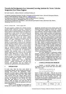
In this part of the second step we compose pre-qualified tools into tool chains. This consists of creating an early TIL design model. Below we give a short overview of TIL, by referring to a simple example model in Figure 1.
Fig. 1. A Simple TIL Model Illustrating the Graphical Syntax
In TIL a tool chain is described in terms of a number of ToolAdapters 1 and the relation between then. A ToolAdapter exposes data and functionality of a tool. The relation between the ToolAdapters is realized as any of the following Channels: a ControlChannel 2 describes a service call, a DataChannel 5 describes data exchange and a TraceChannel 6 describes the creation of trace links. A Sequencer 3 describes sequential control flow; it executes a sequence of services in a defined order. A User 4 is a representative for a real tool chain user. It is used to describe and limit the possible interactions of the real users with the tool chain. Outgoing control channels from the user denote services invoked by the user, incoming control channels to a user denote a notification sent to the user. A Repository 7 provides storage and version management of tool data.
Each ToolAdapter has an associated ToolAdapterMetamodel, which specifies the structure of the data and the signature of the functionality exposed by the tool adapter. An important design decision taken during the specification of the tool adapter is the scope and granularity of the exposed data. This decision depends on the role of the tool within the tool chain. Our experiments on specifying ToolAdapterMetamodels of different granularity can be used as a guideline [7] for creating an adequate tool adapter metamodel. Each DataChannel has an associated model transformation, which resolves structural heterogeneities between the data of the ToolAdapters, which is structured according to the ToolAdapterMetamodels. The source and target metamodels of the model transformation are thus the respective ToolAdapterMetamodels.
4
Analysis of the Composition
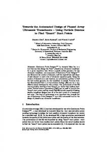
After a tool chain has been modeled in TIL, the risks related to tool integration can be identified from the model. If such a risk is identified, an associated safety goal [5] can be required to be fulfilled for that part of the tool chain. Such a safety goal will point to certain types of mitigating actions that need to be shown to be in place in later steps of our approach. Below we describe three different types of risk associated with tool integration, the analysis of TIL models required to identify these types of risk and the safety goals that can mitigate them. The discussion is based on a small part of a tool chain described in Figure 2. In this example requirements are written by a requirements engineer utilizing the IRQA requirements tool. The requirements are then persisted to a repository before a designer utilizing Enterprise Architect uses them to build an UML model of the end product. After the UML model has been reviewed it is subsequently transferred manually into a Simulink model by a developer. As seen in the minimal TIL model in Figure 2, the tool integration in this example is mainly handled manually. This is not uncommon, even if it is becoming rarer, in state of the practice tool chains.
Fig. 2. Tool Chain of the Running Example Modeled in TIL
4.1
Risk Type 1
Risk Type 1: A developer creates a development artifact. Later during development another developer, who uses information from the previously developed artifact, develops another, more refined artifact. This refined artifact is not complete in regard to or not consistent with the previous artifact, but this can not be detected by the developers. The undetected inconsistencies or incompleteness can lead to hazards in the end product. Detection: The qualification activity to detect whether there is no possibility to detect inconsistencies and incompleteness can be formalized by checking if there are TraceChannels between the ToolAdapters (these provide the ability to create traces). Safety Goal: If this type of risk is detected, it can be mitigated by the safety goal that tracing needs to be enabled by the relevant parts of the tool chain, developers trained in this functionality and processes established to ensure that the functionality is used. The example shown in Figure 2 does not contain any trace channels. After this is detected the analyst can require traceability to be enabled between all ToolAdapters, as shown in Figure 3.
Fig. 3. Traceability Added to the TIL Model
4.2
Risk Type 2
Risk Type 2: A developer studies a development artifact and develops another development artifact by manually transferring information. A tired or untrained developer may make mistakes during this manual transfer. Detection: The qualification activity to detect whether tired or untrained developers can introduce errors during manual transfers of information can be formalized by checking if there are DataChannels between relevant ToolAdapters. The relevant ToolAdapters can be identified based on the type of engineering tools involved. Safety Goal: If this type of risk is detected, it can be mitigated by the safety goal that automatic transformation of development artifacts needs to be enabled by the tool chain, tool chain developers trained in the domain knowledge of the
developers and processes established to ensure that the functionality is used. The example shown in Figure 2 does not contain a DataChannel between Enterprise Architect and Simulink, even though it is tedious work to manually transform models from UML to Simulink. After this is detected the analyst can require a DataChannel to be enabled between these tools, as shown in Figure 4.
Fig. 4. Transformation Added to the TIL Model
4.3
Risk Type 3
Risk Type 3: A project manager retrieves a project report, supposedly extracted from the most recent data on the project status. Unfortunately the new report has been delayed, the manager reads through obsolete information and fails to take mitigating action regarding project issues that may affect safety. Detection: The qualification activity to detect whether the use of obsolete information can not be detected can be formalized by checking if each relevant ToolAdapter has a DataChannel to a Repository/CMSystem (these are, by definition, required to support timestamps or similar [1]). The relevant ToolAdapters can be identified based on which data is used for decision support. Safety Goal: If this type of risk is detected, it can be mitigated by the safety goal that relevant development artifacts need to be time stamped according to a global clock and project managers trained in correctly identifying the time information. For the sake of the example we can assume that a new, complete Simulink model is of interest to project managers. Simulink is not connected to a Repository/CMSystem in the example shown in Figure 2. After this is detected the analyst can require Simulink to be connected to the Repository/CMSystem, as shown in Figure 5. This last model, shown in Figure 5, can be annotated to highlight the required changes in the tool chain, but also with requirements outside the technical domain (such as the training and processes mentioned above). In this way what needs to be supported by the deployed tool chain to mitigate the risks due to tool integration can be communicated and the qualification focused on a more limited part of the development environment.
Fig. 5. Time Information Added to the TIL Model
5
Related Work
Existing standards deal with qualification and certification in different ways, as discussed in [5]. Some standards require tools to be suitable and of a certain quality [3], while some are stricter and require the development of relevant tools to fulfill the same objectives as the development of the products handled by the standard itself [12]. However, the approach of these standards or the related state of the practice discussion is mostly to limit any software qualification effort to engineering tools and their immediate environment. This means that modern safety standards do not address all hazards that occur due to the integration of tools into tool chains in modern development environments. An example is the introduction of an automated transformation of data between two tools. If this is at all dealt with in the context of the current standards, it will most likely be viewed as some kind of error-reducing mechanism that lowers the qualification effort required for the tool that delivers data to the transformation (in the way IEC 61508:2010 views all integration as only positive [4]). However, ideally the transformation itself should also be subject to qualification and its effects on developers identified (if it for instance lowers the possibility for developers to detect errors in output). Apart from the approach to qualify everything in a development environment, only a few proposals for how to approach tool chain qualification exists today ([10] suggests to only qualify the first and the last tools in a tool chain). Little effort has however been spent on identifying the actual implications on safety due to tool integration.
6
Summary and Future Work
In this paper we propose the use of a modeling language for tool chains, TIL, to tailor and analyze tool chains for developing safety-critical embedded systems. This supports a pre-qualification effort of tool chains consisting of pre-qualified tools, aimed at identifying the risks related to tool integration. These risks point out the safety goals that need to be supported by the tool chain after it is deployed to ensure the safety of the end product.
Through this approach the qualification effort is reduced to only those parts relevant to ensure safety. It also allows for a formal way of communicating these parts and the requirements on them, or even automatically generating code for them. These benefits should both increase the confidence in catching safety issues due to software used in the development of safety-critical products and reduce the cost of attaining this confidence. The next steps include: – Extending the annotations of the TIL models to include issues like the granularity of traces, the skill level of operators, etc. – Formalizing additional patterns and providing automated analysis. – Making use of the existing code generation from TIL models. – Performing a case study to compare the result of our automated qualification with that of a manual process and determine the efficiency gain.
Acknowledgement The authors acknowledge partial funding for the work on this paper by the ARTEMIS Project MBAT.
References 1. Matthias Biehl. Tool Integration Language. Technical Report ISRN/KTH/MMK/R-11/16-SE, Royal Institute of Technology (KTH), September 2011. 2. Matthias Biehl. Early Automated Verification of Tool Chain Design. In Proceedings of ICCSA2012, June 2012. 3. CENELEC. BS/EN 50128:2001, railway applications - communications, signalling and processing systems - software for railway control and protection systems, 2001. 4. International Electrotechnical Commission. BS/IEC 61508:2010, functional safety of electrical/electronic/programmable electronic safety-related systems. 5. Asplund et al. Qualifying software tools, a systems approach. In Proceedings of SAFECOMP 2012, In Press, 2012. 6. Biehl et al. A Domain Specific Language for Generating Tool Integration Solutions. In 4th Workshop on Model-Driven Tool & Process Integration at the European Conference on Modelling Foundations and Applications, June 2011. 7. Biehl et al. High-Level Specification and Code Generation for Service-Oriented Tool Adapters. In Proceedings of ICCSA2012, June 2012. 8. Christie et al. Software Process Automation: Interviews, Survey, and Workshop Results. Technical report, SEI, 1997. 9. Conrad et al. Qualifying software tools according to ISO 26262. In Proceedings of MBEES10, February 2010. 10. Hamann et al. ISO 26262 release just ahead - remaining problems and proposals for solutions. In SAE 2011 world congress & exhibition, April 2011. 11. International Organization for Standardization. ISO 26262:2011, road vehicles functional safety, 2011. 12. Special Committee 205 of RTCA. DO-178C, software considerations in airborne systems and equipment certification, 2011. 13. Special Committee 205 of RTCA. DO-330, software tool qualification considerations, 2011.