tion, and certification processes must be involved in the development cycle. Automated ..... of Simulink/Stateflow automotive system designs using a symbolic model checker is proposed in [20]. ..... In ASE, pages 91â102. IEEE Computer ...
Tool Chain to Support Automated Formal Verification of Avionics Simulink Designs? J. Barnat1 and J. Beran2 , L. Brim1 , T. Kratochv´ıla2 , and P. Roˇckai1?? 1) Faculty of Informatics, Masaryk University Brno, Czech Republic, 2) Honeywell International Aerospace Advanced Technology Europe Brno, Czech Republic
Abstract. Embedded systems have become an inevitable part of control systems in many industrial domains including avionics. The nature of this domain traditionally requires the highest possible degree of system availability and integrity. While embedded systems have become extremely complex and they have been continuously replacing legacy mechanical components, the amount of defects of hardware and software has to be kept to absolute minimum to avoid casualties and material damages. Despite the above-mentioned facts, significant improvements are still required in the validation and verification processes accompanying embedded systems development. In this paper we report on integration of a parallel, explicit-state LTL model checker (D IVIN E) and a tool for requirements-based verification of aerospace system components (HiLiTE, a tool implemented and used by Honeywell). HiLiTE and the proposed partial toolchain use MATLAB Simulink/Stateflow as the primary design language. The work has been conducted within the Artemis project industrial Framework for Embedded Systems Tools (iFEST).
1
Introduction
The complexity of embedded systems and of their architecture has been growing rapidly, primarily due to market demand for more functionality. Moreover, more advanced technologies are becoming available and are being combined in new and innovative ways. This complexity growth demands improved tool support. It is becoming impossible to engineer high quality systems in a cost efficient manner without extensive tool support, which is often coming from heterogeneous, disparate set of tools. It is of utmost importance that these tools work well together. The safety-critical nature of systems developed in avionics industry increases otherwise high development cost even more. This is because thorough verification, validation, and certification processes must be involved in the development cycle. Automated ? ??
This work has been partially supported by the Czech Science Foundation grants No. GAP202/11/0312 and GD102/09/H042 and by ARTEMIS-IA iFEST project grant No. 100203. Petr Roˇckai has been partially supported by Red Hat, Inc. and is a holder of Brno PhD Talent financial aid provided by Brno City Municipality
formal verification methods, such as model checking [8], can significantly help lower the cost of verification and validation process. Incorporation of model checking into the development cycle may result into a development process capable of delivering systems at a reasonable cost and the required level of safety [9]. An important lesson learned from the effort spent on verification of avionics systems [4] shows that the major bottleneck preventing successful application of model checking to verification of avionics systems is the scalability of verification tools. While symbolic model checking tools have been successfully applied in model-based development based on Mathworks Simulink [14], their scalability is unfortunately quite limited. One of the factors limiting scalability is the absence of distributed tools: none of the symbolic model checkers can distribute the work among multiple computation nodes [7]. On the other hand, explicit-state model checking has been repeatedly reported to scale well in a distributed-memory environment [21, 5]. Also it is not entirely clear that a symbolic approach is the best possible option for verification of hardware-software co-designed systems. While symbolic methods are more easily applied since they can naturally cope with data-related state space explosion, the explicit-state methods can still be a more efficient [12] alternative. However, some abstraction, ideally automated, is required to deal with data manipulated by the investigated model. In this paper we aim at chaining tools used for development of embedded systems with parallel, explicit-state model checker D IVIN E [2]. This allows for verification of systems against properties specified in Linear Temporal Logic (LTL), a standard formalism for expressing important behavioural properties, cf. Process Specification Language [19].
2 2.1
Tools in the Chain Simulink
Simulink is a model-based design tool widely used in the aerospace industry. It allows design, simulation and code generation for dynamic and embedded systems [14]. A Simulink model is a design of the system built from a set of interconnected blocks. We will leave out continuous blocks (those with real-valued inputs and/or outputs) in this paper and will focus on discrete blocks: without special precautions, model checking in general (and D IVIN E in particular) can only be used with discrete systems. Discrete blocks produce an output at specific points in time, governed by a global discrete clock. Simulink provides libraries of blocks and also allows user to define their own custom blocks. Connected blocks comprise a sub-system and multiple sub-systems are combined to create a hierarchical system model. 2.2
HiLiTE
Honeywell Integrated Lifecycle Tools and Environment (HiLiTE) is a tool used within Honeywell for the requirements-based verification of aerospace systems. HiLiTE has been qualified for use in RTCA DO-178B processes, and has been applied to the verification of thousands of practical Simulink models that are derived from a wide variety of
domains, including flight control algorithms, discrete mode logic, built-in tests, hybrid perimeter controls and many others [3]. HiLiTE provides in-depth semantic analysis of models for design consistency and robustness, as well as automatic generation of certifiable code and of test vectors. 2.3
ForReq
In order to automate the validation and verification of requirements, they need to come in a machine-readable form. Whenever we refer to “formal requirements”, it is implied that these are available in a suitable machine-readable format. Since the vast majority of legacy requirements are written in informal technical language it is necessary to formalize them. For this purpose, we have implemented a prototype of an HiLiTE extension (ForReq: Formalizing Requirements), a special requirements management tool that aims to simplify the task of formalizing requirements. It guides the user in creation of machine readable requirements from scratch or from legacy requirement documents. ForReq provides the user with requirement patterns to ease the formalization process. Requirement patterns are similar to design patterns which are typically used in design tools. A requirement pattern consists of a requirement name and classification, a structured English specification without scope, a pattern intent, temporal logic mappings or other mappings, examples, and relationships. Our requirement patterns are based on a Specification and Pattern System created by Dwyer [10] extended by real-time patterns by Konrad and Cheng [13]. Currently, ForReq is using an improved pattern system adapted to be aligned with aerospace requirements. Once the requirement pattern and the scope is selected it contains so-called propositions (P, Q, R, S, T, and U) which need to be further refined. At this point our approach provides the engineer with the unique feature to assign a design (Simulink model) to the set of requirements. Our method obtains a list of variables from the design, allowing the engineer to select and use the variables in propositions (P, Q, R, ...). This also enables verification of the coverage of inputs and outputs with requirements and allows the tool to report any inputs or outputs that are not covered by at least one of the requirements. Once the requirement is formalized, i.e. the requirement pattern is selected and all propositions are specified with logical formulae containing some model design variables, ForReq executes the D IVIN E model checker and provides it with the assigned design and the temporal logic formula corresponding to the selected requirement pattern. We have developed a transformation from the design model (Simulink) to a form suitable as an input for the D IVIN E model checker. Since every proposition within the temporal logic formulae are logical formulae consisting solely of design variables, the model checker can directly return a confirmation that the requirement is satisfied, or alternatively, a counterexample which demonstrates the behaviour that falsifies the requirement. 2.4
D IVIN E
D IVIN E is a tool for explicit-state LTL model checking and reachability analysis of discrete distributed systems [2]. The distinguishing quality of the tool is its ability to
efficiently exploit the aggregate computing power of multiple network-interconnected multi-core workstations in order to deal with very large verification tasks, beyond the size handled by comparable sequential tools.
3 3.1
Model Checking with D IVIN E Linear Temporal Logic
Model checking is an automated formal verification procedure that takes a behavioral model of a system and decides whether the model satisfies a given property. Properties to be verified by the model-checking procedure vary significantly. Due to the exhaustive statespace search that is behind the model checking procedure, model checkers can formally prove properties such as an absence of a deadlock in a concurrent system, or (un)reachability of a particular system state. However, the real advantage of the technique lies in the ability to check for temporal properties of systems. An example of temporal property that is most often checked with a model checker is a response property, i.e., System will always react by performing action R to every stimulus action S. Linear Temporal Logic (LTL) is often used in combination with explicit-state model checkers to formalize the properties. Formulae of LTL are built from the so-called atomic propositions, boolean-typed expressions evaluated on individual system states, and boolean and temporal operators. The key temporal operators used in LTL are the unary operators F (Future), G (Globally), X (Next) and the binary operator U (Until). Formulae of LTL describe properties of individual system runs. A run is a (possibly infinite) sequence of system states. A run satisfies the LTL formula Fϕ if there is a state in the run (suffix of the run, to be more precise) where ϕ holds. In other words, Fϕ says that ϕ holds true somewhere along the run (in the future of the initial state). Operator G(ϕ) holds for a state on the run if all the following states of the run satisfy ϕ (i.e. ϕ is globally true). Operator X(ϕ) requires ϕ to be valid in the next state. Finally, ϕUψ requires that ϕ holds true, until ψ is satisfied at some state. The LTL formalism allows the user to express many important properties of reactive systems. Examples of some LTL-expressible properties are: Infinite repetition of ϕ, expressed in LTL as GFϕ, inevitable stability of ϕ, expressed as FGϕ, or a sequence of (alternating) occurrences of ϕ and ψ, expressed as ((¬ψ)U(ϕ ∧ (¬ψ)) ∧ F(ψ)). To answer an LTL model checking question, an LTL model checking tool typically employs the automata-theoretic approach, which allows reducing the LTL modelchecking problem to the problem of non-emptiness of a B¨uchi automaton. In particular, the model of a system S is viewed as a finite automaton AS describing all possible behaviours of the system. The property to be checked (LTL formula ϕ) is negated and translated into a B¨uchi automaton A¬ϕ describing all the behaviours violating ϕ. In order to check whether the system violates ϕ, a synchronous product AS × A¬ϕ of AS and A¬ϕ is constructed describing all those behaviours of the system that violate ϕ, i.e. L(AS × A¬ϕ )=L(AS ) ∩ L(A¬ϕ ). The automata AS , A¬ϕ , and AS × A¬ϕ are referred to as the system, property, and product automaton, respectively. System S satisfies formula ϕ if and only if the language of the product automaton is empty, which is if and only if
there is no reachable accepting cycle in the underlying graph of the product automaton. The LTL model checking problem is thus reduced to the problem of the detection of an accepting cycle in the product automaton graph. 3.2
Common Explicit-State Model Interface
An important part of the workload of the model-checking tool lies in the interpretation of the model under verification. The interpretation requires the model checker to compute successors of individual states of the model. To reduce this load, D IVIN E offers an option to process the input models specified in DVE – D IVIN E native modelling language – either as a text file, or as a binary file that results from compilation of the text file into a native binary code (in a form of dynamically loaded library) of the target hardware platform. It should be understood that the binary interface allows D IVIN E to load and use binary models other than those resulting from compilation of native DVE modelling language, as long as they provide the mandatory portions of the binary interface. Henceforward, we refer to the binary interface as to “Common Explicit-State Model Interface” (CESMI for short). CESMI can be used to provide D IVIN E with the model to be verified at two different stages of the automata-based approach to LTL model checking. First, CESMI can be used to access the graph of the product B¨uchi automaton AS × A¬ϕ . Note that the graph of an automaton can be given either explictly by enumerating all its states, transitions, etc., or implicitly by providing functions to compute the explicit representation. CESMI assumes the implicit way of definition of the graph, therefore, it requires the following functions to be defined in the binary file: – initial state, a nullary function (i.e. a constant) – successors, a function from states to sets of states – is accepting and is goal: unary boolean functions, classifying states as accepting and goal, respectively The second option is to provide D IVIN E with an implicit definition of the model graph only, i.e. graph of automaton AS . D IVIN E can compute the property automaton AS × A¬ϕ . internally from a given LTL formula ϕ and system automaton AS given though the CESMI-compliant input file. However, to do so, D IVIN E requires functions to evaluate atomic propositions used in the input LTL formula at individual states of the system automaton. Therefore, the basic CESMI interface has to be extended with functions to evaluate all atomic propositions used in the formula. – AP a unary boolean function, classifying states based on validity of atomic proposition a Should the latter case be used for LTL verification, the combine command of D IVIN E must be issued on CESMI-specified model file and LTL formula, in order to produce a binary file with the implicit (CESMI) definition of the target product automaton. An important fact to be understood is that parallel distributed-memory model checking capabilities as offered by D IVIN E are independent of the actual model described through the CESMI interface. Once the model is given via CESMI, parameters of parallel and distributed-memory processing are simply part of particular D IVIN E invocation.
4
The HiLiTE/D IVIN E interface
The main contribution of the proposed toolchain is a module that allows application of parallel explicit-state LTL model checking to data-flow oriented designs. Even though there is a certain amount of variance between various data-flow programming languages, they share many common traits. Data-flow systems are typically build up from blocks, which are connected using data connections. All the blocks typically execute in parallel, but unlike the standard concurrent software that is typically subject to model checking, this execution is synchronous across the whole system: all computation is done strictly in a lockstep manner. Like with protocol design, the dataflow program often has no clear single line of execution: the systems are often reactive in nature. This naturally gives rise to the need for temporal properties. 4.1
Explicit-state Interpretation of Data-flow Programs
In order to verify a data-flow program by means of model checking, we have to define an executable model of it. In our case, the primary language of interest is Matlab Simulink, which is widely used in design of avionic systems. For getting an executable model from the Matlab Simulink model, we opted for a two-level approach. First, we translate the Simulink model into a specific intermediate language of ours, and then we translate the intermediate representation into the form that is accepted by the model checker. The intermediate langugage was designed to be suitable as a target language also for other data-flow programming languages. The intermediate language is in fact a simple EDSL (embedded domain-specific programming language) for describing synchronous data circuits in C++. Programs in this domain specific language are produced by a dedicated compiler that will process Simulink designs.1 The produced EDSL code can then be compiled using a standard C++ compiler, producing a shared object conforming to the CESMI specification (see Section 3.2). This shared object can then be directly used as a verification subject, if we are interested in simple safety properties like presence of deadlocks. However, in the context of dataflow programs, this is not a very interesting question: more general safety and liveness properties can be expressed using LTL (see also Section 3.1). To refer to “atomic” properties of the design in the specification of properties, the design needs to provide so-called “atomic propositions”. These are statements about individual system states, and are directly expressed in the EDSL translation of the model: in our case, the Simulink compiler is responsible for providing their definitions from a high level description. When these atomic propositions are specified, this is enough for the automated process of translating the LTL specification (which can refer to these atomic propositions, and derive). The intermediate language provides support for creating blocks and connections between them. There are two main types of blocks: atomic and composite: implementation 1
While the compiler which translates Simulink designs into our data-flow EDSL is proprietary (part of the ForReq extension of HiLiTE), the implementation of the intermediate EDSL itself is part of the D IVIN E tool which is available for public download, including the source code, from http://divine.fi.muni.cz.
template< typename T > struct Sum : Value< T > { InSet< T, 4 > in; virtual T get() { T acc = 0; typename InSet< T, 4 >::iterator i; for ( i = in.begin(); i != in.end(); ++i ) acc += (*i)->get(); return acc; } };
Fig. 1. The data-flow EDSL in C++. An example (atomic) block with 4 inputs and a single output, implementing summation.
of atomic blocks needs to be done in terms of C++ code implementing the operation. An example of atomic block would be summation, product, minimum and the like: the source code for a summation atomic block is shown in Figure 1. Atomic blocks implement basic operations, and as such provide building blocks for composite blocks, which correspond to actual data-flow programs, or sub-programs. Since composite blocks can be naturally used as building blocks for other, more complex composite blocks, modular designs are easily expressible. In the Simulink translation, composite blocks are the natural counterpart of sub-systems as well as the entire system design. The input program consists of a number of blocks with input and output ports and connections. The computation of the overall design is controlled by a global discrete clock. Every tick of the global clock triggers sampling on the system inputs (that are connected to the environment) and re-computation of all port values in the system based on data dependencies (represented by block connections). While CTL is the common language for specifying synchronous systems, LTL is more commonly supported by model checkers geared towards asynchronous parallel systems, mainly software. Moreover, LTL model checkers more commonly use an explicit-state representation, which allows for parallel distributed-memory procesing. Since the application of parallel model checker was one of our primary goals, we needed to adapt the synchronous data-flow system for the purposes of explicit-state model checking. To this end, we needed to build an implicit representation of the state transition system corresponding to the behaviours encoded by the data-flow program. We have so far only described data-flow programs on a very high level. To describe the transition system derived from a data-flow program, we need to look at the semantics of blocks in more detail. While it is an important feature of data-flow programming that most blocks contain no explicit memory – they operate solely on their inputs in a functional way – this is not a strict requirement. In fact, many designs require memoryful blocks: in the Simulink parlance, these are called delay and Stateflow state machine blocks. As for the delay block, the effect of the memory contained in a block is the
introduction of a delay on the “signal” when it passes through a block. It is the state of this memory that introduces statefulness to data-flow programming (a memory-free data-flow program is stateless, and traditional LTL model checking cannot be applied, although it can still be meaningfully combined with a stateful environment – more on this in Section 4.2). Note that in current implementation our toolchain has no support for Stateflow blocks yet.
Requirements
LTL
D IVIN E combine
CESMI
CESMI
D IVIN E
HiLiTE ForReq Design (Simulink)
EDSL
G++
Counter-example
VALID
Fig. 2. The verification workflow based on the proposed toolchain.
4.2
Environment
A reactive system, such as a data-flow program, is by definition an open system (it does not specify complete behaviours): the system reacts to stimuli from the environment: the environment comprises everything relevant that surrounds the reactive system in question. It could include other components of the entire system like sensors, actuators, other control units, and external factors such as weather, people and the like. In order to verify properties of the reactive system, we need to simulate this surrounding environment and its effects on the reactive system. To this end, we create a simplified model of the environment and connect the inputs and outputs of the reactive data-flow program to the environment. To make a sensible environment model possible, we allow non-determinism in the actions originating in it: at any instant, a temperature rise or a drop might happen (although not both at the same time). When the design and the environment model are connected, we obtain a closed system, and as such can be subject to model checking. However, the requirement to have a sensible environment can be an impediment to the verification process: it is another step that needs attention and manual work. Fortunately, for many purposes, the environment does not need to be very sophisticated, or even very sensible. In fact, a rather liberal environment puts more stringent requirements on the designed system itself. Additionally, it is easily possible to automatically generate an environment that is liberal in the extreme: one where anything might happen (we will say that this type of environment is universal). Such an environment is good enough surprisingly often, and can reveal overly optimistic assumptions the designer is making about the actual environment of the system.
4.3
Branching explosion
Nevertheless, an universal environment has one major drawback in the presence of numeric inputs in the system: the environment actions corresponding to these inputs are of the form “value of input X has changed to Y ”, and in an universal environment, such an action will exist for each permissible Y . For inputs with large domains, this has the effect of creating extremely many actions, and consequently extremely many transitions in the resulting system. This in turn has disastrous effects on tractability of the model checking problem, since even simple systems can have millions of transitions between any their states. Since all model checking algorithms need to explore each transition to remain correct (unless they can prove a given transition to be redundant, an option that we will explore in the following section), this means that to make model checking practical in these situations, we need to limit the number of transitions (environment actions) that can happen. One solution to this problem is to place simple constraints on the universal environment, without compromising our ability to generate such environments automatically. The universal environment is stateless: it remembers nothing and can do anything at any time. Especially when it comes to modelling variable quantities of the real world, this is overly pessimistic. If the environment is made stateful, it can remember the current values of the variables it models, and the limits can be in form “value X can change by at most Y in a single clock tick”. Such limits can bring down the number of actions available at any given instant considerably. Unfortunately, this construction has the dual problem: now each environment variable with domain size n will cause existence of n distinct states, which again precludes efficient model checking. An approach akin to region construction could be used to address this latter problem though (this is a subject of future work; we expect this approach to be simpler than using a fully symbolic representation).
4.4
Data abstraction
A more common, but more involved approach to deal with big domains is symbolic (abstract) representation. Instead of working with single values, the model checker manipulates entire sets of values. With this approach, the environment simply sets all its variables to carry their full domain as the symbolic value, which exactly corresponds to the notion of “any value”. Then, it is the job of the model checker to refine the various sets adaptively: whenever a decision that depends on a variable value is done, and the answer will be different for different values in the current set, this set needs to be split (according to the predicate) and each part propagated along the control flow decision which has observed the respective part of the set. Since control flow decisions are comparatively rare in primarily data-flow based programs, this technique is likely to work very well. Nevertheless, efficient implementation of sets with the required operations is hard and laborious. In the domain of hardware design, application of BDDs (binary decision diagrams) in this role was a significant breakthrough. On the other hand, SAT and SMT solvers have been employed in software-oriented tools with some success, especially in the context of bounded model checking.
Nevertheless, none of these approaches is fully suitable for verification of generic, high-level data-flow programs. Arithmetic operations pose a challenge for BDD and SAT based representations, which are fundamentally bit-oriented. On the other hand SMT solvers are hard to implement, and scarce. Fortunately, in many cases (especially in our case of data-flow oriented programming), a relatively simple static heuristic can be used to compute a set of abstract partitions that cover all behaviours of the program, by set-based, or rather symbolic, back-propagation. Using this partitioning, we can generate an abstract environment that will be substantially simpler. Additionally, we can entirely avoid set-based arithmetic in model checking, which would be required in a fully symbolic approach: instead, the abstract environment can directly use single concrete representatives from each abstract set of inputs, and the program can be interpreted concretely as usual.
5
Related Work
There are many types of tools for automated formal verification, each with their own strengths and weaknesses. Explicit state model checkers such as SPIN or D IVIN E enumerate and store individual states. Implicit state (symbolic) model checkers such as NuSMV store sets of states using a compact representation (such as Binary Decision Diagrams). Alternatively, bounded model checkers such as CBMC use boolean formulae for symbolic representation and employ SAT solvers. Satisfiability modulo theories (SMT) model checkers such as SAL and Prover use a form of induction to reason about models containing real numbers and unbounded arrays. Their properties need to be written in such a way that they can be proven by induction over an unfolding of the state transition relationship. For this reason, they tend to be more difficult to use than explicit and symbolic state model checkers. Tools like SPIN, D IVIN E, NuSMV, or SMC (a statistical model checker extension to UPPAAL) are not tightly integrated with a specific software design tool and can be used as stand-alone tools and possess a tool-specific input language. Application of the tool to models in “non-native” language usually requires either manual re-modelling of the system or, preferably, an automated translation between the two languages. There is extensive work on translating Simulink/Stateflow models to modelling languages of specific model checkers. We will mention only some of those that we think are the most relevant. A translation into the native language of the symbolic model checker NuSMV is presented in [1]. The paper [11] suggests an analysis of Simulink models using the SCADE design verifier in the particular setting of system safety analysis. Another translation, this time from Stateflow to Lustre is described in [18]. Both share the interpretation of Simulink and Stateflow as a synchronous language, as mandated by the use of Lustre as the target language for the translations. Invariance checking of Simulink/Stateflow automotive system designs using a symbolic model checker is proposed in [20]. A first attempt to validate Stateflow designs using SPIN is presented in[16] (the described tool is however not publicly available). More recently a team at Rockwell Collins has built a set of tools [22, 9, 15] that translate Simulink models into languages of several formal analysis tools, allowing direct analysis of Simulink models using model checkers and theorem provers. Among
the tools considered are symbolic model checkers, bounded model checkers, model checkers using satisfiability modulo theories and theorem provers. Unlike the above-mentioned tools, tools like SDL tool Telelogic TAU, the Statemate ModelChecker, SCADE Design Verifier [17], and the Simulink Design Verifier (an optional component of the Matlab Simulink tool set based on SAT technology) are tightly integrated with the design tool that they belong to. The design tools are typically domain specific. The Telelogic TAU tool, for instance, enjoys widespread popularity in telecommunications while Matlab Simulink is a de-facto standard for software design in automotive system engineering. Our approach differs from the above-mentioned in using a parallel explicit-state LTL model checker to directly handle Simulink models and employing distributed memory to attack the state explosion problem. We are not aware of any other work with similar ambitions.
6
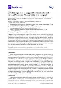
Use Case – Honeywell’s Voter Core
The environment is automatically generated from a Simulink model. In each discrete time step, the environment ensures that the input blocks can assume any value within a certain range. For each input block the user specifies its permissible input range. Moreover the range can be further automatically reduced, as HiLiTE refines the actual range of each input and output of each block, using both forward and backward propagation of ranges of incident blocks using their semantics, through calculation of inverse functions for the analyzed blocks [3]. 6.1
Voter Core Specification
Voter Core is the sub-system of the common avionics triplex sensor voter described in the paper [1]. However the Voter Core sub-system is not defined in the paper; therefore our engineer had to design it from scratch. The design shown in Figure 3 was given to the engineer with the task to design the highlighted Voter Core sub-system conforming to the following informal requirements: 1. If signal delta > 1 or signal is not valid, signal mismatch shall hold. 2. If signal mismatch held for 3 time units, permanent mismatch shall hold. 3. Once permanent mismatch holds it shall hold forever. The picture in Figure 4 shows the Voter Core sub-system as designed by the engineer. 6.2
Formalizing Requirements
We will demonstrate how the ForReq tool guides the user to formalize requirements, by walking through the process of formalization of the last requirement mentioned above. The user always starts with a scope and a specification and derives the complete requirement pattern step by step:
signals
(u , 0 , L ) [ 1 ] 1
sensorData
+ n
Dmx
2
1
3
2
deMux
outputData
d 1
divide
3 mux
magnitudeThld
signal _mismatch
signal _delta
n /d
− sum
Mux
permanent _mismatch
signal _valid
Dmx
1
2
2
3
(a , 0 , L ) [ 3 ]
outputData SensDataOK
Mux
switch filterOutputData
deMux 3
Voter Core Sub −system
Error
1 1
3
2
deMux 1
3
Mux
(b , 0 , L ) [ 2 ]
1 /z
1 /z
simpleDelay {IC =0}
Dmx
1
2
2
3
and 1
1
or
and
Dmx
2 3
deMux 2
and 3
deMux 4
1
simpleDelay {IC =0}
Mux
mux 4
3 mux 1
valids
(a ) [ 3 ]
1
2
Dmx
(a ) [ 1 ]
ground
and 2 mux 3
3
not 1 and 5
1 1 Dmx
2
Mux
2
not 2
3
not
3
and 4 deMux 5
or 1
mux 2
twoValidMisc
(a ) [ 4 ]
outputValid
(a ) [ 2 ]
1 /z simpleDelay {IC =0}
2
uint 32 1 Dmx
typecast
2
uint 32 typecast 1
3
uint 32
deMux 6
typecast 2
+ a
+
a>=b +
C
b
and 6
sum 1 const greaterEq c=uint 32(1)
Fig. 3. The complete Voter subsystem, showing the context for the Voter Core component. signal _delta
(a, , L) [1]
a a>b
C constant
signal _mismatch (b) [1]
b
greaterThan and
c=uint32(1)
signal _valid
uint 32 typecast
(b, , L) [2] not
c=uint32(3)
1/z + sum
C constant 3
+ simpleDelay {IC =0}
Min
a a>=b
C
c=uint32(0)
permanent _mismatch (b) [2]
b
constant 8
greaterEq switch
min
Fig. 4. The proposed design of the Voter Core.
– scope, specification. The scope of the requirement is after the “permanent mismatch holds” atomic proposition is valid. The partially formalized sentence will be: – After Q, (order ∨ occurrence). The user chooses the type of requirement pattern, occurence in this case. After that user chooses the universal requirement pattern: – After Q, it is always the case that P holds. ForReq then guides the user to assign the propositions Q and P with the logical formula with atomic propositions as variables that are directly mapped to Simulink model variables. In our use case the propositions Q = P = permanent mismatch are valid only if permanent mismatch signal is true. The engineer eventually arrives at the following formalized requirements: 1. Globally, it is always the case that if (signal delta > 1 ∨¬signal valid) holds, then (signal mismatch) holds immediately. 2. Globally, it is always the case that if (signal mismatch) holds for at least 3 time unit(s), then (permanent mismatch) holds immediately.
3. After (permanent mismatch), it is always the case that (permanent mismatch) holds. And the corresponding (automatically generated) LTL formulae: 1. G((signal delta > 1 ∨¬signal valid) → (signal mismatch)) 2. G(G