I.J. Intelligent Systems and Applications, 2014, 12, 17-26 Published Online November 2014 in MECS (http://www.mecs-press.org/) DOI: 10.5815/ijisa.2014.12.03
Tracking Power Photovoltaic System using Artificial Neural Network Control Strategy M.T. Makhloufi LEA Lab. Electronics department, Faculty of Technology, Batna University, Chahid M.ohamed Belhadi Boukhlouf Road, Batna, Algeria E-mail:
[email protected]
M.S. Khireddine, Y. Abdessemed, A. Boutarfa LRP & LEA Labs. Electronics department, Faculty of Technology, Batna University, Chahid M.ohamed Belhadi Boukhlouf Road, Batna, Algeria E-mail:
[email protected],
[email protected],
[email protected]
Abstract—Photovoltaic generation is the technique which uses photovoltaic cell to convert solar energy to electric energy. Nowadays, PV generation is developing increasingly fast as a renewable energy source. However, the disadvantage is that PV generation is intermittent because it depends considerably on weather conditions. This paper proposes an intelligent control method for the maximum power point tracking (MPPT) of a photovoltaic system under variable temperature and solar irradiation conditions. In this paper, a simulation study of the maximum power point tracking (MPPT) for a photovoltaic system using an artificial neural network is presented. The system simulation is elaborated by combining the models established of solar PV module and a DC/DC Boost converter. Finally performance comparison between artificial neural network controller and Perturb and Observe method has been carried out which has shown the effectiveness of artificial neural networks controller to draw much energy and fast response against change in working conditions. Index Terms—Solar Energy, Photovoltaic, MPPT, P&O, Boost Converter, Artificial Neural Network
I. INTRODUCTION Significant progress has been made over the last few years in the research and development of renewable energy systems such as wind, sea wave and solar energy systems. Among these resources, solar energy is considered nowadays as one of the most reliable, daily available, and environment friendly renewable energy source [1-2]. However, solar energy systems generally suffer from their low efficiencies and high costs [3]. In order to overcome these drawbacks, maximum power should be extracted from the PV panel using MPPT techniques to optimize the efficiency of overall PV system. MPPT is a real-time control scheme applied to the PV power converter in order to extract the maximum power possible from the PV panel [12]. The MPPT working principle is based on the maximum power transfer theory. The power delivered from the source to the load is maximized when the input
Copyright © 2014 MECS
resistance seen by the source matches the source resistance. Therefore, in order to transfer maximum power from the panel to the load the internal resistance of the panel has to match the resistance seen by the PV panel. For a fixed load, the equivalent resistance seen by the panel can be adjusted by changing the power converter duty cycle [4]. The literature is rich with various MPPT techniques based on different topologies and with varying complexity, cost, and overall produced efficiency [13]. The Hill Climbing (HC) and the Perturb and Observe (P&O) are the most known and commercially used techniques [5-7]. Other modified methods such as the incremental Conductance (INC) technique, the neural network (ANN) technique, and fuzzy logic controller technique, have been also reported to improve the performance of these techniques. In HC-MPPT technique, the duty cycle is directly incremented or decremented in fixed steps depending on the panel voltage and power values until the maximum power point (MPP) is reached. The P&O technique shares the same HC concept of operation, but with an additional PI control loop. In the P&O, the converter input reference voltage is the perturbed variable and the duty cycle is computed through an additional PI control loop [16]. The additional control loop results in an increase in the P&O efficiency, as the system demonstrates a faster dynamic performance and better-regulated PV output voltage compared to HC. The P&O method is commonly used because of its simplicity and ease of implementation [5-6]. Furthermore, P&O (with a small step size) in nominal conditions can have MPPT efficiencies mostly the same like other complex techniques, and still easier implementation. However, the drawback of this technique is that the operating point of the PV array oscillates around the MPP. Therefore, the power loss may increase. Furthermore, when the sun insolation changes rapidly, the P&O method probably fails to track the MPP. Another possible disadvantage is that the MPPT may not be able to locate the MPP as the amount of sunlight decreases, because the PV curve flattens out [5]. Recently intelligent based control schemes MPPT have been introduced. I.J. Intelligent Systems and Applications, 2014, 12, 17-26
18
Tracking Power Photovoltaic System using Artificial Neural Network Control Strategy
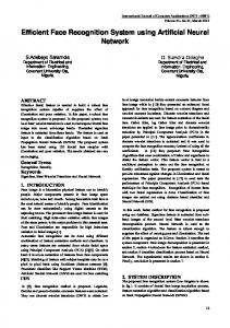
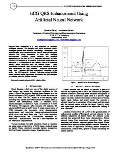
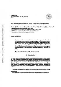
In this paper, an intelligent control technique using artificial neural network control is associated to an MPPT controller in order to improve energy conversion efficiency. The simulation can generate two different solutions for the control of converter system; one is P&O controller and the other one is ANN controller. The circuit diagram of the energy conversion system is shown in Fig.1. The system consists of photovoltaic panel, a DC/DC boost converter, a control unit and a resistive load. The first stage of the system is solar panel. The I-V characteristic of a panel depends on the temperature and solar irradiance. The three most important characteristics of PV panel are the short circuit current, open circuit voltage and the MPP which is a function of panel temperature and solar irradiance. The power stage is the well known Boost converter witch duty cycle is regularly adjusted to track the maximum power point that can be delivered by the PV panel. The proposed MPP tracker, which is based on artificial neural networks control, has the objective to draw as much power as possible from the PV module by adjusting continuously the duty cycle of the DC/DC converter. This point corresponds to the maximum power point (MPP) on the PV curve.
I Rs
I ph
Load Duty cycle
I I ph I s (e
Fig. 1. Schematic diagram of the proposed power conversion PV array
The main content of this paper is organized into several sections. Section two is dedicated to the study of the characteristics of solar panels. Section three is devoted to the study of the maximum power point tracking (MPPT) and section four discusses the modeling of DC/DC converters. Section five presents the different MPPT algorithms (P & O algorithm and ANN algorithm) to make a comparison between these two algorithms. Section six is dedicated to the simulation of the two methods (P & O and ANN). Finally, a general conclusion finished the paper.
q (V IRs ) AkT
1)
V IRs Rsh
(1)
where, Iph is photocurrent; Is is diode saturation current; q is coulomb constant (1.602e-19C); k is Boltzman‘s constant (1.381e-23 J/K); T is cell temperature (K); A is P-N junction ideality factor; Rs and Rsh are intrinsic series resistances. Photocurrent is the function of solar radiation and cell temperature described as
I ph ,ref CT (T Tref )
(2)
where, S is the real solar radiation (W/m2); Sref , Tref , Iph,ref is the solar radiation, cell absolute temperature, photocurrent in standard test conditions respectively; CT is the temperature coefficient (A/K). Diode saturation current varies with the cell temperature
ANN MPP tracker
Ipv
V
The mathematic relationship for the current and voltage in the single-diode equivalent circuit can be described as
Vpv
T
Rsh
Fig. 2. Single-diode mathematic model of a PV cell
S I ph S ref
ǿ
D
_
Boost Converter
Pv module
+
I s I s ,ref
T Tref
3
qEg 1
1
Ak Tref T e
(3)
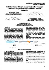
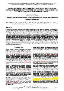
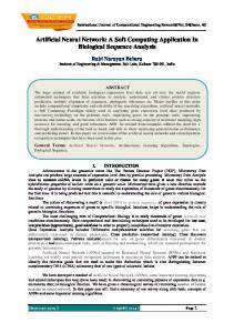
where, Is,ref is the diode saturation current in standard test conditions;Eg is the band-gap energy of the cell semiconductor (eV),depending on the cell material. When PV cells are arranged together in series and parallel to form arrays. These cells are usually considered to have the same characteristics. The equivalent circuit of PV array can be described as Fig.3.
NP NP Iph
II. PV ARRAY
NS
I
NS R NP s NS R NP sh
V _
Photovoltaic cell is the most basic generation part in PV system. Single-diode mathematic model is applicable to simulate silicon photovoltaic cells, which consists of a photocurrent source Iph, a nonlinear diode, internal resistances Rs and Rsh, as shown in Fig.2.
is:
Copyright © 2014 MECS
I.J. Intelligent Systems and Applications, 2014, 12, 17-26
Fig. 3. Single-diode mathematic model of a PV array
The relationship of the voltage and current in PV array
Tracking Power Photovoltaic System using Artificial Neural Network Control Strategy
I N P I ph N P I S (e
q V IRs ( ) AkT N S N P
1)
N P V IRs ( ) Rsh N S N P
(4)
19
We have used the MATLAB/Simulink software in order to implement the model of the PV array, as shown in Fig. 4.
Where, NS and NP are cell numbers of the series and parallel cells respectively.
Fig. 4. Simulink model of the solar PV module
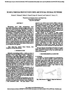
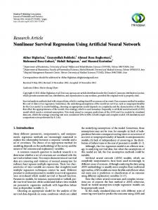
Considering different temperatures and solar irradiations, the simulated output characteristics of the PV array are depicted in Fig. 5 and Fig.6.
S 1000W m2 T 300 K
T 300 K
T 350 K
S 1000W m2
T 400 K
S 500W m 2 S 200W m 2
S 1000W m2
T 300 K T 350 K
T 300 K S 1000W m2
T 400 K
S 500W m 2
S 200W m 2 Fig. 6. Characteristic curves of the PV array with different cell temperatures.
Fig. 5. Characteristic curves of the PV array with different solar irradiations
Copyright © 2014 MECS
As shown in Fig.4 and Fig.5, the PV array has nonlinear voltage-current characteristics, and there is only I.J. Intelligent Systems and Applications, 2014, 12, 17-26
20
Tracking Power Photovoltaic System using Artificial Neural Network Control Strategy
one unique operating point, the MPP, for a PV generation system with a maximum output power under a particular environmental condition.
III. MAXIMUM POWER POINT TRACKING A dynamic tracking method is necessary to extract the maximum power from the PV cells [3]. Many researches has been developed concerning the different algorithms for the maximum power point tracking (MPPT) considering the variations of the system parameters and/or weather changes, such as perturb and observe method, open and short circuit method, incremental conductance algorithm, fuzzy logic and artificial neural network. The block diagram in Fig.2 presents a PV generator with MPPT [5]. The load or the battery can be charged from a PV panel using a MPPT circuit with a specific controller to track the peak power generated by the PV panel. Other protection devices can be added. The control circuit takes voltage and current feedback from the battery, and generates the duty cycle D. This latter defines the output voltage of the Boost converter. Many MPTT control techniques have been conceived for this purpose these last decades [10]. They can be classified as: Voltage feedback based methods which compare the PV operating voltage with a reference voltage in order to generate the PWM control signal of the DC/DC converter [8]. Current feedback based methods which use the PV module short circuit current as a feedback in order to estimate the optimal current corresponding to the maximum power. Power based methods which are based on iterative algorithms to track continuously the MPP through the current and voltage measurement of the PV module. In this category, one of the most successful used method is perturbation and observation (P&O) technique.
IV. DC/DC CONVERTER MODELLING Fig.7 shows the electrical circuit of a boost converter. The power switch ‗S‘ is used to modulate the energy transfer from the input source to the load by varying the duty cycle D [6]. The relationship between input and output voltages of boost converter operating at steady state condition is given by:
V0 1 Vi 1 D
(5)
Fig. 7. Boost converter circuit
The control strategy lies in the manipulation of the duty cycle of the switch which causes the voltage change. When the switch is closed and the inductor is charged by the source through the switch. The charging current is exponential in nature but for simplicity is assumed to be linearly varying. The diode restricts the flow of current from the source to the load and the demand of the load is met by the discharging of the capacitor. When the switch is open and the diode is forward biased. The inductor now discharges and together with the source charges the capacitor and meets the load demands. The load current variation is very small and in many cases is assumed constant throughout the operation. The MATLAB/Simulink model of the basic boost converter is shown in Fig.8.
Fig. 8. Simulink model of boost converter.
V. DIFFERENT ALGORITHM MPPT It is necessary to constantly track the MPP of a solar panel. For the past years, research has focused on various Copyright © 2014 MECS
MPP control algorithms to draw the maximum power of the solar array. In this section, the effectiveness of two different control algorithms are thoroughly investigated using a numerical simulation. I.J. Intelligent Systems and Applications, 2014, 12, 17-26
Tracking Power Photovoltaic System using Artificial Neural Network Control Strategy
21
A. P&O controller method The P&O algorithm is the most commonly used in PV systems applications due to its ease of implementation and simplicity. It is an iterative method for obtaining the MPP. Whereas, it measures a PV module current and voltage, then perturbs the operating point of a PV module to determine the change direction. Fig.9 shows the flow chart of the classical P&O algorithm. The P&O algorithm has been broadly used because of its practical implementation. The MPP tracker operates by periodically incrementing or decrementing the solar panel voltage, current or the duty cycle comparing to the PV output power with that of the previous perturbation cycle. If a given perturbation leads to increase (or decrease) the output power of the PV, the successive perturbation is generated in the same (or opposite) direction, on Fig.10. We consider that the maximum power point (MPP) is Xm. If the operating point Xi is on the left of MPP, the duty cycle must be decreased until the MPP is reached. If the operating point is on the right of the MPP, the duty cycle is increased to reach the MPP [8].
Fig. 9. Flow chart of the classical P&O algorithm
Fig. 10. Simulink model for P&O Alghorithm
The obtained simulation results for different tests using the P&O algorithm are presented and compared to those obtained with the artificial neural network (ANN) MPPT controller in section 6. B. Artificial Neural Network controller method The MPPT strategy proposed here consists of a combination of an artificial neural network and the MPPT technique in order to implement of the duty cycle regulator. When solar irradiation changes slowly, the system controls the DC-DC converter using the P&O, and the neural network learns simultaneously the MPP found Copyright © 2014 MECS
by the P&O. However if the solar radiation varies too rapidly, the neural network controller tracks the MPP rapidly and adjusts the duty cycle of the DC-DC converter. Neural networks usually require independent and identically distributed samples to ensure successful on-line learning. Here, however, similar training samples are used by the artificial neural network [14-15]. To deal with these training samples, we have used an MLP [8-9] in order to ensure fast and correct learning. The main idea is that the neural network learns each sample online because it is difficult to store all learning samples in small devices. In Fig. 11, the ANN learning technique [11] is a memorybased one and allows estimating at any instant the I.J. Intelligent Systems and Applications, 2014, 12, 17-26
22
Tracking Power Photovoltaic System using Artificial Neural Network Control Strategy
required optimal duty cycle ‗D‘. Even with sparse data in a multidimensional measurement space, the algorithm provides smooth transitions from one estimated value of D to another. The ANN consists of an input layer (Ppv), a pattern layer, a summation layer an output layer. The output of the ANN is the duty cycle D(x) as follow:
same as the last V. If not, the next change in voltage should be negative P&O achieves the function of an MPPT [8] easily, but it cannot track MPP rapidly when solar radiation changes quickly. In order to eliminate this drawback, our MPP technique utilizes an ANN to achieve learning and maximum power point tracking. The MPP tracker operates by periodically incrementing or decrementing the estimated solar panel voltage Vpv. If a perturbation occurs on the PV output, then the subsequent perturbation is generated in the opposite direction. The weights of the neurons are changed subsequently to the presence and severity of a perturbation. They are maintained constants in stable working conditions.
Fig. 11. The Simulink used artificial neural network model
Fig.13. Sign of dP/dV at different positions on the power Characteristic of a PV module.
Fig .12. Training error using the neural network for learning, the obtained error is very small about 10.0e-25
The MPPT technique proposed differs from other techniques in that the duty cycle of the switching of the DC/DC boost converter is optimally calculated on-line. The algorithm of the three-point weights comparison is run periodically by perturbing the solar array terminal voltage and comparing the PV output power on three points of the P-V curve. The three points are the current operation point (A), a point B, perturbed from point A, and a point C, with doubly perturbed in the opposite direction from point B. Fig.13 depicts the three possible cases. In these cases, for the points A and B, if the power corresponding to the point B is greater than or equal to that of point A, the status is assigned a positive weighting. Otherwise, the status is assigned a negative weighting. Amongst the three measured points, if two are positively weighted, the duty cycle of the converter should be increased. On the contrary, when two are negatively weighted, the duty cycle of the converter should be decreased. In the other cases with one positive and one negative weighting, the MPP is reached or the solar radiation has changed rapidly and the duty cycle must not be changed. Fig.13 shows the idea of the MPP detection algorithm. By monitoring voltage V and current I, the P&O algorithm determines whether generated power has increased. If so, the next change in voltage should be the Copyright © 2014 MECS
VI. SIMULATION RESULTS Fig.14 shows the overall simulation circuit under MATLAB/Simulink In order to validate the on-line learning ANN, many simulations tests have been implemented.
Fig. 14. Simulink model for ANN Alghorithm
A. Operation in standard environmental conditions The Figs. 15, 16 and 17 below allow us to visualize the output PV panel current, voltage and power using the fuzzy controllers in standard atmospheric conditions (1000W/m2, 25°C).
I.J. Intelligent Systems and Applications, 2014, 12, 17-26
Tracking Power Photovoltaic System using Artificial Neural Network Control Strategy
Vout 120
25
100
20
80 Voltage(V)
Current(A)
Ipv 30
15
60
10
40
5
20
0
0
0.01
0.02
0.03
0.04
0.05 0.06 Time(sec)
0.07
0.08
0.09
0
0.1
0
0.01
0.02
0.03
0.04
0.05 0.06 Time(sec)
0.07
0.08
0.09
0.1
Fig. 19. The Boost converter output voltage with P&O controller
Fig.15. The output PV panel current
Pout
Vpv 100
1800
90
1600
80
1400
70
1200 Power(W)
60
Voltage(V)
23
50
1000 800
40
600
30
400
20
200
10 0
0
0.01
0.02
0.03
0.04
0.05 0.06 Time(sec)
0.07
0.08
0.09
0
0.1
0
0.01
0.02
0.03
0.04
0.05 0.06 Time(sec)
0.07
0.08
0.09
0.1
Fig. 20. The Boost converter output current with P&O controller
Fig.16. The output PV panel voltage
Iout
Ppv
16
2000 1800
14
1600
12 10
1200
Current(A)
Power(W)
1400
1000 800
8 6
600
4 400
2
200 0
0
0.01
0.02
0.03
0.04
0.05 0.06 Time(sec)
0.07
0.08
0.09
0
0.1
0
0.01
0.02
0.03
0.04
0.05 0.06 Time(sec)
0.07
0.08
0.09
0.1
Fig. 21. The Boost converter output current with ANN controller
Fig. 17. The output PV panel power
Vout
Iout 120
16 14
100
12 80 Voltage(V)
Current(A)
10 8 6
60
40
4 20
2 0
0
0
0.01
0.02
0.03
0.04
0.05 0.06 Time(sec)
0.07
0.08
0.09
0.1
Fig. 18. The Boost converter output current with P&O controller
Copyright © 2014 MECS
0
0.01
0.02
0.03
0.04
0.05 0.06 Time(sec)
0.07
0.08
0.09
0.1
Fig. 22. The Boost converter output voltage with The ANN controller
I.J. Intelligent Systems and Applications, 2014, 12, 17-26
24
Tracking Power Photovoltaic System using Artificial Neural Network Control Strategy
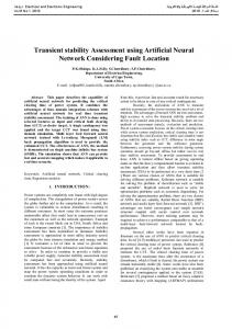
B. Operation in variable solar radiation conditions
Pout 1800
To visualize the behavior of our system in real conditions, we vary the irradiation as the increment step. These variations allow us to study the robustness of our system using ANN controller. We have tested the response of the two controllers, for a variation in solar radiation from 1000 W/m2 to 600 W/m2 in order to assess the relatively better performance of the ANN MPPT controller over other types classical P&O and ANN controllers.
1600 1400
Power(W)
1200 1000 800 600 400 200 0
Ipv 30 0
0.01
0.02
0.03
0.04
0.05 0.06 Time(sec)
0.07
0.08
0.09
0.1
25
Fig.23. The Boost converter output power with ANN controller Duty cycle
20 Current(A)
1.2
1
15
0.8
10
D
0.6
5 0.4
0
0.2
0
-0.2
0
0.01
0.02
0.03
0.04
0.05 0.06 Time(sec)
0.07
0.08
0.09
0.1
Fig. 27. The Boost converter output current with a step change of irradiance with ANN controller 0
0.01
0.02
0.03
0.04
0.05 0.06 Time(sec)
0.07
0.08
0.09
0.1
Vpv
Fig. 24. The duty cycle ‗D‘ variation
90 80
Vbat 46.5
70 60 Voltage(V)
46
Voltage(V)
45.5
50 40
45
30 44.5
20
44
10 0
43.5
43 0
0.01
0.02
0.03
0.04
0.05 0.06 Time(sec)
0.07
0.08
0.09
0.1
0
0.01
0.02
0.03
0.04
0.05 0.06 Time(sec)
0.07
0.08
0.09
0.1
Fig. 28. The Boost converter output voltage with a step change of solar irradiance with ANN controller
Fig. 25. The output battery voltage during the charging period
Ppv 2000
State of charge 100
1500 100
Power(W)
100
SOC
100
1000
500
100
0
100
100
99.9999
-500
0
0.01
0.02
0.03
0.04 0.05 0.06 Time(sec)
0.07
0.08
0.09
0.1
Fig. 26. The state of charge of the battery ‗SOC‘ using the ANN controller
Copyright © 2014 MECS
0
0.01
0.02
0.03
0.04
0.05 0.06 Time(sec)
0.07
0.08
0.09
0.1
Fig. 29. The Boost converter output Power with a step change of solar irradiance with ANN controller
I.J. Intelligent Systems and Applications, 2014, 12, 17-26
Tracking Power Photovoltaic System using Artificial Neural Network Control Strategy
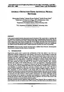
The simulation results illustrated in Figs. 27, 28 and 29 confirm that the ANN controller has good performance response such as rapidity and damping of the overshoot when the solar radiation decreases rapidly due to sudden shading for example during eclipses, considering that the PV temperature is kept constant at 25°C throughout the simulation time interval (0.1 sec.).
VII. CONCLUSION We have presented in this research work the detailed simulation of two methods of the maximum output power control in solar panel: the perturb and observe (P&O) and ANN controllers. Both of them were applied on a chain of energy conversion supplied using a DC/DC Boost converter. We compared the obtained simulation results, by subjecting the controlled system to the same environmental conditions. The simulation results have shown that the use of ANN controller can improve the efficiency of the overall system by minimizing the energy losses when the change of irradiation is frequent rather than the classical method P&O technique. We conclude that MPPT ANN controller, which is initially based on the experience of the operator during the training stage, has a very good transient performance. It improves the responses of the photovoltaic system: not only it reduces the time response to the track the maximum power point but it also eliminates the fluctuations around this point. This proves the effectiveness of the ANN control for photovoltaic systems under varying environmental conditions. The results obtained for this energy conversion system, show that by using the MPPT ANN controller, there is a compromise between rapidity in transient regime and stability in steady state. These controller results can be compared to other methods of control as using neural networks in optimizing the photovoltaic generator power. The idea of our future research work would be the use of a hybrid fuzzy-neural controller in order to better the PV system static and dynamic performances.
REFERENCES [1] C.L.B. Wu and R. Cheung. ―Advanced algorithm for MPPT control of photovoltaic systems‖. Canadian Solar Buildings Conference, Montreal, 2004. [2] E.I. Rivera. ―Maximum Power Point Tracking using the Optimal Duty Ratio for DC-DC Converters and Load Matching in Photovoltaic Applications‖. IEEE, pp. 987991, 2008. [3] J.A. Jiang, T.L. Huang, Y.T. Hsiao, and C.H. Chen Tamkangn. ―Maximum Power Tracking for Photovoltaic Power Systems‖. Journal of Science and Engineering, Vol. 8, No 2, pp. 147-153, 2005. [4] M.A. Elgendy, B. Zahawi, and D.J. Atkinson. ―Assessment of Perturb and Observe MPPT algorithm implementation techniques for PV pumping applications‖. IEEE transactions on sustainable energy, pp.21-33, Vol 3, No 1, 2012.
Copyright © 2014 MECS
25
[5] N. Femia, G. Petrone, Giovanni Spagnuolo, and Massimo Vitelli. ― Optimization of Perturb and Observe Maximum Power Point Tracking Method‖. Transactions on power electronics, pp.963-973, Vol 20, No 4, 2005. [6] T. Hiyama, S. Kouzuma, and T. Imakubo. ―Evaluation of neural network based real time maximum power tracking controller for PV system‖. IEEE Trans. Energy Conversion, vol. 10, pp. 543-548,1995b. [7] T.N. Tamer, A. Khatib, N. Mohamed, and K. Amin. ―An Efficient Maximum Power Point Tracking Controller for Photovoltaic Systems Using New Boost Converter Design and Improved Control Algorithm". WSEAS Transactions on power systems, April 2010, Issue 2, Vol. 5, pp. 53-60. [8] M. Veerachary, T. Senjyu, and K. Uezato. ―Neural Network Based Maximum Power Point Tracking of Coupled Inductor Interleaved Boost Converter Supplied PV System using Fuzzy Controller‖. IEEE Transactions on Industrial Electronics, Vol. 50, No. 4, pp. 749-758, August 2003. [9] G. Bin, D. Jason, J.S. Lai, Z. Zheng, and L. Chung. ―High boost ratio hybrid transformer DC-DC converter for photovoltaic module applications‖. IEEE Trans. Power Electron. 28, 2048–2058, 2013. [10] K.C. Tseng, C.C. Huang, and W.Y. Shih. ―A high stepup converter with a voltage multiplier module for a photovoltaic system‖. IEEE Trans. Power Electron. 2013, 28, 3047–3057. [11] H.H. Lee, L.M. Phuong, P.Q. Dzung, N.T. Dan Vu, and L.D. Khoa. ―The new maximum power point tracking algorithm using ANN-based solar PV systems‖. Proceedings of the IEEE Region 10 Conference (TENCON '10), pp. 2179–2184, Fukuoka, Japan, November 2010. [12] S. Daison Stallon, K. Vinoth Kumar, S. Suresh Kumar, and Justin Baby. ―Simulation of High Step-Up DC–DC Converter for Photovoltaic Module Application using MATLAB /SIMULINK‖. IJISA International Journal of Intelligent Systems and Applications. pp. 72-82, Vol 7, No 10, 2013. [13] R. De Keyser, J. Bonilla, and C. Ionescu. ―A Comparative Study of Several Control Techniques Applied to a Boost Converter‖. IEEE 10th Int Conf on Optimisation of Electrical and Electronic Equipment OPTIM, Brasov Romania, 71-78,ISBN 973-635-704-X, (Eds. Cernat, Nicolaide, Margineanu), 2006. [14] D. Vasarevicius, R. Martavicius, and Pikutis M. ―Application of Artificial Neural Networks for Maximum Power Point Tracking of Photovoltaic Panels‖. Elektronika ir Elektrotechnika, ISSN 1392-1215, Vol. 18, N°10, 2012. [15] M.A. Younis, T. Khatib, M. Najeeb, and M. Ariffin. ―An Improved Maximum Power Point Tracking Controller for PV Systems Using Artificial Neural Network‖. PRZEGLĄD ELEKTROTECHNICZNY (Electrical Review), pp.116–121, 2012. [16] B. Amrouche B, Belhamel M, Guessoum ―A. Artificial intelligence based P&O MPPT method for photovoltaic systems [R]‖. Revue des Energies Renouvelables (ICRESD-07), Tlemcen (2007), pp.11–16.
Authors’ Profiles Mohamed Tahar Makhloufi was born on February 06, 1961. He received the B.Sc. and M.Sc. degrees in Electronics from the University of Batna, Algeria, in 1986 and 2000, respectively. He is now teaching as a lecturer in Power Electronics and Control at the Department of
I.J. Intelligent Systems and Applications, 2014, 12, 17-26
26
Tracking Power Photovoltaic System using Artificial Neural Network Control Strategy
Electronics, Faculty of Engineering, and University of Batna. He has been a member of staff of Laboratory of Advanced Electronics (LEA) from 2002. He is a member of many research projects if Power electronics and control such as the applications of solar energy in autonomous vehicles and residential power supplies in remote areas. He has published three international papers in photovoltaic energy conversion and control using modern control techniques. His research interests include power resonant converters control using artificial intelligence strategies and their applications in various technical devices such as robots and artificial satellites.
Mohamed Salah Khireddine was born at Tolga (Algeria) in 1956. He obtained the Informatics Engineer Degree from the University of Algiers in 1980. He received his Doctorate (Ph.D) in Automation and computer science from the University of Aix-Marseille (France) in July 1990. In 2010 he received a postdoctoral degree in ―Habilitation of conducting research in Control Engineering‖ from the Batna University where he is currently Associate professor in Automation and Industrial Computing and research member in the Advanced Electronics Laboratory (LEA) and head of artificial intelligence team in Productics Research Laboratory (LRP). He is currently supervising many doctor‘s and master‘s thesis in different areas of power electronics and robotics. He has published ten papers in the real-time control of mobile robots, fault diagnosis and fault tolerant control of robot arms, and solar photovoltaic energy control. His research interests include Faults Diagnosis, Fault Tolerant Control, Artificial Intelligence, Control Systems and Robotics.
Abdelhalim Boutarfa was born in Lyon (France) in 1958. He has graduated from University of Constantine (Algeria) in Physics in 1982. He obtained the Electronic Engineer Degree from the Polytechnic School of Algiers in 1987, a Magister (Master) in 2002 and a Doctorate (PhD) in 2006 in ''Control Engineering'' at the University of Batna. In 2007 he received a postdoctoral degree in ―Habilitation of conducting research in Control Engineering‖ from the same University where he is currently full professor and research member in the Advanced Electronice Laboratory (LEA). He is also, since October 2010 the Project Manager of the National Center for Technology Transfer at the University of Setif (Algeria). His research interest includes applications of neural networks to pattern recognition, robotic vision, and industrial processes. He focuses his research on pattern recognition, learning, analysis and intelligent control of large scale complex systems.
Abdessemed Yassine was born on January, 28th 1959 at Batna, Algeria. He carried out under-graduated studies at the University of Constantine, Algeria from 1978 till 1980 and has obtained the degree of bachelor of engineering from the university of AlgiersENPA-Algiers, Algeria in June 1983. From 1985 till 1990 he carried out post- graduated and research studies in power electronics and real-time control of AC electrical drives. He was awarded the PhD degree from the department of electrical engineering of the University of Bristol, Great-Britain, in January 1991. Ha has the HDR degree from the University of Batna in 2007. He has been associate lecturer during five years at the electrical department, Faculty of Engineering of Bristol. He is now an associate professor in applied electronics, power electronics and control at the Department of Electronics of Batna. He has supervised many final year graduate projects and master by research thesis in electrical engineering and applied electronics, control and robotics. He is currently supervising many doctor‘s and master‘s thesis in different areas of power electronics and robotics. He has published five international papers in the real-time control of mobile robots, data fusion for the mobile robots localization, fault diagnosis and tolerant control of tele-operated robot arms, and solar photovoltaic energy control. His current main research work areas are power electronics, the neuro-fuzzy logic applied to the control of mobile robots and robot arms, and vision control of robot arms. He is a member of the artificial intelligence team in Productics Research Laboratory (LRP).
Copyright © 2014 MECS
I.J. Intelligent Systems and Applications, 2014, 12, 17-26