International Conference on Renewable Energies and Power Quality (ICREPQ’16) Madrid (Spain), 4th to 6th May, 2016 Renewable Energy and Power Quality Journal (RE&PQJ) ISSN 2172-038 X, No.14 May 2016
Traffic Lights Control Prototype Using Wireless Technologies J. Cunha1, C. Cardeira2, R. Melício2,3 1
Instituto Superior Técnico, Universidade de Lisboa Av. Rovisco Pais 1, 1049-001 Lisbon, Portugal 2
IDMEC/LAETA, Instituto Superior Técnico Av. Rovisco Pais 1, 1049-001 Lisbon (Portugal) 3
Departamento de Física, Escola de Ciências e Tecnologia, Universidade de Évora, Portugal e-mail:
[email protected];
[email protected];
[email protected]
Abstract.
This paper presents a traffic lights control prototype using wireless technologies, i.e., Arduino and XBee technologies, with at least 1 km range. The algorithm and the grid also allow flow of information between message boards and multiple wireless sensors networks in an interconnected system. The communication range between the points of interest can be changed according to the needs of each network, so that this prototype can be applied almost everywhere. The prototype in this paper allows great flexibility allowing the network to adapt to local failures or unforeseen cases. Even the control center can be moved to other place without large drawbacks, especially when compared to all the bunch of cables used in point to point connections.
Keywords Metropolitan area networks, communication system traffic control, electronic circuits, peer-to-peer computing, networked control systems.
1. Introduction Every major city has a large part of the population travelling by car or by public transportation, and traffic jams are a frequent problem [1]. Better public transportation is the sustainable long-term solution to road traffic jams. However, a nearer term solution is also required. The most obvious is to build new roads, but, in urban areas, this is generally not feasible, due to a lack of suitable land or insufficient funds [2]. Hence, the Traffic density is increasing at an alarming rate in developing countries which call for the need of intelligent traffic lights to replace the conventional manual and time based ones [3]. To solve this problem in Lisbon, Portugal since 1985 adopted a system called Gestion Electronique de Règulation en Temps Réel pour l’Urbanisme (GERTRUDE) [4].
The GERTRUDE system is a centralized management traffic control that from data supplied by sensors deployed in the pavement (1400+) and connected to a road control central allows the comparison between traffic flows and in real time react to each situation through traffic lights [5]. Currently GERTRUDE is a relatively old system. Even though the algorithm is still relevant and fully adequate, the hardware can be improved. Today, ways of thinking the cities are different. The quality of life in the cities is now the main goal of the cities strategic planning. New traffic systems have been developed to provide answers to these strategies [6]. The new traffic system areas, namely intelligent transportation system (ITS) combine the existing technology with artificial intelligence and wireless communication technologies that, in the limit, would truly think for themselves [7]. An ITS has to capture many environmental measurements in order improve the traffic quality of service. For example, a traffic lights network of a whole city can use weather and climate (air pollution) values to choose sequences time length in addition to the collected real-time data concerning vehicles (speed or queue length) [8]. The strategic works that have been carried out belong to an wider area of cities management, so called Smart Cities. Smart Cities go far beyond traffic management to include energy, water, and waste management among many other social aspects of the Cities. However the use of wireless technologies in cities remains relatively limited. Regarding traffic control, solutions exist for connecting traffic lights by GSM
networks. However they rely on an unique GSM operator, At the local level, some solutions exist for acquiring data from sensors (bellow the pavement) and wirelessly transmit their information to the local controller [9]. Wireless communication technologies have been developed but one in particular has received a lot of attention: ZigBee. This is a low power wireless networking standard designed for controlling and monitoring applications. The ZigBee standard was prepared by an industry consortium: the ZigBee alliance [10]. Using wireless technologies, is becomes easier to avoid traffic blockages in intersections and regulate the traffic lights action on secondary roads, managing the green light times and traffic panels information to facilitate the traffic flow and allowing the system to adapt to permanent fluctuations, as well as increasing the number and type of sensors that may be installed almost anywhere and provide important information to optimize traffic management. In local area solutions data acquired in a certain location is used there to know what road to open decided by any pre-programmed or pre-defined algorithm or local sensors. In wider area solutions for traffic control, the system processes the data acquired in the various locations with devices capable of doing so. They send information to all the local controllers not only to improve the traffic flow in that intersection but also in the neighbor intersections. This type of system also allows tracking of priority vehicles, like ambulances, to accommodate easier and quicker transportation of critical patients and public transportation priority roads. But there are some small issues with the system as well like problems with communication between controllers. The reaction capability of the system is limited to the central’s data analysis and there are no proactive capabilities aiming to prevent possible events that could be eventually foreseen. To have a functioning and applicable solution to a traffic control system, it has to be robust. The malfunction of any modules at any time is a possibility, so the choice of the type of grid must be done to avoid complications if this happens. Point-to-point and Star-type networks were ruled out because solutions based on networks in which the communication in the grid depend from the functioning of one module, have to be avoided. So a mesh-like grid is a type of network that’s not dependent from only one point at any time. Moreover, several paths area available for the same communication, which allows the prototype to carry its purpose successfully even if there are missing or malfunctioning modules. The purpose of this paper is to demonstrate that existing traffic control systems can be improved by the use of wireless technologies [11]. Wireless technologies present advantages and drawbacks but the trade-off between
them seems in favor of their use for traffic sensing and control.
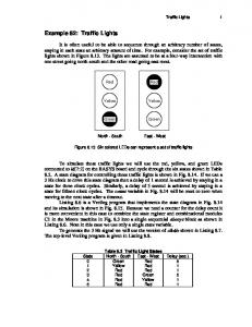
2. Prototype A. Configuration For the traffic lights control, the type of the grid used is vital for the success of the prototype which consists in several modules displayed in a grid that can communicate with each other allowing messages to flow from any module to another throughout the others. The configuration of the traffic lights prototype can be extrapolated to a real case. The prototype consists in one microcontroller (Arduino) per module that controls four traffic lights with three lights each, with the standard colors, red, yellow and green. The chosen protocol was ZigBee. ZigBee is a reliable, low power, low cost and efficient technology for the creation of information networks; a specification of high level communication protocol based on the LR-WPAN IEEE 802.15.4 standard extending that definition by developing the higher layers of the standard [12]. The ZigBee modules used in the field tests were built taking in consideration the most desirable features of the ZigBee protocol: the ability to create the data network mesh, the self-healing, security [12]. The ZigBee mesh with all the possible modules: the coordinator, the router and the end-points are shown in Figure 1.
Fig. 1. ZigBee mesh with all the possible modules.
The Application Programming Interface (API) is built on a frame based protocol consisting of five main parts: i) the start delimiter which is always “0x72”; ii) the length of frame data that has a two-byte value specifying the number of bytes that will be contained in the frame data field, not including the checksum; iii) the frame data portion that is composed by the API identifier and specific data; iv) the contents of the specific data that will change according to the API identifier; and finally, v) the checksum that is a byte containing the hash sum of the API frame bytes.
B. Protocol Developed The communication protocol is one of most sensible aspects about any communication system, not to mention the safety and privacy. At this phase of building the prototype it was important to focus not only on the communication and message delivery in the system but also receiving feedback from each module, to acknowledge the success of the transmission. An encrypted password is used to protect any relevant information. The protocol to communicate between every pair of modules in the grid was hence developed. At this phase no special protocol message size optimization was carried out, to keep the messages readiness. The validation of liveness and absence of deadlocks will be needed in a more complete version of the protocol developed. The hash symbol was used as a general separator, and SMSTART as a message starter. The final protocol format was decided to be:
If the coordinator needed to send a specific red light manual order to the third traffic light in the intersection number 23, the message sent, according this protocol, would be the following one: SMSTART#023#3#MANUAL#RED#PASSWORD#CRC
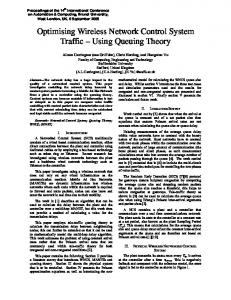
If the coordinator needed the intersection to start the selfmanagement automatic mode the message would be: SMSTART#023#ALL#AUTO#ON#PASSWORD#CRC The coordinator sends the information to different modules through a broadcast message. Each module interprets the message and checks if the message is assigned to it or not. This was the implementation for the prototype a real wider case would require a unicast to the specific device and avoid the intensive use of multicasts. The flowchart of the prototype system is shown in Figure 2.
STARTER#INTERSECTION#TRAFFICLIGHT# … … OPERATION MODE#ORDER#PASSWORD#CRC
Fig. 2. Flowchart of the System.
3. Experimental Setup To develop this work two Arduinos and three ZigBee modules were used. With these, a network between two routers (in AT mode) and a coordinator (in API mode) was formed. With the coordinator constantly connected to a computer receiving and sending information. Using the X-CTU, the property program of the company that develops ZigBee, it was possible to access the list of packets received on the coordinator. A testing program was loaded into each of the routers for them to send information to the coordinator that could be worked on.
The test program consisted in increments of a number every 5 s, information which was sent from ZigBee by each of the routers on broadcast to the coordinator. These tests were made to verify the communication limits between the various modules. The tests were carried out in the Control Automation and Robotics Laboratory of the Center of Intelligent Systems of IDMEC/Instituto Superior Técnico. With the list of packets received created, a MATLAB script was developed to treat and analyze this data. Both
the packets received and those not received were registered in order to be later analyzed for this study.
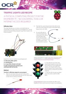
4) Case 4: One module on the coordinators limit range and the other one outside shown on Figure 6.
For electronics and connections some LED strips of various colors (Red, Yellow and Green) were prepared. Using transistors to help in the commuting of the traffic lights a circuit board was created to connect the traffic lights to Arduino in order for them to be controlled. The testing program was replaced by one that would interpret the developed protocol presented earlier. All the tests to assure the information sent by the coordinator and vice-versa were interpreted correctly were made. Fig. 6. Representation of Case 4.
4. Experimental Results As a simulation of possible range or connection related issues four tests were done in four different situations. Measurements were taken in the same place and same distances. The following cases were considered to check the packet reception ratio (PRR):
1) Case
1: All the modules within communications range shown on Figure 3.
the
To evaluate the ratio between the sent and received packets, the routers were programmed to send an ASCII character with a number from 1 incrementing for each packet sent, with a 5 s delay. Based on the serial sent by each router, through MATLAB it was possible to evaluate offline the packet reception ratio given by PRR
pr pr ps pr pnr
(1)
where pr is the packets received, ps the packets sent, pnr the packets not received. Table I shows a better overview of the results obtained.
Fig. 3. Representation of Case 1.
2) Case 2: One module disconnected. The other is located in the limit range shown on Figure 4.
Case 1 Results: This case consists of having the two routers within the coordinators range. As expected the PRR was around 97% on Router 1 and 100% on Router 2 (in the experiment made). The small percentage of packets lost may be caused by the delays on the initialization process. As expected there were no major delays in the packet reception. The expected 5 s delay was obtained with very low variance. The time intervals between the data received for this case are shown in Figure 7.
Fig. 4. Representation of Case 2.
3) Case 3: All modules connected but one in the limit range shown on Figure 5.
Fig. 7. Time intervals between the data received.
Fig. 5. Representation of Case 3.
Case 2 Results: This case consists of having only one router on his range limit.
Table I. Overview of the results obtained Data Analysis Cases Source
Mean time per packet [s]
Maximum time per packet [s]
Minimum time per packet [s]
Packet reception ratio (PRR)
Router 1
5.0068
5.0340
4.9730
97.33
Router 2
5.0047
5.0380
4.9460
100
Router 1 (OFF)
NA
NA
NA
NA
Router 2
6.1841
26.4100
0.7650
79.80
Router 1
5.0083
5.1250
4.8730
96.34
Router 2
5.3491
31.1570
4.6940
92.68
Router 1
6.6024
20.1980
2.0120
74.75
Router 2
10.8373
127.3110
1.7620
44.33
Case 1
Case 2
Case 3
Case 4
The purpose of this case was to evaluate how the positioning of the router would affect the PRR. The results weren’t so good as in Case 1. However a nearly 80% PRR doesn’t compromise the system. Since, in the real case, the coordinators would be set in API mode, the system can always resend the message. In this case the packet reception time mean has raised about 1 second. The time intervals between the data received are shown in Figure 8.
Fig. 9. Time intervals between the data received.
Fig. 8. Time intervals between the data.
Case 3 Results: Having a router between the limit range router and the coordinator, should improve the PRR of the one in his limit range from the base. This objective was successfully achieved. The time intervals between the data received are shown in Figure 9. However due to some issues during the start of the test the first packet took a lot of time to arrive to the coordinator, so we have ignored the initial points shown in Figure 10. This way we can see better the time oscillations between packet arrivals.
Fig. 10. Time intervals between the data received without the initial points.
Case 4 Results: This case study corresponds to the communication being done through all the devices to
reach the coordinator. One router is placed on the range limit and the other router is placed out of range of the coordinator. The influence of the communication transmission of one router through the other one at his limit range is shown in Figure 11. A lot of packets have been lost and take a lot to reach coordinator. In Table I this is the worst scenario with the lowest percentage of packet reception ratio. These four case studies have measured the performance of the experimental setup to implement a prototype of a traffic control wireless intelligent network.
Tests were performed to limit and extreme distance situations. Results were positive guaranteeing the communication between modules keeping a decent packets received ratio.
Acknowledgments This work was supported by the Portuguese Foundation for Science & Technology, through IDMEC, under LAETA, project UID/EMS/50022/2013
References [1]
Fig. 11. Time intervals between the data received.
5. Conclusion Today, ways of thinking the cities are different. The quality of life in the cities is now the main goal of the cities mayors and authorities. This paper contributes to find an alternative solution to outdated traffic systems making them communicate using grid based wireless devices. The Zigbee’s network properties showed good performance for the traffic system control prototype. Usually it is necessary to add, replace or remove modules from the grid for various reasons. Zigbee’s use a selfforming network so there’s no need for manual reconfiguration. The possible malfunction issues on any nodes are solved due to the self-healing properties of the Zigbee network that allows the network to adjust routes from and to modules if the network changes. Regarding the communication efficiency, ZigBee provides satisfactory results, especially when in a grid.
K.M. Yousef, J.N. Al-Karaki, and A.M. Shatnawi, “Intelligent trafic flow control system using wireless sensors networks”, Journal of Information Science and Engineering, vol. 26, pp. 753–768, 2010. [2] A.N. Knaian, “A wireless sensor network for smart roadbeds and intelligent transportation systems”, MsC Thesis, Massachusetts Institute of Technology, USA, 2000. [3] R. Hussian, S. Sharma, and V. Sharma, “WSN applications : automated intelligent traffic control system using sensors.”, International Journal of Soft Computer and Engineering, vol. 3, pp. 77–81, 2013. [4] M.A. Vieira, “Melhoria da velocidade dos transportes públicos de superfície em Lisboa por regulação da admissão de trânsito,” MsC Thesis, Instituto Superior Técnico, Portugal, 2004. [5] http://blog.ritabatatafrita.com/2009/04/sistema-gertrudeafinal-nao-estou-louca.html, 2015. [6] E. Franceries, and K. Liver, “Centralized traffic management system as response to the effective realization of urban traffic fluency”, Archives of Transportation Telematics, vol. 4:4, pp. 4–10, 2011. [7] Smart traffic light, https://en.wikipedia.org/wiki/Smart_traffic_light, 2015. [8] M.A. Kafi, Y. Challal, D. Djenouri, M. Doudou, A. Bouabdallah, and N. Badache, “A study of wireless sensor networks for urban traffic monitoring: applications and architectures”, Procedia Computer Science, vol. 19, pp. 617–626, 2013. [9] Sitraffic wimag: wireless magnetic detector, innovation in traffic detection, www.siemens.com/mobility, 2015. [10] N.C. Batista, R. Melício, J.C.O. Matias, and J.P.S. Catalão, “Photovoltaic and wind energy systems monitoring and building/home energy management using ZigBee devices within a smart grid”, Energy vol. 49, pp. 306–315, 2013. [11] C. Cardeira, A. W. Colombo, R. Schoop, “Wireless solutions for automation requirements”, in ATP International – Automation Technology in Practice, IFACaffiliated journal, vol. 2, September 2006, pp 51-58. [12] N.C. Batista, R. Melício, and V.M.F. Mendes, “Layered smart grid architecture approach and field tests by ZigBee technology”, Energy Conversion and Management, vol. 88, pp. 49–59, 2014.