Policy-based Wide Area Network Management System 1
Kazuya Odagiri, 2Shogo Shimizu, 3Naohiro Ishii 1 Yamaguchi University ,Yamaguchi, Japan; 2Gakushuin Women's College, Tokyo, Japan 3 Aichi Institute of Technology, Aichi, Japan 1
[email protected]; 1
[email protected];
[email protected] 3
[email protected];
ABSTRACT In the current Internet-based systems, there are many problems using anonymity of the network communication such as personal information leak and crimes using the Internet systems. This is because the TCP/IP protocol used in Internet systems does not have the user identification information on the communication data, and it is difficult to supervise the user performing the above acts immediately. As a solution for solving the above problem, there is the approach of Policy-based Network Management (PBNM). This is the scheme for managing a whole Local Area Network (LAN) through communication control of every user. In this PBNM, two types of schemes exist. The first is the scheme for managing the whole LAN by locating the communication control mechanisms on the course between network servers and clients. The second is the scheme of managing the whole LAN by locating the communication control mechanisms on clients. As the second scheme, we have been studied theoretically about the Destination Addressing Control System (DACS) Scheme. By applying this DACS Scheme to Internet system management, we realize the policy-based Internet system management. In this paper, we show the DACS system theoretically. Keywords: Policy-based network management, DACS Scheme, NAPT
1.
INTRODUCTION
In the current Internet systems, there are many problems using anonymity of the network communication, such as personal information leak and crimes using the Internet systems. The news of the information leak in the big company is sometimes reported through the mass media. Because TCP/IP protocol used in Internet systems does not have the user identification information on the communication data, it is difficult to supervise the user performing the above acts immediately. Many solutions and technologies for managing Internet systems based on TCP/IP protocol have been emerged, namely, Domain Name System (DNS) [3], Routing protocols, firewall (F/W) [7], and Network Address Port Translation (NAPT) [8] / Network DOI: 10.14738/tnc.23.192 Publication Date: 12th June 2014 URL: http://dx.doi.org/10.14738/tnc. 23.192
Kazuya Odagiri, Shogo Shimizu, Naohiro Ishii; Policy-based Wide Area Network Management System, Transactions on Networks and Communications. Volume 2 No 3 (2014) PP 01-17
Address Translation (NAT) [9]. However, they are for managing the specific part of the Internet systems, and have no purpose of solving our target problems. PBNM might be a solution for solving these problems. However, it is a scheme for managing a whole LAN through communication control of every user, and cannot be applied to the Internet systems. It is often used in a scene of campus network management. In a campus network, network management is quite complicated. Because a network administrative department manages only a small portion of the wide needs of the campus network, there are some user support problems. For example, when mail boxes on one server are divided and relocated to some different server machines, it is necessary for some users to update a client machine’s setups. Most of computer network users in a campus are students. Because they do not check frequently their e-mail, it is hard work to make them aware of the settings update. This administrative operation is executed by means of web pages and/or posters. For the system administrator, it is difficult to support every student in terms of time and workload. Because the PBNM manages a whole LAN, it is easy to solve this kind of problem. In addition, for the problem such as personal information leak, the PBNM can manage a whole LAN by making anonymous communication non-anonymous. As the result, it becomes possible to identify the user who steals personal information and commits a crime swiftly and easily. Therefore, by applying the PBNM, we study about the policy-based Internet system management. In the existing PBNM, there are two types of schemes. The first is the scheme of managing the whole LAN by locating the communication control mechanisms on the course between network servers and clients. The second is the scheme of managing the whole LAN by locating the communication control mechanisms on clients. It is difficult to practically apply the first scheme to Internet system management, because the communication control mechanism needs to be located on the course between network servers and clients necessarily. Because the second scheme locates the communication control mechanisms as the software on each client, it becomes possible to apply the second scheme to Internet system management by devising the installing mechanism so that users can install the software to the client easily. As the second scheme, we have been studied, theoretically, about the Destination Addressing Control System (DACS) Scheme. As the works on the DACS Scheme, we showed the basic principle of the DACS Scheme [28], and security function [29]. After that, we implemented a DACS system to realize a concept of the DACS Scheme [30]. By applying this DACS Scheme to Internet systems, we realize the policy-based Internet system management. In this paper, we show the encrypting mechanism, which is suitable for the wDACS system. In Section II, motivation and related research are described. Existing DACS Scheme are described in Section III. Then, in Section IV, the wDACS system is suggested and experimental results for confirming the possibility of the wDACS system.
URL: http://dx.doi.org/10.14738/tnc.23.192
2
TRANSACTIONS
ON
NETWORKS
AND
COMMUNICATIONS, VOLUME 2, NO3 (JUNE 2014)
2. MOTIVATION AND RELATED RESERACH
In the current Internet systems, problems using anonymity of the network communication, such as personal information leak and crimes using the Internet systems occur. Because the TCP/IP protocol used in Internet systems does not have the user identification information on the communication data, it is difficult to supervise the user performing the above acts immediately. Many solutions and technologies for Internet systems management using TCP/IP [1][2] have been proposed and are in use: 1) DNS [3] 2) Routing protocols: a. Interior Gateway Protocols (IGP), such as Routing Information Protocol (RIP) [4] and Open Shortest Path First (OSPF) [5] b. Exterior Gateway Protocols (EGP), such as Border Gateway Protocol (BGP) [6] 3) F/W [7] 4) NAT [8] / NAPT [9] 5) Load balancing [10][11] 6) Virtual Private Network (VPN) [12][13] 7) Public Key Infrastructure(PKI) [14] 8) Server virtualization [15] However, they are for managing the specific aspect of the Internet systems, but have no purpose of solving our target problems. In the following, we are focusing on policy-based thinking, to study the policy-based Internet system management.
Figure 1. Principle in the first scheme.
Copyright © SOCIETY
FOR
SCIENCE
AND
EDUCATION UNITED KINGDOM
3
Kazuya Odagiri, Shogo Shimizu, Naohiro Ishii; Policy-based Wide Area Network Management System, Transactions on Networks and Communications. Volume 2 No 3 (2014) PP 01-17
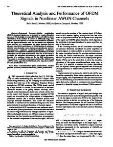
In PBNM, there are two types of schemes. The first scheme is described in Figure 1. This scheme is standardized in various organizations. In IETF, a framework of PBNM [16] was established. Standards about each element constituting this framework are as follows. As a model of control information stored in the server called Policy Repository, Policy Core Information model (PCIM) [17] was established. After it, PCMIe [18] was established by extending the PCIM. To describe them in the form of Lightweight Directory Access Protocol (LDAP), Policy Core LDAP Schema (PCLS) [19] was established. As a protocol to distribute the control information stored in Policy Repository or decision result from the Policy Decision Point (PDP) to the Policy Enforcement Point (PEP), Common Open Policy Service (COPS) [20] was established. PDP is the point which performs the judgment about the communication control, and PEP is the point which performs the communication control based on the judgment. Based on the difference in distribution method, COPS usage for RSVP (COPS-RSVP) [21] and COPS usage for Provisioning (COPS-PR) [22] were established. RSVP is an abbreviation for Resource Reservation Protocol. The COPS-RSVP is the method as follows. After the PEP detected the communication from a user or a client application, the PDP makes a judgmental decision for it. The decision is sent and applied to the PEP, and the PEP adds the control to it. The COPS-PR is the method of distributing the control information or decision result to the PEP before accepting the communication. Next, in the Distributed Management Task Force (DMTF), a framework of PBNM called Directory-enabled Network (DEN) was established. Like the IETF framework, control information is stored in the server called Policy Server which is built by using the directory service, such as LDAP [23], and is distributed to network servers and networking equipment such as switch and router. As the result, the whole LAN is managed. The model of control information used in DEN is called Common Information Model (CIM); the schema of CIM (CIM Schema Version 2.30.0) [25] was published. CIM was extended to support DEN [24], and was incorporated in the framework of DEN. In addition, Resource and Admission Control Subsystem (RACS) [26] was established in Telecoms and Internet converged Services and protocols for Advanced Network (TISPAN) of European Telecommunications Standards Institute (ETSI), and Resource and Admission Control Functions (RACF) [27] was established in International Telecommunication Union Telecommunication Standardization Sector (ITU-T). However, all the frameworks explained above are based on the principle shown in Figure 1. As problems of these frameworks, two points are presented as follows. Essential principle is described in Figure 2. To be concrete, in the PDP, judgment such as permission and nonpermission for communication pass is performed based on policy information. The judgment is notified and transmitted to the point called the PEP. Based on that judgment, the control is added for the communication that is going to pass by.
URL: http://dx.doi.org/10.14738/tnc.23.192
4
TRANSACTIONS
ON
NETWORKS
AND
COMMUNICATIONS, VOLUME 2, NO3 (JUNE 2014)
Figure 2. Essential Principle.
The principle of the second scheme is described in Figure 3 [28][29][30][31]. By locating the communication control mechanisms on the clients, the whole LAN is managed. Because this scheme controls the network communications on each client, the processing load is low. However, because the communication control mechanisms need to be located on each client, the workload becomes heavy. We aim at realizing the PBNM management of an Internet system by applying these two schemes. However, it was difficult to apply the first scheme to Internet system management practically. In the first scheme, the communication control mechanism needs to be located on the course between network servers and clients, necessarily. As the result, the mechanism is operated from outside. It is more likely to violate the network and security policy of each organization.
Figure 3. Principle in second scheme.
On the other hand, the second scheme locates the communication controls mechanisms on each client. The software for communication control is installed on each client. Therefore, by devising the installing mechanism letting users install software to the client easily, it becomes possible to apply the second scheme to Internet system management. Copyright © SOCIETY
FOR
SCIENCE
AND
EDUCATION UNITED KINGDOM
5
Kazuya Odagiri, Shogo Shimizu, Naohiro Ishii; Policy-based Wide Area Network Management System, Transactions on Networks and Communications. Volume 2 No 3 (2014) PP 01-17
3. EXISTING DACS SCHEME
3.1 Basic Principle of the DACS Scheme Figure 4 shows the basic principle of the network services by the DACS Scheme. At the processing of the (a) or (b), as shown in the following, the DACS rules (rules defined by the user unit) are distributed from the DACS Server to the DACS Client. a) Processing of a user logging in the client. b) Processing of a delivery indication from the system administrator. According to the distributed DACS rules, the DACS Client performs (1) or (2) operation. Then, communication control of the client is performed for every user used for login. 1) Destination information on IP Packet, which is sent from application program, is changed. 2) IP Packet from the client, which is sent from the application program to the outside of the client, is blocked. An example of the case (1) is shown in Figure 4. In Figure 4, the system administrator can distribute a communication of the user used for login to the specified server among servers A, B or C. Moreover, the case (2) is described. For example, when the system administrator wants to forbid an user to use Mail User Agent (MUA), it is performed by blocking IP Packet with the specific destination information.
Figure 4. Basic Principle of the DACS Scheme.
In order to realize the DACS Scheme, the operation is done by a DACS Protocol, as shown in Figure 5. As shown by (1) in Figure 5, the distribution of the DACS rules is performed on communication between the DACS Server and the DACS Client, which is arranged at the application layer. The application of the DACS rules to the DACS Control is shown by (2) in Figure 5.
URL: http://dx.doi.org/10.14738/tnc.23.192
6
TRANSACTIONS
ON
NETWORKS
AND
COMMUNICATIONS, VOLUME 2, NO3 (JUNE 2014)
Figure 5. Operation of the DACS Protocol.
The steady communication control, such as a modification of the destination information or the communication blocking is performed at the network layer, as shown by (3) in Figure 5. 3.2 Communication Control on Client The communication control of every user was given. However, it may be better to perform communication control every client instead of every user. For example, it is the case where many and unspecified users use a computer room, which is controlled. In this section, the method of communication control every client is described, and the coexistence method with the communication control of every user is considered. When a user logs in to a client, the IP address of the client is transmitted to the DACS Server from the DACS Client. Then, if the DACS rules corresponding to IP address, is registered into the DACS Server side, it is transmitted to the DACS Client. Then, communication control for every client can be realized by applying to the DACS Control. In this case, it is a premise that a client uses a fixed IP address. However, when using DHCP service, it is possible to carry out the same control to all the clients linked to the whole network or its sub network. i.e.
Figure 6. Creating the DACS rules on the DACS Server.
Copyright © SOCIETY
FOR
SCIENCE
AND
EDUCATION UNITED KINGDOM
7
Kazuya Odagiri, Shogo Shimizu, Naohiro Ishii; Policy-based Wide Area Network Management System, Transactions on Networks and Communications. Volume 2 No 3 (2014) PP 01-17
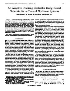
When using the communication control of every user and every client, communication control may conflict. In that case, a priority needs to be given. The judgment is performed in the DACS Server side as shown in Figure 6. Although not necessarily stipulated, the network policy or security policy exists in the organization, such as a university (1). The priority is decided according to the policy (2). In (a), priority is given for the user's rule to control communication by the user unit. In (b), priority is given for the client's rule to control communication by the client unit. In (c), the user's rule is the same as the client's rule. As the result of comparing the conflict rules, one rule is determined, respectively. Those rules and other rules not overlapping are gathered, and the DACS rules are created (3). The DACS rules are transmitted to the DACS Client. In the DACS Client side, the DACS rules are applied to the DACS Control. The difference between the user's rule and the client's rule is not distinguished. 3.3 Security Mechanism of the DACS Scheme In this section, the security function of the DACS Scheme is described. The communication is tunneled and encrypted by use of Secure Shell (SSH) [31]. By using the function of port forwarding of SSH, it is realized to tunnel and encrypt the communication between the network server and the DACS Client, which the DACS Client is installed in. Normally, to communicate from a client application to a network server by using the function of port forwarding of SSH, the local host (127.0.0.1) needs to be indicated on that client application as a communicating server. The transparent use of a client as the virtue of the DACS Scheme is lost. The transparent use of a client means that a client can be used continuously without changing setups when the network system is updated. The function that does not fail the transparent use of a client is needed. The mechanism of that function is shown in Figure 7.
Figure 7. Extend Security Function.
The changed point on network server side is shown as follows, in comparison with the existing DACS Scheme. SSH Server is located and activated, and communication, except, SSH is blocked.
URL: http://dx.doi.org/10.14738/tnc.23.192
8
TRANSACTIONS
ON
NETWORKS
AND
COMMUNICATIONS, VOLUME 2, NO3 (JUNE 2014)
In Figure 7, the DACS rules are sent from the DACS Server to the DACS Client (a). On the DACS Client that accepts the DACS rules, the DACS rules are applied to the DACS Control in the DACS Client (b). These processes are same as the existing DACS Scheme. After functional extension, as shown in (c) of Figure 7, the DACS rules are applied to the DACS SControl. Communication control is performed in the DACS SControl with the function of SSH. By adding the extended function, selecting the tunneled and encrypted or not tunneled and encrypted communication is done for each network service. When communication is not tunneled and encrypted, communication control is performed by the DACS Control, as shown in (d) of Figure 7. When communication is tunneled and encrypted, destination of the communication is changed by the DACS Control to localhost, as shown in Figure 7. In Figure 7, the communication to localhost is shown with the arrows from (e) to the direction of (f). After that, by the DACS SControl which is used for the VPN communication, the communicating server is changed to the network server and tunneled and encrypted communication is sent as, shown in (g) of Figure 7, which are realized by the function of port forwarding of SSH. In the DACS rules applied to the DACS Control, localhost is indicated as the destination of communication. As the functional extension explained in the above, the function of tunneling and encrypting communication is realized in the state of being suitable for the DACS Scheme, that is, with the transparent use of a client. Distinguishing the control in the case of tunneling and encrypting or not tunneling and encrypting by a user unit is realized by changing the content of the DACS rules applied to the DACS Control and the DACS SControl. By tunneling and encrypting the communication for one network service from all users, and blocking the not tunneled and decrypted communication for that network service, the function of preventing the communication for one network service from the client, which DACS Client is not installed in, is realized. Moreover, the communication to the network server from the client on which DACS Client is not installed in is permitted; each user can select whether the communication is tunneled and encrypted or not. 3.4 Technical Points in Implementation of DACS System (a) Communications between the DACS Server and the DACS Client The Communications between the DACS Server and the DACS Client such as sending and accepting the DACS rules were realized by the communications through a socket in TCP/IP. (b) Communication control on the client computer In this study, the DACS Client working on windows XP was implemented. The functions of the destination NAT and packet filtering required as a part of the DACS Control were implemented by using Winsock2 SPI of Microsoft. As it is described in Figure 8, Winsock2 SPI is a new layer which is created between the existing Winsock API and the layer under it. To be concrete, though connect() is performed when the client application accesses the server, the processes of destination NAT for the communication from the client application are built in WSP connect() which is called in connect(). In addition, though accept() is performed on
Copyright © SOCIETY
FOR
SCIENCE
AND
EDUCATION UNITED KINGDOM
9
Kazuya Odagiri, Shogo Shimizu, Naohiro Ishii; Policy-based Wide Area Network Management System, Transactions on Networks and Communications. Volume 2 No 3 (2014) PP 01-17
the client when the communication to the client is accepted, the function of packet filtering is implemented in WSPaccept() which is called in accept().
Figure 8. Winsock2 SPI.
(c) VPN communication The client software for the VPN communication, that is, the DACS SControl was realized by using the port forward function of the Putty. When the communication from the client is supported by the VPN communication, first, the destination of this communication is changed to the localhost. After that, the putty accepts the communication, and sends the VPN communication by using the port forward function.
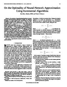
4. WDACS SYSTEM In this section, the content of wDACS system is explained. 4.1 System Configuration of wDACS system The system configuration of the wDACS system is described in Figure 9.
Figure 9. Basic System Configuration of wDACS system
URL: http://dx.doi.org/10.14738/tnc.23.192
10
TRANSACTIONS
ON
NETWORKS
AND
COMMUNICATIONS, VOLUME 2, NO3 (JUNE 2014)
First, as preconditions, because private IP addresses are assigned to all servers and clients existing in from LAN1 to LAN n, mechanisms of NAT/NAPT are necessary for the communication from each LAN to the outside. In this case, NAT/NAPT is located on the entrance of the LAN such as (1), and the private IP address is converted to the global IP address towards the direction of the arrow. Next, because the private IP addresses are set on the servers and clients in the LAN, other communications except those converted by Destination NAT cannot enter into the LAN. But, responses for the communications sent form the inside of the LAN can enter into the inside of the LAN because of the reverse conversion process by the NAT/NAPT. In addition, communications from the outside of the LAN1 to the inside are performed through the conversion of the destination IP address by Destination NAT. To be concrete, the global IP address at the same of the outside interface of the router is changed to the private IP address of each server. From here, system configuration of each LAN is described. First, the DACS Server and the authentication server are located on the DMZ on the LAN1 such as (4). On the entrance of the LAN1, NAT/NAPT and destination NAT exists such as (1) and (2). Because only the DACS Server and network servers are set as the target destination, the authentication server cannot be accessed from the outside of the LAN1. In the LANs from LAN 2 to LAN n, clients managed by the wDACS system exist, and NAT/NAPT is located on the entrance of each LAN such as (1). Then, F/W, such as (3) or (5), exists behind or with NAT/NAPT in all LANs. 4.2 Key ExchangeMechanism for wDACS system
Figure 10. Mechanism of Key Exchange.
Copyright © SOCIETY
FOR
SCIENCE
AND
EDUCATION UNITED KINGDOM
11
Kazuya Odagiri, Shogo Shimizu, Naohiro Ishii; Policy-based Wide Area Network Management System, Transactions on Networks and Communications. Volume 2 No 3 (2014) PP 01-17
This is a periodical key exchange mechanism which is necessary for encrypted communications between the network servers and the client computers. This mechanism is incorporated at the last part of the initialization process of the DACS Client. The preconditions are as follows. a) b) c)
The communications between the DACS Client and the Web Server are encrypted by the https. The communications between the Server Machine moving the Web Server and network servers are encrypted by SSH. This mechanism is located on the Server Machine which is separated physically with DACS Sever for the management of a large-scale network with many clients.
Next, the processing of this mechanism is described. First, the key request is performed from the DACS Client (1). The program on the Web Server receives the request, and creates two kinds of keys which are a public key and a private key (2). Then, the program sends the private key to the client (3). The public key stored in the home directory on the Server Machine is copied and stored on the network server by mirroring through SSH. To be concrete, network commands such as rsync and rdiff-backup are used. The mirroring process is performed just before the transmission of the private key. 4.3 Encrypted Communication Mechanism for the wDACS system In this section, two functions to realize the encrypted communication are described. (1) Function of encrypted communications in user authentication processes In this section, the function of the encrypted communications in user authentication processes, which is suitable for the wDACS system, is described. The content of the function is shown in Figure 11.
Figure 11. Function of user authentication processes.
First, authentication request is performed form the DACS Client to the program on the Web Server (1). The Program performs inquiry to the LDAP Server which stores user accounts (user
URL: http://dx.doi.org/10.14738/tnc.23.192
12
TRANSACTIONS
ON
NETWORKS
AND
COMMUNICATIONS, VOLUME 2, NO3 (JUNE 2014)
name, pass word) (2). As the result, if authentication is not permitted, the results are notified to the DACS Client (3-a). The DACS Client stops performing subsequent processing. If authentication is permitted, the results are notified to the DACS Server (3-b). The DACS Server performs the processing described in next section. (2) Function of encrypted communications
Figure 12. Function of transmission and reception processes for control information.
In this section, the function of the encrypted communications in the DACS rule’s transmission and reception processes, which is suitable for the wDACS system, is described. First, as a part of process (1) in Figure 11, the IP address of the client where the DACS Client is installed is notified with user name and password to the program on the Web Server. This process is described as process (x) in Figure 12, which is shown by a dotted arrow. Next, based on them, the program performs a request of the DACS rules to the DACS Server (1). The DACS rules are extracted from the database of the DACS Server, and sent to the program on the Web Server (2). The program receives them, and sends to the DACS Client. Specific to these two functions is the use of HTTPS. Because this wDACS system needs to be extended for Internet management, we chose HTTPS used widely in the world of the Internet. 4.4 Experiments for confirming the possibility of the wDACS system To confirm the possibility of the wDACS Scheme, we performed a functional experiment. By this experiment, we confirmed that the existing DACS Scheme could be operated in cloud environment. 4.4.1 Constitution of the experiment system In Figure 12, the experiment system used in this research was described. Two virtual servers which placed VMWare ESXi 5.1 were prepared. Each virtual server was constructed as follows.
Copyright © SOCIETY
FOR
SCIENCE
AND
EDUCATION UNITED KINGDOM
13
Kazuya Odagiri, Shogo Shimizu, Naohiro Ishii; Policy-based Wide Area Network Management System, Transactions on Networks and Communications. Volume 2 No 3 (2014) PP 01-17
Figure.13 Experiment system
(1) Virtual Server 1 (CPU:2.8GHz 4Core×1 Memory:16GB) Virtualization software: VMWareESXi5.1 Virtual machine A: Operating System (CentOS6.5) Software for DACS Server Virtual machine B: Operating System (CentOS6.5) Authentication server (OpenLDAP2.4) Virtual machine C: Operating System (CentOS6.5) Windows domain server (Samba3.6) Virtual router for a gateway (Vyatta6.6:64bit)
(2) Virtual Server 2 (CPU:2.6GHz 4Core×1 Memory:16GB) Virtualization software: VMWareESXi5.1 Each virtual machine (5 virtual machine): Operating System (Windows XP Pro) Software for DACS Client Virtual router for a gateway (Vyatta6.6:64bit)
URL: http://dx.doi.org/10.14738/tnc.23.192
14
TRANSACTIONS
ON
NETWORKS
AND
COMMUNICATIONS, VOLUME 2, NO3 (JUNE 2014)
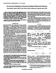
Because we assumed that a service based on this scheme would be offered in the cloud environment, we prepared the experimental environment which each virtual router on each virtual server is connected by IPsec VPN each other. The DACS Server was located on the virtual machine in the virtual server 1. The DACS Client was located on each virtual client in the virtual server 2, and the DACS Client was located on the CentOS in each virtual machine. The policy information was sent and received through the VPN connected by two virtual routers on each virtual server. 4.4.2 Content of the functional experiment By using the experiment system in Figure 13, we performed the function experiments about two functions as follows. (a) User authentication function In this experimental system, the Windows OS (XP Pro) is used as an operating system on each virtual machine in the virtual server 2. In addition, because we intend to release the software developed to realize this scheme, we adopt the user authentication mechanism by free software. To be concrete, the user authentication is realized by the cooperation of two kinds of servers as follows. To be concrete, user authentication processes are performed between the clients on the virtual server 2 and the DACS Server on the virtual server1. About this point, we could confirm the movement normally. (Server1) OpenLDAP server for managing user accounts (Server2) Samba server for building a windows domain (b) Delivery function of policy information In this scheme, after the process (a), the policy information is sent and received through the VPN connected by two virtual routers on each virtual server. About this process, I performed two cases of movement experiments as follows. (Case1) One virtual machine was operated on the virtual server 2. (Case2) Some virtual machines (Five virtual machines) were operated on the virtual server 2. 4.4.3 Result of functional experiment In the above both cases, the DACS system was operated with no problem. Then, the communication log was shown in Figure 14.
Figure. 13 Communication log on the DACS Client
As the result, we could confirm that the DACS Scheme to premise a physical client conventionally was operated in cloud environment. However, when we prepared the experimental system, it was burden to make many virtual machines in the virtual server 2. At Copyright © SOCIETY
FOR
SCIENCE
AND
EDUCATION UNITED KINGDOM
15
Kazuya Odagiri, Shogo Shimizu, Naohiro Ishii; Policy-based Wide Area Network Management System, Transactions on Networks and Communications. Volume 2 No 3 (2014) PP 01-17
this point, the mechanism for managing many virtual machines is necessary in the form that adapted to the DACS Scheme. After this research, we will study as another research.
5. CONCLUSION In this paper, we showed the policy-based wide area network management system called wDACS system. This system is realized by the extension of the policy-based network management system called the DACS system, which is the management scheme of the LAN one organization hold. As a future study, the wDACS system will be implemented by incorporating three functions suggested in this paper, and evaluations will be performed. REFERENCES [1]. V. Cerf and E. Kahn, "A Protocol for Packet Network Interconnection," IEEE Trans. on Commn, vol. COM-22, pp. 637-648, May 1974. [2]. B. M. Leiner, R. Core, J. Postel, and D. Milis, "The DARPA Internet Protocol Suite," IEEE Commun.Magazine, vol. 23 pp. 29-34 March 1985. [3]. P. Mockapetris and K. J. Dunlap. "Development of the domain name system," SIGCOMM'88, 1988. [4]. http://tools.ietf.org/html/rfc2453 [retrieved: 2, 2014] [5]. http://www.ietf.org/rfc/rfc2328.txt [retrieved: 2, 2014] [6]. http://tools.ietf.org/html/rfc4271 [retrieved: 2, 2014] [7]. A. X. Liu and M. G. Gouda, "Diverse Firewall Design," IEEE Trans. on Parallel and Distributed Systems, vol. 19, Issue. 9, pp. 1237-1251, Sept. 2008. [8]. http://tools.ietf.org/html/rfc1631 [retrieved: 2, 2014] [9]. M. S. Ferdous, F. Chowdhury, and J. C. Acharjee, "An Extended Algorithm to Enhance the Performance of the Current NAPT," Int. Conf. on Information and Communication Technology (ICICT '07), pp. 315-318, March 2007. [10]. S. K. Das, D. J. Harvey, and R. Biswas, “Parallel processing of adaptive meshes with load balancing,” IEEE Tran.on Parallel and Distributed Systems, vol. 12, no. 12, pp. 1269-1280, Dec 2002. [11]. J. Aweya, M. Ouellette, D. Y. Montuno, B. Doray, and K. Felske, “An adaptive load balancing scheme for web servers,” Int.,J.of Network Management., vol. 12, no. 1, pp. 3-39, Jan/Feb 2002. [12]. C. Metz, “The latest in virtual private networks: part I,” IEEE Internet Computing, vol. 7, no. 1, pp. 87-91, 2003. [13].
C. Metz, “The latest in VPNs: part II,” IEEE Internet Computing, vol. 8, no. 3, pp. 60-65, 2004.
[14].
R. Perlman, "An overview of PKI trust models," IEEE Network, vol. 13, issue 6, pp. 38-43, Nov/Dec 1999.
[15]. A. Singh, M. Korupolu, and D. Mohapatra, "Server-storage virtualization: Integration and load balancing in data centers," Int. Conf. for High Performance Computing, Networking, Storage and Analysis, pp. 1-12, Nov. 2008. [16].
Yavatkar et al., "A Framework for Policy-based Admission Control," IETF RFC 2753, 2000.
[17].
B. Moore et al., "Policy Core Information Model -- Version 1 Specification," IETF RFC 3060, 2001.
URL: http://dx.doi.org/10.14738/tnc.23.192
16
[18].
TRANSACTIONS
ON
NETWORKS
AND
COMMUNICATIONS, VOLUME 2, NO3 (JUNE 2014)
B. Moore, "Policy Core Information Model (PCIM) Extensions," IETF 3460, 2003.
[19]. J. Strassner et al., " Policy Core Lightweight Directory Access Protocol (LDAP) Schema," IETF RFC 3703, 2004. [20].
D. Durham et al., "The COPS (Common Open Policy Service) Protocol, " IETF RFC 2748, 2000.
[21].
S. Herzog et al., "COPS usage for RSVP", IETF RFC 2749, 2000.
[22].
K. Chan et al., "COPS Usage for Policy Provisioning (COPS-PR), " IETF RFC 3084, 2001.
[23].
CIM Core Model V2.5 LDAP Mapping Specification, 2002.
[24].
M. Wahl et al., "Lightweight Directory Access Protocol (v3)," IETF RFC 2251, 1997.
[25].
CIM Schema: Version 2.30.0, 2011.
[26]. ETSI ES 282 003: Telecoms and Internet converged Services and protocols for Advanced Network (TISPAN); Resource and Admission Control Subsystem (RACS); Functional Architecture, June 2006. [27]. ETSI ES 283 026: Telecommunications and Internet Converged Services and Protocols for Advanced Networking (TISPAN); Resource and Admission Control; Protocol for QoS reservation information exchange between the Service Policy Decision Function (SPDF) and the Access-Resource and Admission Control Function (A-RACF) in the Resource and Protocol specifica-tion", April 2006. [28]. K. Odagiri,R. Yaegashi,M. Tadauchi, and N.Ishii, "Efficient Network Management System with DACS Scheme : Management with communication control, " Int. J. of Computer Science and Network Security, vol. 6, no. 1, pp. 30-36, January, 2006. [29]. K. Odagiri,R. Yaegashi,M. Tadauchi, and N.Ishii, "Secure DACS Scheme," Journal of Network and Computer Applications," Elsevier, vol. 31, Issue 4, pp. 851-861, November 2008. [30]. K. Odagiri, S. Shimizu, R. Yaegashi, M. Takizawa, and N. Ishii, "DACS System Implementation Method to Realize the Next Generation Policy-based Network Management Scheme," Proc. of Int. Conf. on Advanced Information Networking and Applications (AINA 2010), Perth, Australia, Japan, IEEE Computer Society, pp. 348-354, May 2010. [31].
http://tools.ietf.org/html/rfc4251 [retrieved: 2, 2014]
Copyright © SOCIETY
FOR
SCIENCE
AND
EDUCATION UNITED KINGDOM
17