SOCIETY FOR SCIENCE AND EDUCATION UNITED KINGDOM
TNC
TRANSACTIONS ON NETWORKS AND COMMUNICATIONS
V OLUME 4, I SSUE 6 ISSN: 2054 -7420
Performance Investigation of 112 Gb/s Hybrid Multiband CAP/QAM Schemes for Short Reach Optical Communication Systems 1
Majidah H. Majeed and 2Raad S. Fyath Department of Electrical Engineering, College of Engineering, University of Baghdad, Baghdad, Iraq, 2 Department of Computer Engineering, College of Engineering, University of Al-Nahrain, Baghdad, Iraq
[email protected];
[email protected] 1
ABSTRACT The transmission performance of 112 Gb/s hybrid multiband (HMB) carrier-less amplitude and phase (CAP)/quadrature amplitude modulation (QAM) system over a single mode fiber (SMF) is investigated. Analog squared root-raised cosine (SRRC) orthogonal shaping filters are used to implement the CAP signal that is used to modulate the 1550 nm (or 1310 nm) continuous wave (CW) laser using Mach-Zehnder modulator. Simulation of HMB CAP-M/QAM-M schemes with M=16, 32, and 64 is performed and the results are compared with that of the corresponding 112 Gb/s single-band of the same scheme. The results show that increasing the roll-off factor r will improve the bit error rate (BER) performance of the system. The optical power required to achieve a BER of 10−3 for CAP-16/QAM-16 system reduces by 0.75 and 1.88dBm for four-subband and single-band schemes, respectively, when r increases from 0 to 0.4. While the improvement in the laser transmitted optical power for 4-subband and single-band CAP32/QAM-32 schemes is 0.5 and 0.45dBm, respectively. Keywords: Multiband CAP; CAP/QAM system; 112 Gb/s system; roll-off factor.
1
Introduction
Day by a day, the objective toward getting services of the highest data rate, such as video and audio messages, exchange of data, TV application and other social networking has been on the demand. The power budget and the power dissipation of advanced modulation formats such as 100 Gb/s CAP-16/64 and quadrature amplitude modulation (QAM)-orthogonal frequency division multiplexing (OFDM) systems were evaluated and compared for single channel and two coarse wavelength division multiplexing (CWDM) channel cases [1]. It was found that single channel CAP-16 and 16-QAM-OFDM links can successfully support transmission over 5 km SMF, with power dissipation ~ 2 times that of 4×25 Gb/s NRZ system. The number of components required for short reaches optical communication modules at 100 Gb/s are reduced using advanced modulation formats such as, pulse amplitude modulation (PAM) and CAP [2]. For longer transmission and data rate beyond 100 Gb/s, multicarrier modulation based on discrete multitone modulation and /or offset OFDM over 20 km SMF and directly modulated laser (DML) was achieved [2].The investigation and simulation of the effect of digital filters in CAP modulation systems DOI: 10.14738/tnc.46.2370 Publication Date: 25th December 2016 URL: http://dx.doi.org/10.14738/tnc.46.2370
Transactions on Networks and Communications; Volume 4, Issue 6, December 2016
was reported in [3] and the results reveal that the appropriate number of taps of the shaping and matched filters will have considerable influence on the BER performance of transmission systems. Numerical simulation of multiband CAP for beyond 100 Gb/s short range optical data links was performed [4] and the results show that significant improvements for bandwidth and dispersion limited channels. Further, the complexity of the CAP transceivers in terms of hardware requirements is reduced regardless using digital or analog implementation by either reducing or the sampling frequency or the bandwidth requirements of the analog filters. Single laser100 Gb Ethernet link was investigated using HMB CAPM/QAM-M with M=16, 32, and 64 transceivers [5] and the results show that the proposed scheme has low sensitivity to DML nonlinearities. It was also found that QAM receivers are equivalent to phase compensated CAP receivers on aspect of jitter tolerance and the use of QAM receivers significantly lowers the system sensitivity to timing jitter. Furthermore, there is an optimum band count for each scheme corresponding to maximum optical margin. All the above references present the results for a fixed value of the CAP filters roll-off factor. In this paper, the transmission of CAP-M/QAM-M, with M=16, 32, and 64is investigated to show how the performance of the system is affected by the roll-off factor r of the SRRC shaping and matched filters. The CAP signal is generated using orthogonal analog I and Q SRRC filters. This paper is organized as follows. Section 2presents the mathematical framework required to analyze SRRC filter-based CAP/QAM transceiver. The advantages of the roll-off factor and the squared- root raised cosine filter are also explained in this section. The operation of HMBCAP/QAM architecture, which includes the analysis of the simulated system in detailed and gives the parameters values of the simulated system, are introduced in section 3. The results obtained from the simulation of the system are summarized in section 4. Finally, the conclusions drawn from this work is presented in section 5.
2
Concepts of CAP/QAM
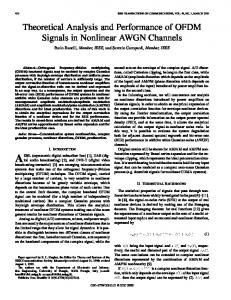
2.1 CAP Modulation The CAP modulation is one of the advanced modulation formats which can be implemented in a digital or analog form. CAP modulation is a two-dimensional (2-D) or multidimensional passband transmission signal format which looks like QAM modulation but the CAP modulation does not need local oscillator (LO) and mixer. The digital implementation of CAP-16 modulation is performed by encoding the input binary data using two PAM-4 mappers each has four-level amplitude as shown in Figure1. The mappers generate the in-phase part (X(i)) and the quadrature part (Z(i)) of the symbols, respectively [2]. The inphase X(i) and quadrature Z(i) symbols are applied to the input of SRRC shaping filters. By combining the filters' outputs, the multilevel CAP signal is obtained. S(t) =∑𝑖 𝑋(𝑖)𝑅(𝑡 − 𝑖𝑇) − 𝑍(𝑖) Ȓ(𝑡 − 𝑖𝑇)
(1)
R(t) = g(t) cos(2πfct)
(2a)
Ȓ(t) = g(t) sin(2πfct)
(2b)
Copyright © Society for Science and Education United Kingdom
11
Majidah H. Majeed and Raad S. Fyath; Performance Investigation of 112 Gb/s Hybrid Multiband CAP/QAM Schemes for Short Reach Optical Communication Systems, Transactions on Networks and Communications, Volume 4 No. 6, December (2016); pp: 10-32
Figure. 1 Block diagram of CAP signal generation.
where g(t) is the impulse response of SRRC filter and fc is the center frequency of the subband in the CAP/QAM system. The two filters R(t) and Ȓ(t) form a so named Hilbert pair. A Hilbert pair is two signals of the same magnitude response but with phase responses shifted by (π/2) radian. Equation (2) indicates that the impulse response of I and Q shaping filters is obtained from time multiplication the SRRC output with cosine and sine waveforms, respectively. The CAP modulation has many advantages, among them are i.
It increases the spectral efficiency by increasing the order of modulation and then increasing the data rate for a given transmitted bandwidth [6].
ii.
Since CAP modulation is of high bandwidth efficiency, low implementation costsand support modulation more than 2-dimensional format.CAP has been widely used in asynchronous digital subscriber link and asynchronous transfer mode local area network[2,7].
iii.
iii-It neither requires discrete Fourier transform utilized in OFDM signal generation and demodulation, nor needs complex mixer and local oscillator as the QAM used.
iv.
It needs simpler digital signal processing(DSP) implementation and does not require analog-todigital or digital-to-analog convertors.
v.
It is of excellent performance using low cost and limited bandwidth DML and vertical cavity surface-emitting lasers.
vi.
It allows high data rate.
vii.
CAP receivers have low tolerance to high frequency jitter [5].
viii.
viii-In multiband, the bandwidth is divided into smaller subbands, so CAP lowers the peak-toaverage power ratio (PAPR) [4].
2.2 Squared Root-Raised Cosine Filter The design of the shaping filters in the CAP transmitter and the receiver are based on Nyquist criterion in order to remove the inter symbol interference (ISI) between the adjacent symbols. If the lowpass transmitted signal is band limited to (W) Hertz, it can be viewed as sending a minimum of (2W) independent symbols per second through a channel represented by an ideal lowpass filter of bandwidth (W). If the ith impulse of amplitude ai is transmitted through the channel at time t = iT=(i/2W), T is the sampling time, the output of the channel is given by [8] URL: http://dx.doi.org/10.14738/tnc.46.2370
12
Transactions on Networks and Communications; Volume 4, Issue 6, December 2016
yi (t) = ai sinc [2W (t −
i )] 2W
(3)
For a sequence of impulses spaced byT = 1/ (2W), the channel y(t) = ∑𝑖 𝑦ᵢ(𝑡) = ∑𝑖 𝑎ᵢ𝑠𝑖𝑛𝑐[2𝑊(𝑡 − 𝑖/2𝑊)]
(4)
If the channel output is sampled at time tm=m/2W, the sample value is am because the sinc function equals either 1 when 𝑚 = 𝑖 or zero for 𝑚 ≠ 𝑖. Then, the mth sample value at the output of the channel is not affected by the last or the next sample values which ensures zero ISI. There are band-limited waveforms other than sinc(2Wt) that have the property of zero ISI but their zero crossings are spaced by T =1/2W seconds. These waveform have raised cosine spectrum. The pulse shaping, ISI, and the bandwidth are very important parameters in the design of telecommunication systems transmitting high data rates over limited-bandwidth channel The implementation of the required raised cosine response is obtained by splitting the filter into two parts, each one called root-raised cosine filter whose impulse response is given by h(t) =
sin 𝜋𝑡\𝑇 𝜋𝑡\𝑇
𝑐𝑜𝑠𝜋𝑟𝑡\𝑇 1−(2𝑟𝑡\𝑇)2
(5)
where T is the sampling interval and r is the filter roll-off factor. The term
𝑠𝑖𝑛 𝜋t\𝑇 𝜋𝑡\𝑇
in equation (5) ensures
that the impulse response has zero crossing and it describes an ideal lowpass filter (LPF). The second term cos(𝜋𝑟𝑡\𝑇) 1−(2𝑟𝑡\𝑇)^2
in equation (5) decays quickly with time, hence reduces the response tails and then reducing
the impact of jitter. The frequency response of the raised cosine filter is 0 ≤ |𝑓| ≤
T
1−𝑟 2𝑇
𝑇 𝜋𝑇 1−𝑟 1−𝑟 1+𝑟 H(f) = √( {1 + cos [ (|𝑓| − )]}) ≤ |𝑓| ≤ 2 𝑟 2𝑇 2𝑇 2𝑇 |𝑓| >
0
{
(6)
1+𝑟 2𝑇
To get the squared root-raised cosine (SRRC) response at the transmitter and the receiver ,the square root of the frequency response of the raised cosine filter is taken [9,10] HSRRC (f) =√𝐻(𝑓)
(7)
and the impulse response of SRRC is h(t) =
2𝑟 cos[(1+𝑟)𝜋𝑡\𝑇] 𝜋√𝑇 1−(4𝑟𝑡\𝑇)^2
sin[(1−𝑟)𝜋𝑡\𝑇]
+
2𝑟 4𝑟𝑡\𝑇 𝜋√𝑇 1−(4𝑟𝑡\𝑇)^2
(8)
The SRRC response theoretically has infinite number of taps so it has infinite attenuation in the stop band. Practically the length should be truncated to finite value. If the number of samples is reduced, the stop band attenuation will be reduced [9]. The main advantages of the roll-off factor of the SRRC filter are [9] Copyright © Society for Science and Education United Kingdom
13
Majidah H. Majeed and Raad S. Fyath; Performance Investigation of 112 Gb/s Hybrid Multiband CAP/QAM Schemes for Short Reach Optical Communication Systems, Transactions on Networks and Communications, Volume 4 No. 6, December (2016); pp: 10-32
i-
Excess in the RF bandwidth of the CAP transmitted signal bandwidth Bandwidth = (1+r) × Symbol rate
(9)
As the roll-off factor increases, the bandwidth of the CAP signal increases and its frequency response becomes closer to the frequency response of the SRRC filter. If the roll-off factor equal to zero, then the raised cosine filter reduces to the ideal LPF having rectangular spectrum. As the roll off factor becomes larger, the eye opens up, the bandwidth will not be limited and the receiver design would be easier. Although, it is better to enlarge the roll-off factor, however, for bandwidth efficiency, the roll-off factor should be small. ii-
iii-
(sinc pulse) in the impulse response of SRRC helps in extracting
timing information of the signal, because it ensures that the function transition at integer multiples of the symbol rate. Thus the bandwidth will be varied from (0.5Rs to Rs), where Rs is the symbol rate, and will be greater than the Nyquist bandwidth by a factor of (1+r). The shaping filter has an effect on the PAPR. PAPR of the RRC filters will increase with reducing excess bandwidth and increasing filter length.
3 3.1
𝑠𝑖𝑛(2𝜋𝑡\𝑇) 2𝜋𝑡
ii- The term
Operation of Multiband CAP/QAM System
System Analysis
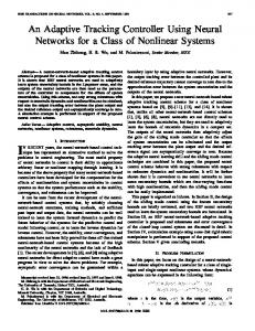
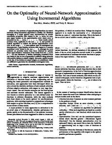
The block diagram of HMB CAP/QAM system is shown in Figure2.The performance of the system is determined by measuring the BER of each sub-band. The pseudo random binary sequence generator sequence (PRBS) produces 112 Gb/s data which is split into four paths, each of 28 Gb/s rate corresponding to one subband. The CAP signal is generated through many stages as shown in Figure 3. Each subband transmitter consists of two PAM-4 mappers to produce the in-phase (I) and quadrature components (Q) of the complex symbols of 7 Gbaud and the waveform at each mapper is set as an input to the I and Q analog shaping filters. The overall K-band system needs 2K passband filters of Hilbert pair form. The I and Q filters are formed as SRRC filters whose impulse response is given in equation (8). The choice of the center frequency should ensure orthogonally between power spectral densities of the subbands and this indicates that there is no overlap between any two adjacent subbands [5]. This means that the two I and Q filters are orthogonal. By combining the output of K subbands, the multiband CAP signal is generated as defined in equation (10). S(t)=∑𝐾 𝑘=1[∑𝑖 𝑋𝑘,𝑖 𝑔(𝑡 − 𝑖𝑇)𝑐𝑜𝑠ω𝑘,𝑐 (𝑡 − 𝑖𝑇) − ∑𝑖 𝑍𝑘,𝑖 𝑔(𝑡 − 𝑖𝑇)𝑐𝑜𝑠ω𝑘,𝑐 (𝑡 − 𝑖𝑇)
(10)
𝑋𝑘,𝑖 and 𝑍𝑘,𝑖 are the I and Q parts of the PAM-4 symbols, respectively, that are input to K subbands, ω𝑘,𝑐 =2πf𝑘,𝑐 , and f𝑘,𝑐 is the center frequency of the kth subband, and 𝑔(𝑡) is the impulse response of the SRRC filter. The generated multiband CAP signal is used to modulate the 1550 nm or 1310 nm CW laser through the Mach-Zehnder modulator (MZM). The output optical signal is launched through a SMF. The received signal is detected by a PIN photodiode (PD) and its output is split into 2K parts to be demodulated using QAM
URL: http://dx.doi.org/10.14738/tnc.46.2370
14
Transactions on Networks and Communications; Volume 4, Issue 6, December 2016
demodulators. The I and Q outputs of the SRRC matched filters,𝑦𝐴 (𝑡) 𝑎𝑛𝑑 𝑦𝐵 (𝑡), respectively, are given by [11] 𝑦𝐴 (𝑡) = 𝑦𝑘,𝐼 (𝑡) + 𝑦𝑘,𝐼𝑞 (𝑡)
(11)
where 𝑦𝑘,𝐼 (𝑡) is the in-phase or desired signal, 𝑦𝑘,𝐼𝑞 (𝑡) is the signal from quadrature channel that interfered with the desired signal. Let 𝑓(𝑡) be the impulse response of matched filter at the receiver which has a conjugate relationship in frequency domain with the SRRC shaping filters at the transmitter ( 𝑓(𝑡) = 𝑔(−𝑡)). The I and Q impulse response of the matched filters are given, respectively, by 𝑈𝑘,𝑐 (𝑡) = 𝑔(−𝑡)cos(2𝜋𝑓𝑘,𝑐 𝑡)
(12a)
̃𝑘,𝑐 (𝑡) = 𝑔(−𝑡)sin(2𝜋𝑓𝑘,𝑐 𝑡) 𝑈
(12b)
𝑦𝑘,𝐼 (𝑡)=∑𝐾 𝑘=1[∑𝑖 𝑋𝑘𝑖 𝑔(𝑡 − 𝑖𝑇)𝑐𝑜𝑠ω𝑘,𝑐 (𝑡 − 𝑖𝑇)]𝑐𝑜𝑠(ω𝑘,𝑐 𝑡 + Ө)⨂𝑓(𝑡) 𝑦𝑘,𝐼 (𝑡)=∑𝐾 𝑘=1 0.5 ∑𝑖 𝑋𝑘,𝑖 𝑔(𝑡 − 𝑖𝑇){𝑐𝑜𝑠(ω𝑘,𝑐 (2𝑡 − 𝑖𝑇) + Ө) cos(ω𝑘,𝑐 𝑖𝑇 + Ө)}⨂𝑓(𝑡) Ө is the time delay caused by the fiber link. The term c𝑜𝑠(ω𝑘,𝑐 (2𝑡 − 𝑖𝑇)+ Ө) is discarded by the lowpass matched filter. 𝑦𝑘,𝐼 (𝑡)=∑𝐾 𝑘=1{0.5 ∑𝑖 𝑋𝑘,𝑖 𝑔(𝑡 − 𝑖𝑇) cos(ω𝑘,𝑐 𝑖𝑇 + Ө)}⨂𝑓(𝑡)) 𝑦𝐼 (𝑡)=∑𝑖 𝑋𝑖 ℎ(𝑡 − 𝑖𝑇) cos ω𝑐 𝑖𝑇
(13)
where h(t) = 0.5 𝑔(𝑡)⨂𝑓(𝑡)which is the Nyquist pulse. The interference from the quadrature channel 𝑦𝑘,𝐼𝑞 (𝑡)=∑𝐾 𝑘=1[− ∑𝑖 𝑍𝑘,𝑖 𝑔(𝑡 − 𝑖𝑇)𝑠𝑖𝑛ω𝑘,𝑐 (𝑡 − 𝑖𝑇)]𝑐𝑜𝑠(ω𝑘,𝑐 𝑡 + Ө)⨂𝑓(𝑡) 𝑦𝐼𝑞 (𝑡)=∑𝑖 𝑍𝑖 ℎ(𝑡 − 𝑖𝑇) sin ω𝑐 𝑖𝑇 𝑦𝐴 (𝑡)=∑𝑖 𝑋𝑖 ℎ(𝑡 − 𝑖𝑇) cos ω𝑐 𝑖𝑇 + ∑𝑖 𝑍𝑖 ℎ(𝑡 − 𝑖𝑇) sin ω𝑐 𝑖𝑇
(14) (15)
The first term in equation (14) contains the desired transmitted signal from the k channel and the second term is the cross channel interference from Q channel. The signal 𝑦𝐵 (𝑡) can be found using the same steps followed to find 𝑦𝐴 (𝑡). The result is 𝑦𝐵 (𝑡)=∑𝑖 𝑍𝑖 ℎ(𝑡 − 𝑖𝑇) cos(ω𝑐 𝑖𝑇) − ∑𝑖 𝑋𝑖 ℎ(𝑡 − 𝑖𝑇) sin( ω𝑐 𝑖𝑇)
Copyright © Society for Science and Education United Kingdom
(16)
15
Majidah H. Majeed and Raad S. Fyath; Performance Investigation of 112 Gb/s Hybrid Multiband CAP/QAM Schemes for Short Reach Optical Communication Systems, Transactions on Networks and Communications, Volume 4 No. 6, December (2016); pp: 10-32
Figure. 2 Block diagram of HMB CAP/QAM system.
Figure. 3 Block diagram of single band CAP/QAM system.
The signals 𝑦𝐴 (𝑡) and 𝑦𝐵 (𝑡) are applied to the input port of clock recovery components to compensate the time delay between the signal at the reference port (SRRC shaping filters) and the received signals at the input port of the clock recovery components of I and Q channels. These signals will be off-line processed using DSP package, which perform many important functions such as up-sampling, DC blocking and normalization. Other essential functions and algorithms are also achieved by this DSP package among them, resampling, IQ compensation, chromatic dispersion (CD) compensation that results through the propagation along the fiber link and compensated using digital filtering. URL: http://dx.doi.org/10.14738/tnc.46.2370
16
Transactions on Networks and Communications; Volume 4, Issue 6, December 2016
The rotation of the signal constellation is corrected by the DSP package 𝑋̅=Re{[𝑦𝐴 (𝑡) + 𝑗 𝑦𝐵 (𝑡)]. 𝑒 𝑗(ω𝑘,𝑐 iT} 𝑋̅ = ∑𝑖 𝑋𝑖 ℎ(𝑡 − 𝑖𝑇)
(17)
And 𝑍̅=Im { [𝑦𝐴 (𝑡) + 𝑗 𝑦𝐵 (𝑡)]. 𝑒 𝑗(ω𝑘,𝑐 iT} 𝑍̅=∑𝑖 𝑍𝑖 ℎ(𝑡 − 𝑖𝑇)
(18)
The decision device performs soft decision on the received symbols based on the threshold boundaries of 16-QAM signal constellation in order to find the optimum decision and correct any rotation prior to applying the soft decision. Unless otherwise stated, the analysis of the system is taken for two cases back-to-back (B2B) and transmission of the optical signal over 1 km distance. In the second case, because of the dispersion in the fiber, laser line-width, and frequency offset, the received signal constellation is rotated due to the variation of the positions of the symbols in the I-Q plane. The symbols are returned back to their original positions as that in the transmitter through correlation operation performed using the decision device. The final steps that should be performed are de-mapping the detected data to I and Q parts then the decoding the two signal parts to recover the original data using the QAM decoder. The center frequency of the K subbands can be found, the first term of equation (5) which is
𝑠𝑖𝑛 𝜋t\𝑇 𝜋𝑡\𝑇
emphases that the impulse response has zero crossing, as that in the ideal low pass filter, where the bandwidth is defined as the distance from the origin to the first zero crossing. Then the cutoff frequency is defined by fc = 0.5fs . The realizable bandwidth of raised cosine filter B is Nyquist bandwidth × (1+r) B= fc =
1 2T
(1 + 𝑟)
Here fc is the center frequency of the first subband of the system. For K-band system, the kth center frequency is 1
fk,c = 2T (1 + 𝑟)(2k − 1)k=1, 2, 3, … K
(19)
3.2 Simulation Parameters Values The designed system of 112 Gb/s HMB CAP-16 system shown in Figure (2) is simulated using OptiSystem version 14.0. For K subbands, the bit rate and the symbol rate for each subband is (112/K) Gb/s and (112/ log2 M) Gbaud, respectively, where M=16, 32, or 64. For example, for 4-subband scheme, the bit rate and the symbol rate for each subband is 28 Gb/s and 7 Gbaud, respectively. The center frequencies of the subbands are calculated using equation (19) for r=0.3 and the results are summarized in Table 1. The information data of rate 112 Gb/s branch is split into four 28 Gb/s subbands which are encoded to NRZ electrical pulses of rise time and fall time of 0.25 bit. The encoded bits are mapped to I and Q parts of the complex symbols using two gray code PAM-4 mappers and the outputs are sent to the analog SRRC shaping filters. The output of K subbands are combined in order to obtain the multiband CAP signal which is used to modulate the CW laser of 1550 nm or 1310 nm wavelength through MZM modulator. The Copyright © Society for Science and Education United Kingdom
17
Majidah H. Majeed and Raad S. Fyath; Performance Investigation of 112 Gb/s Hybrid Multiband CAP/QAM Schemes for Short Reach Optical Communication Systems, Transactions on Networks and Communications, Volume 4 No. 6, December (2016); pp: 10-32
transmitted optical power propagates through a SMF link and the received optical signal is directly detected by a PIN photodiode. The electrical signal is demodulated using QAM-16demodulator. The SRRC matched filters of same properties, that is used in the transmitter, receive the demodulated signal and the output of these filters are off-line processed using DSP package for QAM-16 of symbol rate equal to bit rate divided by4. The optimum decision of each received symbol is carried out by the decision component. Finally the 4 bits QAM decoder is used to get the recovered transmitted information data. Unless otherwise stated, the parameters of the simulated system are as given in Table 2. Table 1. Center frequency of the Subbands of HMB CAP-16/QAM-16 scheme designed with r=0.3 SRRC filters.
Subband Number 1 2 3 4 5 6 7 8 9 10 11 12 13 14 15 16
Center Frequencies (GHz) 4-Subband Scheme 8-Subband Scheme 16-Subband Scheme 4.55 2.275 1.1375 13.65 6.825 3.4125 22.75 11.375 5.6875 31.85 15.925 7.9625 20.475 10.2375 25.025 12.5125 29.575 14.7875 34.125 17.0625 19.3375 21.6125 23.8875 26.1625 28.4375 30.7125 32.9875 35.2625 Table 2. Parameters values of the simulated system.
Component CW laser
Optical fiber link
Property Linewidth Wavelength Power Length Attenuation Dispersion Dispersion Slope
PIN PD
Receiver LPF
Responsively Power spectral density of the thermal noise Modulation bandwidth Cutoff frequency
Value 50 MHz 1550 nm and 1310 nm 0 dBm 1km 0.2 dB/km @ 1550 nm 0.4 dB/km @ 1310 nm 16.75 ps/nm/km @ 1550 nm 0.01 ps/nm/km @ 1310 nm 0.075 ps/sqrt(nm). km @ 1550 nm 0.09 ps/sqrt(nm). km@ 1310 nm 1 A/W 331.92×𝟏𝟎−𝟐𝟒 W/Hz
URL: http://dx.doi.org/10.14738/tnc.46.2370
Bit rate 0.75×bit rate 18
Transactions on Networks and Communications; Volume 4, Issue 6, December 2016
4
Simulation Results
The performance of HMB CAP/QAM is investigated using OptiSystem version 14.0 simulator and the obtained results of the proposed system are given in the following subsections.
4.1 Effect of Roll-off Factor 4.1.1
CAP-16/QAM-16
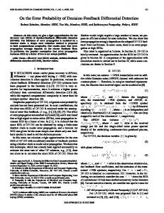
CAP-16/QAM-16 is the first scheme that is investigated and the signal constellation diagrams are obtained at the transmitter at the output of shaping filters as shown in Figure 4 for 0 dBm CW laser transmitted optical power(PT) at 1550 nm wavelength. It is clear how the discriminating of the 16 symbols becomes better with increasing r.
(a)
(b)
(d)
(e)
(c)
Figure. 4 Constellation diagrams at the output of the transmitter SRRC Shaping filter for (a) r=0.0, (b) r=0.1, (c) r= 0.2, (d) r=0.3, (e) r=0.4. The results are reported at 0 d Bm transmitted optical power and 1550 nm wavelength
At the receiver side, a PD with modulation bandwidth equal to the bit rate. Due to the dispersion of the 1km fiber link and the linewidth of the laser, the constellations at the outputs of the SRRC matched filters, are rotated by phase angle whose value varies from sub-band to another as shown in Figure 5 which clarifies this phase rotation for the four subbands at L=1 km, r=0.4, PT = 0 dBm, and λ=1550 nm. Figure 6 summarizes the RF power spectral density of CAP-16 and the detected 16 symbols in the constellation at the output of decision device which are the same asthose16 symbols in the constellation at the output of the PAM mapper in the transmitter at 0 dBm transmitting power. The comparison between the BER of 112 Gb/s four-band HMB CAP/QAM with that of single- band for each value of r is performed. It is found that improvement in the BER performance of 112 Gb/s single band and multiband is achieved by increasing r. That means by making a wider-bandwidth RF CAP signal will decrease the interference between I and Q channels. The BER of 112 Gb/s single-band CAP-16 versus CW Copyright © Society for Science and Education United Kingdom
19
Majidah H. Majeed and Raad S. Fyath; Performance Investigation of 112 Gb/s Hybrid Multiband CAP/QAM Schemes for Short Reach Optical Communication Systems, Transactions on Networks and Communications, Volume 4 No. 6, December (2016); pp: 10-32 −3
laser transmitted power at 1550 nm wavelength is illustrated in Figure 7. At 10 BER, the power improvement obtained with r=0.4 is 1.88 dBm over the case of r=0.0. The BER performance of 112 Gb/s hybrid 4- subband system is shown in Figure 7, and the improvement is of 0.75 dBm.
Figure. 5 Constellation diagrams at the output of matched filter of each subband along transmission distance L= 1 km, r=0.4, PT=0 dBm, and λ=1550 nm (a) 1stsubband,(b) 2nd subband, (c) 3rd subband, (d) 4th subband.
The corresponding curves of CAP-16/QAM-16 operating with 1310 nm CW laser are given in Figure 8 for 112 Gb/s single-band and for multiband systems. Note that the performance improvement are corresponding to 1.75 dBm for the first and approximately zero dBm for the second.
(a)
URL: http://dx.doi.org/10.14738/tnc.46.2370
20
Transactions on Networks and Communications; Volume 4, Issue 6, December 2016
(b)
(c)
Figure. 6 (a) RF power spectral density of CAP-16. Signal constellation diagrams at the output of (b) PAM mapper (c) Decision device. L= 1 km, PT =0 dBm, and λ=1550 nm.
(a) (b) Figure. 7 Performance of hybrid CAP-16/QAM-16 versus optical power for different values of r at 1550 nm wavelength. (a) Single-band system (b) 4-subband- system
(a)
(b)
Figure. 8 Performance of hybrid CAP-16/QAM-16 versus optical power for different values of r at 1310 nm wavelength. (a) Single-band system (b) 4-subband system
Copyright © Society for Science and Education United Kingdom
21
Majidah H. Majeed and Raad S. Fyath; Performance Investigation of 112 Gb/s Hybrid Multiband CAP/QAM Schemes for Short Reach Optical Communication Systems, Transactions on Networks and Communications, Volume 4 No. 6, December (2016); pp: 10-32
4.1.2
CAP-32/QAM-32
There is some difference in the implementation of CAP-32, where single QAM sequence generator with differential coding, instead of two gray code PAM sequence generators, is used at the transmitter. Figure 9 illustrates the signal constellation diagrams at different points of CAP-32/QAM-32 system operating with and PT = 0 dBm, L=1 km, and λ=1550 nm
(a)
(b)
(d)
(e)
(c)
Figure. 9 Signal constellation diagrams of CAP-32/QAM-32 at the output of(a) QAM mapper, (b) SRRC shaping filters, (c) SRRC matched filters, (d) DSP after off-line processing, (e) Decision device after optimum decision. L= 1 km, PT =0 dBm, and λ=1550 nm.
The RF power spectral density of CAP-32 at PT =0 dBm and the eye diagrams at different points of the transceiver for two lengths of the sequence of data are shown in Figure 10
(a)
URL: http://dx.doi.org/10.14738/tnc.46.2370
22
Transactions on Networks and Communications; Volume 4, Issue 6, December 2016
(b)
(c) Figure. 10 (a) RF power spectral density of CAP-32 at PT =0 dBm, and λ=1550 nm. Eye diagram at the output of SRRC shaping filters and matched filters, respectively at PT = 0dBm, and λ=1550 nm (b) sequence of 2048 bit, (c) sequence 32768 bits
Figures 11 and 12 demonstrate the effect of r on BER of 112 Gb/s single-band and multiband CAP32/QAM-32 system with two wavelengths 1550 and 1310 nm, respectively. The power improvement for each case is listed in Table 3, where it is found that single-band and multiband CAP-32 systems operating at 1310 nmis have higherimprovement than that of corresponding systems operating at 1550 nm. This is due to the negligible fiber link dispersion at the 1310 nm wavelength. The performance of CAP-16/QAM16 and CAP-32/QAM-32 systems are also compared after transmission distance 3 km with that of B2B transmission. The obtained simulation results for 1550 and 1310 nm systems are summarized in Figures 13 and 14, respectively.
(a)
(b)
Figure. 11 Variation the BER of CAP-32 with the optical power for different values of r at L= km and λ=1550 nm. (a) Single-band system (b) Four-subband system.
Copyright © Society for Science and Education United Kingdom
23
Majidah H. Majeed and Raad S. Fyath; Performance Investigation of 112 Gb/s Hybrid Multiband CAP/QAM Schemes for Short Reach Optical Communication Systems, Transactions on Networks and Communications, Volume 4 No. 6, December (2016); pp: 10-32
(a)
(b)
Figure. 12 Variation the BER of CAP-32 with the optical power for different values of r at L= km and λ=1310 nm. (a) Single-band system (b) Four-subband system Table 3. Performance improvement at BER of 𝟏𝟎−𝟑 for CAP/QAM schemes.
Scheme CAP-16/QAM-16
CAP-32/QAM-32
Number of bands Single Four Single Four Single Four Single Four
Performance Improvement(dBm) 1.88 @ 1550 nm 0.75 @ 1550 nm 1.75 @ 1310 nm 0 @ 1310 nm 0 @ 1550 nm 0.5 @ 1550 nm 0.45 @ 1310 nm 0.675@ 1310 nm
(a) (b) Figure. 13 BER of multiband CAP-16 system as a function of transmitted laser power after 3 km transmission distance. Results related to B2B transmission are also given for comparison purposes.(a) 1550 nm wavelength (b) 1310nm wavelength
URL: http://dx.doi.org/10.14738/tnc.46.2370
24
Transactions on Networks and Communications; Volume 4, Issue 6, December 2016
(a)
(b)
Figure. 14 BER of hybrid multiband CAP-32/QAM-32 as a function of transmitted laser power after 3 km transmission distance. Results related to B2B transmission are also given for comparison purposes at (a) 1550 nm wavelength (b) 1310 nm wavelength
The operation of the system at 1310 nm wavelength indicates that the power penalty is limited approximately to 1.2 dBm for CAP-16/QAM-16 and 1 dBm for CAP-32/QAM-32. While that of the 1550 nm wavelength-case is different; with increasing the transmitted power, the BER is approximately fixed at 〖10〗^(-1) for CAP-16/QAM-16 and at〖 10〗^(-2) for CAP-32/QAM-32 is fixed. This can be explained by noting that the symbol rate of CAP-32 scheme is lower than that of CAP-16. This means that the electronics and optics components will operate at lower frequency, then the possibility of error will be less. Furthermore, the eye width, which equals to the ratio of time an eye occupies to symbol time period [5] will be larger for CAP-32 system. 4.1.3
CAP-64/QAM-64
The signal constellation at different points at the trasceiver of the of CAP-64/QAM-64 scheme are as illustrated in Figure 15 while the RF power spectral density and the eye diagrams of the scheme are given in Figure 16.
(a)
(b)
(d)
(e)
(c)
Figure. 15 Signal constellation diagrams of CAP-64 scheme at the output of the (a) PAM mapper (b) SRRC shaping filters (c) SRRC matched filters (d) DSP package after off-line processing (e)Optimum decision device. L= 1 km, PT =0 dBm and λ=1550 nm.
Copyright © Society for Science and Education United Kingdom
25
Majidah H. Majeed and Raad S. Fyath; Performance Investigation of 112 Gb/s Hybrid Multiband CAP/QAM Schemes for Short Reach Optical Communication Systems, Transactions on Networks and Communications, Volume 4 No. 6, December (2016); pp: 10-32
The BER performance of 112 Gb/s single-band and 4-subband CAP-64/QAM-64 schemes with the CW laser power operating at 1550 and 1310 nm wavelengths is shown in Figures 17 and 18, respectively. Note the BER of the system is not as that of CAP-16/QAM-16 and CAP-32/QAM-32 schemes. For 4-subband system operating at at λ=1550 and 1310 nm, the BER at r=0.4 is approximately the lowest. While for single-band scheme, the lowest curve with 1310 nm wavelength is at r=0.4 and at r=0.1for 1550 nm.
(a)
(b)
(c)
Figure. 16 (a) RF power spectral density of CAP64/QAM-64scheme.Eye diagram of CAP-64/QAM64schemeatthe output of(b) SRRC shaping filters, (c) Decision device. L= 1 km, PT =0dBm and λ=1550nm
(a)
(b)
Figure. 17 Variation the BER of CAP-64/QAM-64 system with the optical power at L=1 km and λ=1550 nm. (a) Single-band system (b) Four-subband system.
URL: http://dx.doi.org/10.14738/tnc.46.2370
26
Transactions on Networks and Communications; Volume 4, Issue 6, December 2016
(a)
(b)
Figure. 18 BER performance of CAP-64/QAM-64 system as afunction of the optical laser power operating at L=1km and λ= 1310 nm. (a) Single-band system (b) Four-subband sy
4.2 Effect of Number of Subbands The investigation of 112 Gb/s hybrid 8-subband and 16-subband CAP/QAM systems is also simulated. Although the number of the electronic and the optical components increases, the ability to operate each subband at lower frequency is achieved. The RF power spectral density of CAP-16 is divided into8 subbands and 16 subbands as given in Figure19. Figures 20and 21 illustrate the signal constellation diagrams at different points in the transceiver of 8-subband and 16-subband CAP-16/QAM-16 systems, respectively. The eye diagrams at the transmitter and the receiver for both 8-subband and 16-subband systems are summarized in Figure 22.
(a)
(b) Figure. 19 RF Power spectral density for L= 1 km, PT =0 dBm and λ=1550 nm. (a) 8 –subband system (b) 16subband system.
Copyright © Society for Science and Education United Kingdom
27
Majidah H. Majeed and Raad S. Fyath; Performance Investigation of 112 Gb/s Hybrid Multiband CAP/QAM Schemes for Short Reach Optical Communication Systems, Transactions on Networks and Communications, Volume 4 No. 6, December (2016); pp: 10-32
(a)
(c)
(b)
Figure. 20 Constellation diagrams of 8-subband system at the output of the (a) SRRC shaping filter, (b) SRRC matched filter, (c) DSP package. L= 1 km, PT =0dBm and λ=1550 nm
The effect of the number of subbands on the performance of the system is also investigated. Figure 23 clarifies the comparison of the BER as a function of transmitted laser power for 112 Gb/s hybrid 4subband, 8-subband and 16-subband CAP-16/QAM-16 systems at r equals to 0.3. Note that the curve of 8-subband and 16-subband are closer to each other and the BER is higher than that of 4-subband system
(a)
(b)
(c)
(d)
Figure. 21 Constellation diagrams at the output of (a) SRRC matched filter of 1st subband (b) DSP of 1st subband (c) SRRC matched filter of 16th subband(c) DSP of 16th subband. L= 1 km, PT =0 dBm and λ=1550 nm.
URL: http://dx.doi.org/10.14738/tnc.46.2370
28
Transactions on Networks and Communications; Volume 4, Issue 6, December 2016
(a)
(c)
(b)
(d)
Figure. 22 Eye diagrams at the output of (a) SRRC shaping filter of the 8-subband system (b) decision device of the 8-subband system (c) SRRC shaping filter of the 16-subband system (d) decision device of the 16-subband. L= 1 km, PT=0 dBm, and λ=1550 nm.
Figure. 23 Effect of number of subbands on the performance the CAP-16/QAM-16 system operating with L= 1 km, PT=0 dBm, and λ=1550 nm.
4.3 Maximum Allowable Distance 4.3.1
Effect of Operating Wavelength
The maximum allowable transmission distance for a maximum BER of〖 10〗^(-3) is deduced for CAP16/QAM-16 system at 0 dBm CW laser optical power and for two operating wavelengths 1550 nm and 1310 nm. The maximum allowable distance is approximately directly proportional to the transmitted CW laser power measured in decibels for both wavelengths as shown in Figure 24. The calculated slopes are
Copyright © Society for Science and Education United Kingdom
29
Majidah H. Majeed and Raad S. Fyath; Performance Investigation of 112 Gb/s Hybrid Multiband CAP/QAM Schemes for Short Reach Optical Communication Systems, Transactions on Networks and Communications, Volume 4 No. 6, December (2016); pp: 10-32
0.2 km/dBm for 1550nm wavelength (the fiber attenuation=0.2 dB/km) and 2 km/dBm for 1310 nm wavelength (fiber attenuation = 0.4dBm/km).
(a)
(b)
Figure .24 Maximum allowable distance for 〖10〗^(-3) BER as a function of optical power for CAP16/QAM-16 system (a) 1550nm wavelength (b )1310 nm wavelength
4.3.2
Effect of Roll-off Factor
The maximum allowable distance with 112 Gb/s 4- subband CAP-16 system is deduced. Assuming 0 dBm transmitting power, the results are summarized in Table 4 for both 1550 and 1310 nm wavelengths. Table 4. Maximum allowable distance to achieve a BER of𝟏𝟎−𝟑 in CAP-16/QAM-16 system at PT=0 dBm.
Roll-off Factor
0 0.1 0.2 0.3 0.4
Maximum Allowable Distance (m) λ =1550 nm 3975 3475 3075 2550 2610
λ =1310 nm 7550 7975 7950 8000 7533
The 4-subbands CAP-16/QAM-16 system operating with 1310 nm wavelength is better than the 1550 nm counterpart since it offers longer distance with all values of r considered here. This is due to the absence of fiber group velocity dispersion at 1310 nm . 4.3.3
Effect of Modulation Order
Table 5 lists the maximum allowable distance corresponding to a BER of 〖10〗^(-3) obtained with 112 Gb/s 4-subband CAP/QAM scheme. Both 1550 nm and 1310 nm wavelength-lasers at 0 dBm transmitted power are used for simulation. Different orders of modulation of CAP/QAM at 0.2 roll-off factor are investigated. For CAP-16 and CAP-32 systems, the distance obtained with 1310 nm wavelength is approximately twice that with 1550 nm wavelength. Note that CAP-64 modulation offers shortest distance at both wavelengths.
URL: http://dx.doi.org/10.14738/tnc.46.2370
30
Transactions on Networks and Communications; Volume 4, Issue 6, December 2016
Table. 5 Maximum allowable distance for different order of modulation.
Order of modulation
CW laser wavelength (nm)
Max. Allowable Distance (m)
CAP-16/QAM-16
1310 1550 1310 1550 1310 1550
7500 3075 4500 2575 400 300
CAP-32/QAM-32 CAP-64/QAM-64
The performance of 112 Gb/s HMB and single-band CAP/QAM systems have been investigated. The systems have been implemented using analog root-raised cosine filters and a single laser operating at either 1550 or 1310 nm. The effect of filter roll-off factor r, number of subbands, and modulation order have been addressed. It has been found that the BER performance is enhanced by increasing r. At BER performance of〖 10〗^(-3), the power performance of 4-subband and single-band CAP-16/ QAM-16 systems is improved by 0.75 and 1.88 dB, respectively, at 1550 nm wavelength when r increases from 0 to 0.4. These values are to be compared with 0.5 and 0.45 dB, respectively, for CAP-32/ QAM-32 system
ACKNOWLEDGMENT One of the authors, Mrs. Majeed wants to thank the College of Engineering at University of Diyala, Iraq, for offering her the Ph.D scholarship.
REFERNCES [1]
Wei. J., Cunngham. D., Penty. R., White. I., Study of 100 Gigabit Ethernet Using Carrierless Amplitude/Phase Modulation and Optical OFDM, Journal of Lightwave Technology, vol. 31, No. 9, May 2013.
[2]
Tau. L., Ji. Y., Liu. J., Lau. A., Chi. N., and Lu. C., Advanced Modulation Formats for Short Reach Optical Communication Systems, IEEE Network, pp. 6-13, Nov./Dec. 2013.
[3]
Tao. L., Wang. Y., Gao, Y., Lau. A., Chi. N., and Lu. C., Experimental Demonstration of 10 Gb/s Multilevel Carrierless Amplitude/Phase Modulation for Short Reach Optical Communication System, Optics Express, Vol. 21, No.5, pp. 6459-6465, 2013.
[4]
Olmedo. M., Zuo. T., Jensen. J., Zhong. Q., Xu. X., Monroy. I., Multiband Carrierless Amplitude Phase Modulation for High Capacity Optical Data Links, J. Lightwave Technology, vol. 32, no, 4, pp. 798-804, Feb. 2014.
[5]
Wei. J., David. Q., Cunningham. G., Penty. R., and White. I., 100- Gb/s Hybrid Multiband CAP/QAM Signal Transmission Over a Single Wavelength, Journal of Lightwave Technology, vol. 33, No. 2, pp. 415-423, Jan. 2015.
Copyright © Society for Science and Education United Kingdom
31
Majidah H. Majeed and Raad S. Fyath; Performance Investigation of 112 Gb/s Hybrid Multiband CAP/QAM Schemes for Short Reach Optical Communication Systems, Transactions on Networks and Communications, Volume 4 No. 6, December (2016); pp: 10-32
[6]
Othman. M. B., High Dimensional Modulation and MIMO Techniques for Access Networks, PhD Thesis, Department of Photonics Engineering, DTU Fotonik, Oct. 2012.
[7]
Ray Liu. K. J., Digital Signal Processing for Multimedia Systems, University of Maryland, Japan 1999.
[8]
Ziemer. P. E., Trander. W. H., Principles of Communications Systems, Modulation, and Noise, 7th edition, Wiley, USA 2014.
[9]
Cubukce. E, Root Raised Cosine (RRC) Filters and Pulse Shaping in Communication Systems, 2012. https://ntrs.nasa.gov/archive/nasa/casi.ntrs.nasa.gov/20120008631.pdf
[10]
Inter Symbol Interference (ISI) and Root- raised Cosine (RRC) Filtering, www.complexreal.com
[11]
Abdolhamid. A. and Jhons. D., A comparison of CAP/QAM Architectures, IEEE International Symposium on Circuits and Systems, 1998.
URL: http://dx.doi.org/10.14738/tnc.46.2370
32