Transformation from CIM to PIM: A Feature-Oriented Component-Based Approach Wei Zhang1, Hong Mei2, Haiyan Zhao3, Jie Yang4 Institute of Software, School of Electronics Engineering and Computer Science, Peking University, Beijing, 100871, China {zhangw1,zhhy3,yangj4}@sei.pku.edu.cn,
[email protected]
Abstract. Model Transformation is a crucial part of Model-Driven Architecture (MDA). However, most of the current researches only focus on the transformation from PIM to PSM, and pay little attention to the CIM-to-PIM transformation. One of the results is that converting CIM to PIM will depend much on designers’ personal experience or creativity, and thus the quality of PIM can not be well controlled. This paper presents a feature-oriented component-based approach to the CIM-to-PIM transformation. In this approach, features and components are adopted as the key elements of CIM and PIM, respectively. One important characteristic of this approach is that it provides a method to decompose the n-to-n relations between features and components into two groups of 1-to-n relations. The other important characteristic is that this approach proposes a way to create components by clustering responsibilities which are operationalized from features. These two characteristics partially resolve two basic problems related to the CIM-to-PIM transformation: one is the traceability problem between CIM and PIM, the other is the problem of CIM-based PIM construction.
1 Introduction One crucial part of Model-Driven Architecture (MDA) is model transformation [16], i.e. transformation from CIM to PIM, or from PIM to PSM. In MDA, requirements for a system are modeled in CIM (Computation Independent Model). However, most of the current researches only focus on the transformation from PIM to PSM, and pay little attention to the CIM-to-PIM transformation. One possible reason of this phenomenon may be that there have been many mature technologies that can be adopted to represent PIM and PSM precisely (such as, UML [17], Software Architecture [6], CCM [15], EJB [19], and COM [14]), and many researchers believe it is possible to automate the transformation from PIM to PSM based on these technologies. Whereas, requirements modeled in CIM often lack a good structure, and it is thought to be impossible to automate the CIM-to-PIM transformation [11]. Consequently, MDA does not have enough capability to support the CIM-to-PIM transformation. One of the results is that converting CIM to PIM will depend much on designers’ personal experience or creativity, and thus the quality of PIM can not be well controlled. L. Briand and C. Williams (Eds.): MoDELS 2005, LNCS 3713, pp. 248-263, 2005. Springer-Verlag Berlin Heidelberg 2005
Transformation from CIM to PIM: A Feature-Oriented Component-Based Approach
249
In this paper, we present an approach to transforming CIM to PIM in a featureoriented component-based view. We use the feature model (consisting of a set of features and relationships between features) to structure requirements in CIM, and use the software architecture (consisting of a set of components and interactions between components) to organize elements at the PIM level. The feature model has been widely used in software reuse to capture the requirements of a set of similar systems [5, 7, 9, 10]. The entity-relationship structure and the explicit variability modeling of the feature model make it easy to be customized according to different reuse context [25]. The software architecture has long been recognized as a high-level design model to decompose a system into a set of computational elements and interactions between them [6, 1], and shows much chance of being adopted by UML2.0 [18]. Based on the research results in software reuse and software architecture, our approach mainly focuses on bridging the gap between CIM and PIM in a disciplined way, although not a fully automatic way. Generally, there are two important problems related to model transformation. One is the traceability between the source and the sink model, that is, how the elements in the source model can be traced to elements in the sink model. It is the base for model transformation. The other is the problem of the sink model’s construction, which means how the elements in the sink model are formed in transformation. It is the core of model transformation. In our approach, these two problems are incarnated into the problems concerning features and components, namely, how to trace features to components, and how to construct the software architecture based on the feature model. To resolve these two problems, our approach introduces the concept of responsibilities as the connector between features and components. A responsibility is a cohesive set of program specifications from programmers’ viewpoint, and can be used as a unit for work assignment. Tracing features to components is complex. One important reason is the complex n-to-n relations between features and components [8]. By introducing responsibilities as the connector, the n-to-n relations are decomposed into two sets of 1-to-n relations. One set contains the 1-to-n relations between features and responsibilities, indicating that a feature can be generally operationalized into several responsibilities. The other contains the 1-to-n relations between components and responsibilities, showing that a component may be assigned several responsibilities. Based on the decomposition, tracing features to components can be done in a two-step way: first operationalizing features into responsibilities, then assigning responsibilities to components. As to the software architecture’s construction, we decompose it into two subproblems, namely, component construction and interaction identification. Based on the 1-to-n relations between features/components and responsibilities, we propose a method of component construction by clustering responsibilities operationalized from features. We resolve the second sub-problem by analyzing interactions between responsibilities, and using them as the source of interactions between components. The rest of this paper is organized as follows. Basic knowledge about the feature model is presented in Section 2. Section 3 gives the feature model of a simple document editor. Section 4 shows how to decouple the n-to-n relations between features and components. Section 5 presents a method of feature model based software architecture construction. Related work is discussed in Section 6. Finally, Section 7 concludes this paper with a short summary.
250
Wei Zhang et al.
2 The Feature Model In this section, we give some basic knowledge of the feature model, with the purpose of helping readers build a clear view on feature-oriented requirements modeling. 2.1 Definition of Features Generally, the definition of a concept can be considered from two aspects: intension and extension. The intension describes the intrinsic qualities of a concept, while the extension characterizes the external embodiment. Many researches have given their definitions of features from either of the two aspects. For example, [20], [13] and [22] focus much on the intension aspect, defining a feature as a set of related requirements, while [9] and [8] emphasize the extension aspect, stating that a feature is a softwarecharacteristic in the user or customer view. In this paper, we do not introduce any novel idea about features, but just combine these two aspects and give the following definition of features. In intension, a feature is a cohesive set of individual requirements. In extension, a feature is a user/customer-visible characteristic of a software system.
Then, requirements in CIM can be partitioned into a set of features. 2.2 Refinement Refinements are binary relationships between features, which integrate features at different levels of abstraction into hierarchy structures. Hierarchy structures provide an effective way to describe complex systems. Table 1. Refinement Definitions. This show informal definitions of three kinds of refinements Refinement
Informal Definition
Decomposition
Refining a feature into its constituent features
Characterization
Refining a feature by identifying its attribute features
Specialization
Refining a general feature into a feature incorporating further details
Refinements can further be classified into three more concrete subclasses: decomposition, characterization, and specialization. Their informal definitions are given in Table 1. Some examples of them are depicted in Fig.1. The three kinds of refinement are differentiated by roles of features involved in them (see Table 2).
Transformation from CIM to PIM: A Feature-Oriented Component-Based Approach Edit
251
Legend Optional Decomposition
Copy
Cut
Paste
Characterization Specialization
Graph-move
Moving-mode
Outline-moving
Moving-constraint
Content-moving
Horizontal
Vertical
Fig. 1. Refinement Examples. This shows examples of three kinds of refinement, namely decomposition, characterization, and specialization Table 2. Roles in Refinements. This table shows the different roles played by parents and children in different kinds of refinement. In a refinement, we call the feature at a higher level of abstraction the parent, and the other feature the child Refinement
Parent-Role
Child-Role
Decomposition
Whole
Part
Characterization
Entity
Attribute
General-Entity
Specialized-Entity
Specialization
2.3 Constraint Constraints are static relationships among binding-states of features. It provides a way to verify the results of requirements customization [25] and release planning [4]. Only those results that do not violate constraints on features can be treated as candidates of valid requirements subsets or releases. By explicitly modeling constraints, the feature model possesses a good quality of customization. There are two important constraint categories, namely binary constraints, and complex constraints. Their formal definitions are given respectively in Table 3 and 4. Table 3. Binary Constraints. Binary constraints are constraints on the binding-states of two features. This shows two kinds of basic binary constraint and their formal definitions Binary Constraint requires(a, b: Feature) excludes(a, b: Feature)
Definition bound(b)
bound(a) (bound(a)
bound(b))
Where: bound(a: Feature) =def (a.binding-state = bound);
Table 4. Complex Constraints. Complex constraints are between two feature sets, which extend the parameters of binary constraints to group predicates. This shows two kinds of complex constraint and their formal definitions. Typical group predicates are listed in Table 5 Complex Constraint requires(x, y: Group-Predicate) excludes(x, y: Group-Predicate)
Definition x
y (x
y)
252
Wei Zhang et al.
Table 5. Group Predicates. Group predicates extend the parameter of the predicate bound(a: Feature) (see Table 3) to a feature set. This shows four kinds of group predicate and their formal definitions Group Predicate
Definition
single-bound(P: set Feature)
one
all-bound(P: set Feature)
a
a
multi-bound(P: set Feature)
P bound(a)
some
no-bound(P: set Feature)
a
P bound(a)
a
P bound(a) P
bound(a)
3 A Simple Document Editor In this section, we introduce the feature model of a simple document editor, which will be used in the rest of this paper as an example to demonstrate our approach. Edit
Copy Save
Cut
Paste
Un/re-do
Undo
Redo
Fig. 2. The Refinement View. This shows all features in the simple document editor and refinements between these features
The simple document editor contains 8 features. The refinement view of its feature model is shown in Fig. 2. Each feature’s description is listed in Table 6. There is one complex constraint on these features: requires (single-bound ({un/re-do}), multi-bound ({copy, cut, paste}));
Its meaning is that feature un/re-do’s availability depends on one or more binding of features copy, cut and paste. That is, if none of the three features is bound, the binding of un/re-do will be not available to users. Table 6. Descriptions of Features. Feature
Description
Edit
The collection of feature copy, cut, and paste.
Copy
Copy the selected text in the current document to the clipboard.
Cut
Cut the selected text in the current document to the clipboard.
Paste
Paste the text in the clipboard to the current position of the current document.
Un/re-do
The collection of feature undo and redo.
Undo
Undo the latest unsaved edit operation.
Redo
Redo the latest undo-ed and unsaved edit operation.
Save
Save the current document into a disk.
Transformation from CIM to PIM: A Feature-Oriented Component-Based Approach
253
4 Responsibilities In this section, we introduce the concept of responsibilities and show how responsibilities can be used to decouple the complex n-to-n relations between features and components. At the end of this section, we introduce resource containers as a special kind of responsibility containers. 4.1 Definition of Responsibilities The UML defines a responsibility as “a contract or obligation of a classifier” [17]. This definition clarifies the fact that a responsibility will be assigned to a classifier, for example, to a component in the software architecture. However, it does not tell us where a responsibility comes from, nor does it tell us the intension meaning of a responsibility. Similar to features, we define responsibilities from two aspects: In intension, a responsibility is a cohesive set of program specifications. In extension, a responsibility is a partial operationalization to certain requirements and can be used as a basic unit for work assignment to programmers.
We define responsibilities as a concept at the level of program specifications and use it to partition program specifications for work assignment. We also think it is requirements that responsibilities come from, since the final purpose of building software is to satisfy requirements. 4.2 Decoupling the n-to-n Relations Between Features and Components The purpose of introducing responsibilities is to decouple the n-to-n relations between features and components. These relations indicate that a feature may finally be implemented by a set of components, while a component may contribute to several features’ implementation. The underlying idea of the decoupling is that besides the nto-n relations, we should further point out the exact meaning of “a feature has a relation with a component”, or “a component contribute partly to a feature’s implementation”. The decoupling is based on the following pattern: Feature A has a relation with Component B. Feature A assigns Responsibility A.B to Component B.
Fig. 3 shows an example of decoupling the n-to-n relations between features and components by using this pattern.
254
Wei Zhang et al. 1.1
1
1
1
1.2
1
1.3
2.2
2
Decoupling
2
2
2.3
2
2.4
3
3 3.3
3
4
Responsibility
3.4
3
4
3.1
Fig. 3. A Decoupling Example. This shows how the n-to-n relations between features 1, 2, 3 and components 1, 2, 3, 4 are decoupled by responsibilities.
One result of the decoupling is that the original n-to-n relations between features and components are decomposed into two sets of 1-to-n relations. One set contains the 1-to-n relations between features and responsibilities. The essential of these relations is that “a feature can be generally operationalized into a set of responsibilities”. The other set contains the 1-to-n relations between components and responsibilities, and the essential of them is that “a component can be generally assigned several responsibilities”. In this sense, components can be viewed as a kind of responsibility containers. Based on the decomposition, tracing features to components can be done following two steps: first operationalizing features into responsibilities, then assigning responsibilities to components. On the other hand, the decoupling also supports tracing back from components to features. This can be achieved just by changing the deduced part of the decoupling pattern into “Component B is assigned Responsibility A.B from Feature A”. So we can see that, by introducing responsibilities, we find a more controllable way to create traceability between features and components. 4.3 Resource Containers: A Special Kind of Responsibility Containers In features’ operationalization, there are often responsibilities that consume or produce certain resources which are produced or will be consumed by other features. We introduce resource containers to structure resources related to features. Fig. 4 shows an example of resource containers in features’ operationalization. Copy
Clipboard Writes
Get-Selection
Flows
Reads
Set-Clipboard
Paste
Operationalized into Interaction Responsibility
Reads Read-Clipboard
Document
Flows
Insert
Writes
Fig. 4. An Example of Resource Containers. This shows the operationalization results of two features copy and paste in the simple document editor, and two resource containers (clipboard and document) related to the operationalization
Transformation from CIM to PIM: A Feature-Oriented Component-Based Approach
255
Resource containers can be viewed as a special kind of responsibility containers, which are assigned responsibilities of passively accepting requests from environment for resource storing, querying and retrieving. Another important role of resource containers is the medium of indirect interactions between features. An example of this can be found in Fig. 4, in which setclipboard (operationalized from copy) writes information into resource container clipboard, while read-clipboard (operationalized from paste) reads information from it. That is, feature copy and paste interact indirectly through resource container clipboard.
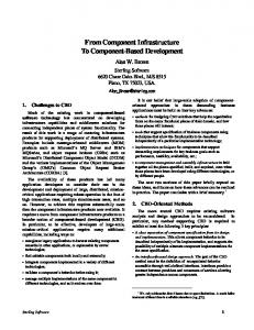
5 Constructing Software Architecture In section 4, we show how to create traceability between features and components, in the case that the feature model and software architecture have already existed. However, the real condition of transforming the feature model to the software architecture is that the later model does not exist. So, in transformation, we have to construct the software architecture based on the feature model. In this section, we show how to construct components by clustering responsibilities operationalized from features, and how to identify interactions between components by analyzing interactions between responsibilities and using them as the source of interactions between components. 5.1 An Overview An overview of transforming the feature model (CIM) to the software architecture (PIM) is depicted in Fig. 5. The principle of constructing components is based on the observation that “a component can be generally assigned several responsibilities” (see section 4). So, components can be treated as containers of responsibilities, and thus can be constructed by clustering responsibilities. Identifying interactions between components is guided by the following assumption: if two responsibilities are assigned to two different components, then any interactions between these two responsibilities will be developed into interactions between components.
1
Requirement
1..*
*
Feature
Direct-Interaction 1
1
Resource Container *
1
Operationalized-into
*
Constraint
Refinement *
The Requirement Level
1
Added Responsibility
Responsibility
The Specification Level
*
Direct-Interaction
1
1..*
Core Responsibility
*
Component Seed
1 *
1 Direct-Interaction
Fig. 5. An overview of transforming CIM to PIM.
Conceptual Component
1
256
Wei Zhang et al.
The key concepts involved in the transformation can be categorized into two levels. First is the requirements level, at which requirements are organized into the feature model. Second is the specification level. At this level, program specifications are first be partitioned into responsibilities and resource containers, with a set of interactions between them. Then, responsibilities and resource containers are clustered into a set of conceptual components and interactions between these components. In the remainder of this section, six basic aspects of the transformation are presented in six sub-sections, respectively. However, the order of these aspects is not essential. It is often the case that several of them should be considered simultaneously. 5.2 Feature Operationalization The purpose of feature operationalization is to find a programmable way to implement requirements denoted by a feature. One basic way to feature operationalization is by analyzing a feature’s description. For example, operationalizing feature copy follows this way. By analyzing the feature’s description, an experienced designer can easily operationalize it into two responsibilities (see Fig. 4): get-selection which means “getting the selected text from the current document”, and set-clipboard which means “putting the selected text into the clipboard”. When a feature has dependency on other features, its operationalization should also include responsibilities that this feature depends on other features to fulfill. For example, from the description of feature undo, we can find a requirement that only those unsaved operations can be undo-ed. Then, a responsibility inform-saved is identified, which means “when the current document is saved, feature undo should be informed”. And undo depends on feature save to fulfill this responsibility. Besides analyzing a feature’s description, we can also find dependency between features from constraints on features. For example, from the constraint: requires (single-bound ({un/re-do}), multi-bound ({copy, cut, paste})), a designer can identify responsibilities of “recording information about each operation on the current document so that any operation can be undo-ed or redo-ed later”, responsibilities which are necessary for feature un/re-do’s implementation, and which un/re-do depends on the three features copy, cut and paste to fulfill respectively. From this example, we can see the value of constraints in feature operationalization. 5.3 Resource Container Analysis Resource containers can be identified following two ways. One way is by analyzing features’ descriptions, since many resource containers have been explicitly referred in these descriptions. For instance, by analyzing the description (see Table 7) of feature copy, a designer can easily find two resource containers: clipboard and document. The other way is by analyzing constraints on features. Some resource containers are implied by constraints. For example, from the only constraint (see section 3) in the simple document editor, an experienced designer should be able to identify the resource container that stores the un/re-doing information about operations, although such a resource container are not mentioned by any features involved in the constraint. Here, we can see the value of constraints when identifying resource containers.
Transformation from CIM to PIM: A Feature-Oriented Component-Based Approach
257
5.4 Interaction Analysis Interaction analysis is a process tightly related to feature operationalization and resource container analysis. Its purpose is to identify interactions between responsibilities /and resource containers. These interactions will be used later as the source of interactions between components. We use IRR to denote the set contains all these interactions. For an interaction irr in IRR, we use irr.trigger to denote the entity that triggers irr and thus plays an active role in irr, and irr.triggee the other entity which has a passive role. At a low level, all these interactions are data flows between two entities. However, at some more semantic level, these interactions may be classified into more meaningful categories. For example, we can use write, read, produce or consume to characterize interactions between responsibilities and resource containers. In section 5.6, we will give an interaction classification at the feature level. As an example, in Fig. 4, we can see interactions between responsibilities operationalized from feature copy/paste, and interactions between these responsibilities and related resource containers. 5.5 Component Seed Creation The purpose of this step is to create seeds of components, so that responsibilities operationalized from features can be assigned to them, and conceptual components can be formed by clustering these seeds and resource containers. In our approach, we adopt a simple rule to create component seeds, that is, creating one component seed for each feature. We use ftr.cs to denote the component seed of feature ftr, cs.ftr the feature that component seed cs is created for , and cs.contains the set of responsibilities assigned to component seed cs. 5.6 Responsibility Assignment This step concerns assigning responsibilities operationalized from features to component seeds. For a responsibility r, we use r.ftr to denote the feature that r is operationalized from, and r.assignedTo the component seed that r is assigned to. Definition: Core Responsibilities; Added responsibilities A responsibility r is a core responsibility, iff r.assignedTo = r.ftr.cs. A responsibility r is an added responsibility, iff r.assignedTo
r.ftr.cs.
In other words, a core responsibility cr can be fulfilled by the feature from which that cr is operationalized (namely cr.ftr), while an added responsibility ar is a responsibility that ar.ftr has to depend on another feature to fulfill. The reason for assigning a responsibility r to a component seed other than r.ftr.cs is that the feature r.ftr depends on the data produced by feature r.assignedTo.ftr, whether directly or indirectly. For example, r.assignedTo.ftr sends an event directly to r.ftr, or r.assignedTo.ftr put some data into a resource container rc and later r.ftr reads data from rc. Fig. 6 shows responsibilities assigned to component seed copy.cs, in which getselection and set-clipboard are core responsibilities, and record-copy-URI is an added
258
Wei Zhang et al.
responsibility (where URI is the acronym for un/re-doing infomation) of copy.cs since record-copy-URI is only necessary to feature un/re-do’s implementation. 1
Copy
Operationalized into Set-Clipboard
Operationalized into
Get-Selection
Record-Copy-URI
Assigned to
…
Assigned to
Copy.cs
Un/Re-do.cs
Get-Selection
Set-Clipboard
1
1
Un/Re-do
1
… Record-Copy-URI
: Core-Responsibility
: Added-Responsibility
Fig. 6. An Example of Core and Added Responsibilities.
After responsibility assignment, the original interaction set IRR can be partitioned into three sets IIS, IBS, and ISR, where IIS denote the set of interactions inner component seeds, IBS the set of interactions between component seeds, and ISR the set of interactions between component seeds and resource containers. Due to page limitation, the formal definitions of the three sets are omitted here. We exclude interactions in IIS from our consideration since they have lost the chance to be developed into interactions between components. Depend on 1
Depend on
Invoke
ar2
Inform
arn
brn
br2
b
Operationalized into
br1
brn
br2
Assigned to
acs ar1
Flow
trigger
br1
Assigned to
bcs 1
triggee
1
a
Operationalized into
Assigned to
1
1
b
Operationalized into ar1
1
a
1
acs
br1
br2
Flow
trigger
1 bcs
triggee
br1
Fig. 7. Invoke and Inform.
Interactions in IBS can be classified into two categories: InvokeIBS and InformIBS. InvokeIBS =def {i | (i
IBS)
(i.trigger.ftr
InformIBS =def {i | (i
IBS)
(i.trigger.ftr = i.triggee.ftr)};
i.triggee.ftr)};
The meaning of this classification should be understood at the feature level. The left part in Fig. 7 depicts a typical interaction in InvokeIBS. At the low level, the interaction only models a data flow from responsibility ar1 to br1, while at the feature level, it is an interaction in which feature a sends a command to b and a depend on b to behave according to this command, called “a invokes b”. The right part in Fig. 7 depicts a typical interaction in InformIBS. At the low level, it models a data flow from responsibility br2 to br1, while at the feature level, it is an interaction in which feature a sends an event to b to indicate certain condition has been satisfied, called “a informs b”.
Copy.cs
Clipboard
Get-Slt
writes writes reads
Set-CP
writes Record Copy-URI
Cut.cs
Csm-Slt
Record Cut-URI
Set-CP
writes
writes
Paste.cs
Read-CP
Wrt-Doc
Record Paste-URI
writes
259
: Core Responsibility
Storage Document
reads consumes
: Added Responsibility
Save.cs
Read-Doc
Inform Saved Wrt-Doc informs
Un/Re-doing Info (URI)
Edit.cs
Transformation from CIM to PIM: A Feature-Oriented Component-Based Approach
clears
Clear-URI
consumes consumes
Undo.cs
Redo.cs
Undo
Redo
Un/Re-do.CS
Fig. 8. The Result of Responsibility Assignment.
Interactions in ISR can also be classified into two similar categories: InvokeISR and InformISR, where InvokeISR =def {i | (i
ISR)
(i.trigger is Feature)};
InformISR =def {i | (i
ISR)
(i.trigger is Resource-Container)};
This classification is based on the roles in an interaction i in ISR. When i.trigger is a feature, i is an interaction in which the feature depends on the resource container to fulfill a responsibility of resource storing, querying or retrieving, called “i.trigger invokes i.triggee”. When i.trigger is a resource container, i is an interaction in which the resource container tells the feature certain condition about resources has been satisfied, called “i.trigger informs i.triggee”. Fig. 8 shows the result of responsibility assignment of the simple document editor. It contains 8 component seeds corresponding to the 8 features in the feature model, 4 resource containers identified by following the two ways in sub-section 5.3, and 15 interactions between them. For clarity, interactions inner component seeds are not included in this figure. Due to page limit, the descriptions of each responsibility are not listed here. 5.7 Conceptual Component Analysis The purpose of this step is to cluster component seeds and resource containers into components in the PIM, called conceptual components (to distinguish them from components that contain platform-specific information). For a component seed or a resource container entity, we use entity.clusteredTo to denote the conceptual component that entity belongs to. Generally, there are three heuristic rules to decide which component seeds or/and resource containers should be clustered into a conceptual component. First rule is to consider the decomposition relationships (inherited from features) between component seeds and cluster a parent seed and all its children into a conceptual component. However, this rule provides no support to further cluster these children into subcomponents. The second rule is to cluster component seeds with same interaction context into a conceptual component. The interaction context of a component seed consists of all
260
Wei Zhang et al.
entities that directly interact with it. For example, in Fig. 8, component seed copy.cs, cut.cs and paste.cs have the same interaction context: {clipboard, URI, document}. So, the three components are preferred to form a conceptual component. In this example, the first and the second rules indicate the same thing from two different viewpoints. In addition, the second rule can be used to cluster children seeds into subcomponents. The third rule is to cluster a resource container with component seeds that are consumers of resources. For a resource container rc, and two component seeds p and c which play the producer and the consumer role respectively, we prefer to cluster rc with c rather than p, since rc is only necessary to feature c.ftr’s implementation and has no contribution to p.ftr’s. According to this rule, the resource container URI (see Fig. 8) should be clustered with component seed un/re-do.cs, rather than copy.cs, cut.cs and paste.cs. There may also be such a situation, in which a resource container rc has several consumers, and these consumers should not be clustered into one component. In this case, rc may need to be further decomposed. Otherwise, we can just transform rc into a conceptual component without clustering it with other entities. After clustering, only a subset of interactions in IBS and ISR are developed into interactions between conceptual components. We use IBC to denote this subset, which is defined as: IBC =def {i | (i
(IBS ISR))
(i.trigger.clusteredTo
i.triggee.clusteredTo)}
Fig. 9 shows the result of conceptual component analysis of the simple document editor. It contains 6 conceptual components identified based on the three rules above, and 6 component interactions, identified by clustering similar elements in IBC. Reads
Clipboard
Clipboard
Edit
Document
Cut
Paste
Un/Re-do
Save
> Save
Copy
Un/Re-do
Reads, Writes
Document
Reads, Modifies
Consumes
Produces
Produces
Informs Clears
URI
Storage
Storage
Fig. 9. The Result of Conceptual Component Analysis
6 Related Work CRC cards [2], RDD (Responsibility-Driven Design) [23, 24], GRASP (General Responsibility Assignment Software Patterns) [12] are three responsibility-driven object-oriented design methods, in which responsibilities are assigned to objects in a domain model. Although these methods implicitly acknowledge the tight relation between responsibilities and requirements, none of them provides enough capabilities to organize requirements, or to maintain traceability between requirements and responsibilities/objects. These methods also depend much on the correctness and completeness of a pre-created domain object model. Our approach adopts the feature model to organize requirements, and uses responsibilities as the connector between
Transformation from CIM to PIM: A Feature-Oriented Component-Based Approach
261
requirements and design elements. Our approach focuses much on system functionality instead of object behavior, and is independent of any pre-created domain model. However, these methods do suggest an object-oriented way to implement these conceptual components in our approach. UCM (Use Case Map) [3] also treats components as responsibility containers and assigns responsibilities to components. However, it doesn’t point out where to find components, but presumes the pre-existence of components. On the contrary, our approach doesn’t require the pre-existence of components. Components in our approach are constructed by clustering related responsibilities and resource containers. In addition, UCM doesn’t make a distinction between core and added responsibilities. It only focuses on the time sequence between responsibilities, and doesn’t distinguish between invoke and inform interactions. [21] presents an approach to deriving software architecture from system goals. In this approach, agents in a system are treated as components in software architecture; responsibilities (called operations) are identified from goal specifications and assigned to agents; interactions between components are identified by considering the data dependencies among them. This approach may not work well when a software system contains only a few agents. Such a problem doesn’t exist in our approach, since components in our approach are formed in a constructive way, instead of preappointed. An interesting characteristic of this approach is that it provides a set of formal patterns to ensure the correctness of goal operationaliztion, which is currently lacked in our approach.
7 Conclusions This paper presents an approach to CIM-to-PIM transformation, in which, the feature model and the software architecture are adopted as CIM and PIM, respectively. This approach introduces responsibilities as the connector between features and components, that is, a feature can be generally operationalized into a set of responsibilities, and a component can be generally assigned several responsibilities. Then, this approach proposes a method to constructing software architecture based on the feature model. In this method, features are first operationalized into responsibilities, resource containers and interactions between them, then responsibilities and resource containers are clustered to form the software architecture at the PIM level. We think this approach provides a disciplined way to CIM-to-PIM transformation, although not a fully automatic way. Future work includes the study of the issue of formal patterns in feature operationalization and component construction, applications to more complex case studies, and tool support for CIM-to-PIM transformation.
Acknowledgements The authors would like to thank the anonymous reviewers for their valuable comments and suggestions. This work is supported by the National Grand Fundamental
262
Wei Zhang et al.
Research 973 Program of China under Grant No. 2002CB312003, the National Natural Science Foundation of China under Grant No.60233010, 60125206 and 90412011, and the Beijing Natural Science Foundation under Grant No. 4052018.
References 1. 2. 3. 4.
5. 6.
7. 8. 9. 10. 11. 12. 13. 14. 15. 16. 17.
Allen, R., Garlan, D.: Formalizing Architectural Connection. In: Proceeding of 16th International Conference on Software Engineering. (1994) 71-80 Beck, K., Cunningham, W.: A Laboratory for Teaching Object-Oriented Thinking. In: OOPLSA89, SIGPLAN Notices, Vol. 24. New Orleans, Louisiana (1989) 1-6 Buhr, R.J.A.:Use Case Maps as Architectural Entities for Complex Systems. In: IEEE Transactions on Software Engineering, Vol. 24. IEEE Computer Society (1998) 11311155 Carlshamre, P., Sandahl, K., Lindvall, M., Regnell, B., Natt och Dag, J.: An Industrial Survey of Requirements Interdependencies in Software Product Release Planning. In: Proceedings of 5th IEEE International Symposium on Requirements Engineering. IEEE Computer Society (2001) 84-91. Chastek, G., Donohoe, P., Kang, K.C, Thiel, S.: Product Line Analysis - A Practical Introduction. SEI-2001-TR-001, Software Engineering Institute, Carnegie Mellon University (2001) Garlan, D., Shaw, M.: An Introduction to Software Architecture. In: Ambriola, V., Tortora, G. (eds.): Advances in Software Engineering and Knowledge Engineering. Series on Software Engineering and Knowledge Engineering, Vol. 5. World Scientific Publishing Company, Singapore (1993) 1-39 Griss, M.L., Favaro, J., d’Alessandro, M.: Integrating Feature Modeling with the RSEB. In: Proceedings of 5th International Conference on Software Reuse. IEEE Computer Society, Canada (1998) 76-85 Griss, M.L.: Implementing Product-Line Features with Component Reuse. In: Proceedings of 6th International Conference on Software Reuse. IEEE Computer Society, 2000. Kang, K.C., Cohen, S.G., Hess, J.A., Novak, W.E., Peterson, A.S.: Feature-Oriented Domain Analysis Feasibility Study. SEI-90-TR-21, Software Engineering Institute, Carnegie Mellon University (1990) Kang, K.C., Kim, S., Lee, J., Kim, K., Shin, E., Huh, M.: FORM - A Feature-Oriented Reuse Method with Domain-Specific Architecture. Annals of Software Engineering, Vol. 5. (1998) 143-168 Kleppe, A., Warmer, J., Bast, W.: MDA Explained-The Model Driven Architecture Practice and Promise. Addison Wesley (2003) Larman, C.: Apply UML and Patterns: An Introduction to Object-Oriented Analysis and Design and the Unified Process. Prentice Hall (2001) Mehta, A., Heineman, G.T.: Evolving Legacy System Features into Fine-Grained Components. In: Proceedings of the 24th International Conference on Software Engineering, IEEE Computer Society, Florida (2002) 417-427 Microsoft: Component Object Model. http://www.microsoft.com/com/. Object Management Group: CORBA Component Model, v3.0. http://www.omg.org/technology/documents/formal/components.htm. Object Management Group: MDA Guide Version 1.0.1. http://www.omg.org/mda/. (2003) Object Management Group: UML 1.5 Specification. http://www.uml.org/. (2003)
Transformation from CIM to PIM: A Feature-Oriented Component-Based Approach 18. 19. 20. 21. 22. 23. 24. 25.
263
Object Management Group: UML 2.0 Superstructure FTF convenience document. http://www.omg.org/cgi-bin/apps/doc?ptc/04-10-02.zip. (2004) Sun Microsystems: EJB 2.1 Specification. http://java.sun.com/products/ejb/. (2002) Turner, C.R., Fuggetta, A., Lavazza, L., Wolf, A.L.: A Conceptual Basis for Feature Engineering. Journal of Systems and Software, Vol. 49. (1999) 3-15 van Lamsweerde, A.: From System Goals to Software Architecture. In: Bernardo, M., Inverardi, P. (eds.): Formal Methods for Software Architectures. LNCS 2804. SpringerVerlag (2003) 25-43 Wiegers, K.E.: Software Requirements, Microsoft Press (1999) Wirfs-Brock, R., Wilkerson, B.: Object-Oriented Design: A Responsibility-Driven Approach. In: OOPLSA89, SIGPLAN Notices, Vol. 24. New Orleans, Louisiana (1989) 71-76 Wirfs-Brock, R., McKean, A.: Object Design: Roles, Responsibilities, and Collaborations. Addison Wesley (2002) Zhang, W., Zhao, H.Y., Mei, H.: A Propositional Logic-Based Method for Verification of Feature Models. In: Davies, J., Schulte, W., Barnett, M. (eds.): Formal Methods and Software Engineering. LNCS 3308. Springer-Verlag (2004) 115-130