OPERA has been used for the simulation of the transient behavior of a driven rod embedded into different earth structures. This software package is able to ...
7th Mediterranean Conference and Exhibition on Power Generation, Transmission, Distribution and Energy Conversion 7-10 November 2010, Agia Napa, Cyprus (Paper No. MED10/203)
1
Transient Behavior of Grounding Systems Embedded in Different Earth Structures Fani E. Asimakopoulou, Vassiliki T. Kontargyri, Ioannis F. Gonos and Ioannis A. Stathopulos School of Electrical and Computer Engineering, National Technical University of Athens, Athens, GR 15780, Greece
Abstract— A grounding system has to ensure personal safety with regard to the developed step and touch voltages, avert damage to properties and equipment, and achieve reliability of the power system. In this paper, the software package PC OPERA has been used for the simulation of the transient behavior of a driven rod embedded into different earth structures. This software package is able to calculate electromagnetic fields by using the Finite Element Method in order to estimate the corresponding vector and scalar potentials. Moreover, the influence of the voltage waveform on the behavior of the rod has been studied. The results demonstrate the contribution of the earth structure to the developed potential around the rod and the flexibility of the software package when simulating transient phenomena. Index Terms-- earth structure, FEM, grounding systems, potential distribution, transient behavior
I. INTRODUCTION
T
grounding system comprises an essential part of the protection of any structure (power system, building, etc.), dissipates the stroke current into the soil and reduces the damages to personnel as well as to electrical and electronic equipment. The commonly used grounding structures are single horizontal grounding wires, vertical rods, ring conductors or a suitable combination of the above mentioned structures. The behavior of a grounding system, when subjected to impulse currents, differs from its steady state behavior. Many works have been published, describing methodologies for analyzing the transient behavior of grounding systems. Earlier models proposed by Bewley [1], Sunde [2], Gupta [3], which were based on analytical methods, suffer from simplification assumptions. However, numerical methods overcome geometrical limitations and can be applied on modeling complex grounding systems. Meliopoulos [4], [5], Geri [6], Otero [7] have suggested a circuit approach for studying the transient behavior of grounding systems. Verma [8], Mazzetti [9], Velazquez [10], Grcev [11], [12], Liu[13], [14], have adopted and evolved the transmission line approach. However, the most accurate method is the electromagnetic field approach which solves full Maxwell’s equations. Finite Element Method [15]-[17], Method of Moments [18], Boundary Element Method [19], [20] or hybrid methods [21] can be used for solving electromagnetic field problems in grounding systems. HE
II. SIMULATION PROGRAM Opera-2d is a software package for electromagnetic field
analysis, which solves a wide range of electromagnetic and electrostatic applications in both XY and axisymmetric coordinate systems. This package uses the Finite Element Method to obtain solutions to partial differential equations (Poisson's, Helmholtz and Diffusion equations) that cannot be solved by analytic methods. Opera-2d can also solve electric field problems in models with conductivity and permittivity. Additionally, non-linear materials can be modeled by this program. Since much information is required before the analysis has been performed, data entry is carried out using a powerful interactive pre-processor. Using the graphical interaction within the pre-processor, the space is divided into a contiguous set of triangular elements. Once the model has been prepared, the solution is achieved using a suitable analysis module. Several modules exist for analysis of the different types of electromagnetic excitation conditions, e.g. static, transient, steady state. The analysis program iteratively determines the correct solution, including non-linear parameters, if these are modelled. The result may then be examined using a versatile interactive postprocessor. As with the pre-processor, this is predominantly controlled by interaction through a graphical menu system. Many system variables are available for examination, including potentials, currents, fields, forces, temperature. Numerical errors due to non-successful mesh definition are also analysed, so that the mesh can be refined to achieve the required accuracy [22], [23]. The transient analysis program (Opera-2d/TR) solves eddy current models where the driving currents or voltages are changing in time in a predetermined way. It can analyze the response to multiple drive functions, including a dc background field, skin effect, nonlinear materials, in both XY and axisymmetric coordinate systems [22], [23]. Opera-2d/TR solves the vector diffusion equation with the magnetic vector potential as the unknown variable. It is formed from equations ∇×H = J (1) B = µ ( H − HC ) (2)
J = σΕ Β = ∇× Α
(3) (4)
and the integration of
∂Β (5) ∂t where H is the magnetic field strength, J is the current density, B is the magnetic flux density, A is the magnetic vector potential, E is the electric field strength, µ is the ∇×Ε =
permeability and σ is the conductivity.
2
Combining the (1)-(5), the following equation has been deduced: 1 ∂A ∇ × ∇ × Α − ΗC = Js − σ (6) ∂t µ in which the current density has been split into the source ∂A . In two current, J s and the induced current, σ ∂t dimensions, only the z components of A and J s exist. Equation (6) can be simplified to: ∂A 1 (7) −∇ ⋅ ∇ × Α z − ( ∇ × Η C )z = J s − σ z µ ∂t In addition, Opera-2d/LD option solves lossy dielectric models [22], [23]. It models the behavior of devices consisting of materials with both conductive and dielectric properties under steady-state and transient conditions. In transient models, the finite element formulation is based on the assumption that inductive effects are negligible in semiconducting dielectric models, leading to the quasi-static electric formulation, the governing equations of which are [25]: ∂ ∇ ⋅ σ∇V(P, t) + ( ε∇V(P, t) ) = 0 (8) ∂t (9) ∇ ⋅ (ε∇V(P, 0)) = 0
where P denotes the space coordinates, t denotes time, V is the electric scalar potential and ε is the permittivity.
IV. SIMULATION RESULTS The arrangement is axisymmetric. Mesh generation is of essential importance for simulation by using Opera-2d. Various meshes have been examined in order to define the most appropriate for the problem. A more dense mesh has been used on the common surface of different materials and in the area around the grounding rod. Fig 2 displays the mesh within the examined regions. Moreover, the determination of the boundary conditions is equally important. Therefore, the boundary conditions have been carefully selected. In our Opera-2d simulation, the current flow equation was first solved providing the boundary conditions for the electrostatic problem, while the soil resistivity and the relative permittivity ( ε i ) were defined as presented in Table I. The double exponential function described by (10) is considered as stimulus of the grounding system:
(
V = V0 e− at − e−bt
)
(10)
The values of the parameters V0, α, b are presented in Table II. TABLE II PARAMETERS OF DOUBLE-EXPONENTIAL VOLTAGE 2nd Waveform 1st Waveform V0[kV] 1.031 1.104 α [µsec-1] 27000 7924 β [µsec-1] 5600000 400109
III. DRIVEN ROD IN A MULTI-LAYER EARTH The grounding systems consisting of a 3m length and 17.2mm diameter single driven rod buried in different soil types is simulated by using Opera-2d. The soil model adopted in this paper is similar to the one suggested by [26], [27] and is presented in Fig.1. According to this model, the soil consists of two concentric hemispheres of radii r1=5m, r2=10m. In Table I the values of each zone’s soil resistivity and permittivity for the examined cases (1, 2, 3 and 4) are shown. These values are used for the simulations.
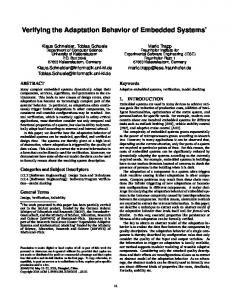
For the simulations two voltage waveforms are being used and are presented in Fig. 3. It should be noted that the computed values are normalized to 1kV peak value of the induced voltage and proportionally larger for higher voltages.
Fig. 2. The Opera-2d model with the mesh for Case 1.
Fig. 1. The geometry of the problem. TABLE I THE SOIL PARAMETERS USED FOR THE SIMULATIONS Case 1 Case 2 Case 3 Case 4
ρ1 [Ωm]
50
2000
ρ2 [Ωm]
1000
50
400
ρ3 [Ωm]
1000
400
50
1000
100
1000
ε1
200
41
ε2
16
3.5
9
41
16
41
9
ε3
9
36
9
20
R [Ω]
37.70
623.28
324.30
34.52 Fig. 3. Voltage stimuli of the grounding system.
3
In Figs. 4-7 the distribution of the potential on the soil surface is presented for each case at t=1µs when the rod is subjected to the 1st waveform.
V. ESTIMATION OF THE SURFACE POTENTIAL In Figs. 8-15 the time varying distribution of the potential on the soil up to a distance of 50m from the electrode for the examined cases for fast and slow impulse waveforms is presented.
Fig. 4. Filled zone contours of potential for Case 1 up to 20m from the electrode at t=1µs. Fig. 8. The time varying surface potential versus time and the horizontal distance from the rod for Case 1 and the 1st Voltage Waveform.
Fig. 5. Filled zone contours of potential for Case 2 up to 20m from the electrode at t=1µs. Fig. 9. The time varying surface potential versus time and the horizontal distance from the rod for Case 1 and the 2st Voltage Waveform.
Fig. 6. Filled zone contours of potential for Case 3 up to 20m from the electrode at t=1µs. Fig. 10. The time varying surface potential versus time and the horizontal distance from the rod for Case 2 and the 1st Voltage Waveform.
Fig. 7. Filled zone contours of potential for Case 4 up to 20m from the electrode at t=1µs. Fig. 11. The time varying surface potential versus time and the horizontal distance from the rod for Case 2 and the 2nd Voltage Waveform.
4
Fig. 12. The time varying surface potential versus time and the horizontal distance from the rod for Case 3 and the 1st Voltage Waveform. Fig. 16. Surface potential distribution at Tpeak for all cases.
Fig. 13. The time varying surface potential versus time and the horizontal distance from the rod for Case 3 and the 2nd Voltage Waveform.
For all the examined cases, it has been observed that at a distance of 5m and 10m, where the soil properties change, the rate of the potential’s drop also changes. In Cases 2 and 3, where the region closer to the electrode is characterized by a lower value of the soil resistivity in comparison to the second region, the potential drop is steeper than in Cases 1 and 4. Therefore, in that zone dangerous step and touch voltages are developed. Comparing Case 1 to Case 4, the influence of the third (outer) zone on the potential distribution can be examined. In Case 1 where the resistivity increases as the distance from the electrode increases, the potential drop is softer. On the other hand, in Case 4 the potential drops faster, especially as we are moving from the inner zone to the second one. This fact, also, leads to higher step and touch voltages. Surface Potential Distribution at t=1µsec for Case 1 1 Fast waveform Slow waveform
0.9
Surface Potential [kV]
0.8
Fig. 14. The time varying surface potential versus time and the horizontal distance from the rod for Case 4 and the 1st Voltage Waveform.
0.7 0.6 0.5 0.4 0.3 0.2 0.1 0
0
5
10
15 20 25 30 35 Distance from the Electrode [m]
40
45
50
Fig. 17. Surface potential distribution up to a distance of 50m for Case 1 at t=1 µsec under fast and slow impulse waveforms. Surface Potential Distribution at t=10µsec for Case 2 1 Fast waveform Slow waveform
0.9
Fig. 15. The time varying surface potential versus time and the horizontal distance from the rod for Case 4 and the 2nd Voltage Waveform.
Surface Potential [kV]
0.8 0.7 0.6 0.5 0.4 0.3 0.2
In Fig. 16 the potential distribution on the soil surface is presented for all the examined cases at the moment of peak voltage of the fast waveform.
0.1 0
0
5
10
15 20 25 30 35 Distance from the Electrode [m]
40
45
50
Fig. 18. Surface potential distribution up to a distance of 50m for Case 1 at t=10 µsec under fast and slow impulse waveforms.
5 Surface Potential Distribution at t=1µsec for Case 2
Surface Potential Distribution at t=1µsec for Case 4
1
1 Fast waveform Slow waveform
0.8
0.8
0.7
0.7
0.6 0.5 0.4 0.3
0.6 0.5 0.4 0.3
0.2
0.2
0.1
0.1
0
0
5
10
15 20 25 30 35 Distance from the Electrode [m]
40
45
Fast waveform Slow waveform
0.9
Surface Potential [kV]
Surface Potential [kV]
0.9
0
50
Fig. 19. Surface potential distribution up to a distance of 50m for Case 2 at t=1 µsec under fast and slow impulse waveforms.
0
5
Surface Potential Distribution at t=10µsec for Case 2
0.8
0.8
0.7
0.7
Surface Potential [kV]
Surface Potential [kV]
50
0.6 0.5 0.4 0.3
0.6 0.5 0.4 0.3
0.2
0.2
0.1
0.1 0
5
10
15 20 25 30 35 Distance from the Electrode [m]
40
45
50
Surface Potential Distribution at t=1µsec for Case 3 Fast waveform Slow waveform
0.9 0.8 0.7 0.6 0.5 0.4 0.3 0.2 0.1
0
5
10
15 20 25 30 35 Distance from the Electrode [m]
40
45
50
Fig. 21. Surface potential distribution up to a distance of 50m for Case 3 at t=1 µsec under fast and slow impulse waveforms. Surface Potential Distribution at t=10µsec for Case 3 1 Fast waveform Slow waveform
0.9
Fast waveform Slow waveform
0.9
1
Surface Potential [kV]
45
Surface Potential Distribution at t=10µsec for Case 4
Fig. 20. Surface potential distribution up to a distance of 50m for Case 2 at t=10 µsec under fast and slow impulse waveforms.
0.8
Surface Potential [kV]
40
1 Fast waveform Slow waveform
0.9
0
15 20 25 30 35 Distance from the Electrode [m]
Fig. 23. Surface potential distribution up to a distance of 50m for Case 4 at t=1 µsec under fast and slow impulse waveforms.
1
0
10
0.7 0.6 0.5 0.4
0
0
5
10
15 20 25 30 35 Distance from the Electrode [m]
40
45
50
Fig. 24. Surface potential distribution up to a distance of 50m for Case 4 at t=10 µsec under fast and slow impulse waveforms.
In Figs. 17-24 the potential distribution around the rod is presented for each one of the examined cases for two different waveform impulses (one fast and another slow) for two different time intervals (t=1µsec and t=10µsec). At 1µsec the fast waveform has reached its maximum value and the slow waveform is ascending. At t=10µsec the slow waveform has reached its maximum value and the fast waveform is decaying from its maximum value. Figs. 17 - 24 show that: • In those cases were the soil resistivity of the layers closer to the electrode is higher than the resistivity of the next layer (Cases 2 and 3) the potential values for t=1µsec and t=10µsec are comparable. This shows that the high resistivity region preserves the potential and prevents it from going down to zero (nullifying). • High values of resistance lead to radical fall of potential regardless of the impulse rise time. As a result, it is evident that the non-uniformity of the soil and the form of the impulse waveform affect the potential distribution on the surface of the earth. Thus, the multi-layer earth structure must be taken into account when a grounding system is designed.
0.3
VI. CONCLUSION
0.2 0.1 0
0
5
10
15 20 25 30 35 Distance from the Electrode [m]
40
45
50
Fig. 22. Surface potential distribution up to a distance of 50m for Case 3 at t=10 µsec under fast and slow impulse waveforms.
Whenever designing any grounding system the properties of the soil, its heterogeneity as well as the behavior of the grounding system under surge conditions must be taken into consideration. Simulation programs such as OPERA are proved to be an important and useful tool since any earth structure can be simulated. However, there are some
6
limitations when using OPERA 2d: only simple, axisymmetric grounding systems can be designed. Furthermore, the simulation program does not take into account the non-linear phenomena developed around the grounding system, such as soil ionization. For the simulation of more complicated grounding systems, the 3d version of the program should be used. Moreover, in that case arise some considerations regarding the solvers used by the program. The program solves either the electric or the magnetic problem. That means that either the impedance or the capacitance of the grounding system is taken into consideration. VII. ACKNOWLEDGMENT This work is funded by the Basic Research Program (PEVE). The authors want to express their sincere gratitude to the Vector Fields Company and especially to Dr. A. M. Michaelides for their kind support in the simulations.
[18]
[19]
[20]
[21]
[22] [23] [24]
[25]
VIII. REFERENCES [1] [2] [3]
[4]
[5]
[6]
[7]
[8]
[9]
[10]
[11]
[12]
[13]
[14]
[15]
[16]
[17]
L. V. Bewley: The counterpoise, G.E. Rev., Vol. 37, 1934, pp.73-81. E. D. Sunde, Earth conduction effects in transmission systems, Bell Telephone Laboratories, Incorporated, 1949. B. G. Gupta and B. Thapar: “Impulse impedance of grounding grids,” IEEE Trans. on Power Apparatus and Systems, vol. PAS-99, Nov./ Dec. 1980, pp. 2357-2362. A. P. Meliopoulos and M. G. Moharam: “Transient analysis of grounding systems,” IEEE Trans. Power App. Syst., vol. PAS-102, no. 2, Feb. 1983. A. D. Papalexopoulos and A. P. Meliopulos: “Frequency dependent characteristics of grounding systems,” IEEE Trans. Power Del., vol. 2, no. 4, Oct. 1987, pp. 1073–1081. A. Geri: “Behavior of grounding systems excited by high impulse currents: the model and its validation,” IEEE Trans. on Power Delivery, vol. 14, No 3, July 1999, pp. 2053-2059. J. Cidras, A. F. Otero, C. Garrido: “Nodal frequency analysis of grounding systems considering the soil ionization effect,” Trans. on Power Delivery, vol. 15, No 1, Jan. 2000, pp. 103-107. R. Verma and D. Mukhedkar: “Impulse to impedance of buried ground wires,” Trans. on Power Apparatus and Systems, vol. PAS99, No 5, Sep./Oct.1980, pp. 2003-2007. C. Mazzetti and G. M. Veca: “Impulse behavior of grounding electrodes,” Trans. on Power Apparatus and Systems, vol. PAS-102, No 9, 1983, pp. 3148-3156. R. Velazquez and D. Mukhedkar: “Analytical modeling of grounding electrodes transient behavior,” IEEE Trans. Power App. Syst., vol. PAS-103, no. 6, Jun. 1984, pp. 1314–1322. L. D. Grcev: “Computer analysis of transient voltages in large grounding systems,” IEEE Trans. Power Del., vol. 11, no. 2, Apr.1996, pp. 815–823. L Grcev and V. Arnautovski -Toseva: “Grounding Systems modeling for high frequencies and transients: some fundamental considerations,” presented at IEEE Bologna Power Tech conference, 2003, Bologna, Italy. Y. Liu, M. Zitnik, and R. Thottappillil: “An improved transmissionline model of grounding system,” IEEE Trans. Electromagn. Compat., vol. 43, no. 3, pp. 348–355, Aug. 2001. Y. Liu, N. Theethayi, and R. Thottappillil: “An Engineering Model for Transient Analysis of Grounding System Under Lightning Strikes: Nonuniform Transmission-Line Approach,” IEEE Trans. Power Del., vol. 20, no. 2, Apr.2005, pp. 722–730. A. Habjanic, M. Trlep, J. Pihler: “The influence of an additional substance in the trenches surrounding the grounding grid’s conductors on the grounding grid’s performance,” IEEE Transactions on Magnetics, vol. 43, No. 4, Apr. 2007, pp. 1257-1260. M. Trlep, A. Hamler, B. Hribernik: “The analysis of complex grounding systems by FEM,” IEEE Transactions on Magnetics, vol. 34, No. 5, Sept. 1998, pp. 2521-2524. L. Qi, X. Cui, Z. Zhao, H. Li” “Grounding performance analysis of the substation grounding grids by finite element frequency domain,”
[26]
[27]
IEEE Transactions on Magnetics, vol. 43, No. 4, Apr. 2007, pp. 1181-1184. Bo Zhang, Jinliang He, Jae-Bok Lee, Xiang Cui, Zhibin Zou, SugHun Chang: “Numerical analysis of the influence between large grounding grids and two-end grounded cables by the moment method coupled with circuit equations,” IEEE Transactions on Magnetics, vol. 20, No. 2, Apr. 2005, pp. 731-737. I. Colominas, F. Navarrina, M. Casteleiro: “Analysis of transferred earth potentials in grounding systems: a BEM numerical approach,” IEEE Transactions on Power Delivery, vol. 20, no. 1, Jan. 2005, pp. 339-345. I. Colominas, F. Navarrina, M. Casteleiro: “A numerical formulation for grounding analysis in stratified soils,” IEEE Transactions on Power Delivery, vol. 17, no. 2, Apr. 2002, pp. 587-595. M. Trlep, A. Hamler, M. Jesenik, B. Stumberger: “The FEM-BEM analysis of complex grounding systems,” IEEE Transactions on Magnetics, vol. 39, no. 3, May 2003, pp. 1155-1158. Opera-2d User Guide, Cobham Technical Services, Vector Fields Software, England, Version 13.014, December 2009. Opera-2d Reference Manual, Cobham Technical Services, Vector Fields Software, England, Version 13.014, December 2009. I.F. Gonos and I.A. Stathopulos: “Estimation of multi-layer soil parameters using genetic algorithms,” IEEE Trans. on Power Delivery, vol. 20, No 1, Jan. 2005, pp. 100-106. A. M. Michaelides et al.: “Parametric FEA for the design of electric insulating components: EU Project ADETEC,” presented at the 3rd Mediterranean Conference and Exhibition on Power Generation, Transmission, Distribution and Energy Conversion, Athens, Greece, 2002. J. Ma, F. Dawalibi, and W. Daily: "Analysis of Grounding Systems in soils with Hemispherical Layering," IEEE Trans. Power Delivery, vol. 8, pp. 1773-1780, 1993. F. E. Asimakopoulou, V. T. Kontargyri, I. F. Gonos and I. A. Stathopulos: “Influence of the Earth Structure to the Potential Distribution around a Driven Rod,” presented at the 6th Mediterranean Conference and Exhibition on Power Generation, Transmission, Distribution and Energy Conversion, Thessaloniki, Greece, 2008.
IX. BIOGRAPHIES Fani E. Asimakopoulou was born in Athens, Greece, in 1983. She received her Diploma in Electrical and Computer Engineering from the National Technical University of Athens, Greece, in 2006. Currently, she pursuits her Ph.D.. Her research interests include high voltages, grounding systems and electromagnetic compatibility. She is a member of the Technical Chamber of Greece. Vassiliki T. Kontargyri was born in Athens, Greece, in 1978. She received her diploma in electrical and computer engineering and her Ph.D. from National Technical University of Athens in 2002 and 2007, respectively. Her research interests concern high voltage insulators, high voltages, grounding systems and artificial neural networks. She is a member of the Technical Chamber of Greece. Ioannis F. Gonos was born on May 8, 1970 in Artemisio, Arcadia, Greece. He received his diploma in Electrical Engineering and his Ph.D. from the National Technical University of Athens in 1993 and 2002 respectively. He was a teaching assistant at the Greek Naval Academy and the Technological Education Institute of Athens (1996-2001). He is working at the High Voltage Laboratory of NTUA. His research interests concern grounding systems, insulators, high voltages, electromagnetic immunity and genetic algorithms. He is member of the Technical Chamber of Greece, the IEEE and the CIGRE. Ioannis A. Stathopulos was born in Volos, Greece in 1951. He studied in the Faculty of Electrical and Mechanical Engineering of the National Technical University of Athens (1969-1974). He carried out his doctor thesis at the Technical University of Munich (1974-1978). He become teaching assistant at the Technical University of Munich (1974-1978), production engineer in the company “Vianox–Franke” (1979-1980), teaching assistant at the National Technical University of Athens (19791983) and thereafter Lecturer (1983-1987), Assistant Professor (19871991), Associate Professor (1991-1995) and Professor (since 1995) in the High Voltage Laboratory of the NTUA. He is the author of 8 books and more than 150 papers in scientific journals and conferences proceedings. He is lead assessor of the Hellenic Accreditation Council.