Transistor-Level Based Defect-Tolerance for Reliable Nanoelectronics Aiman H. El-Maleh1, Bashir M. Al-Hashimi2, Aissa Melouki2 1
King Fahd University of Petroleum & Minerals, P.O. Box 1063, Dhahran, 31261, Saudi Arabia 2 University of Southampton, Southampton, SO17 1BJ, UK Email:
[email protected],
[email protected],
[email protected]
Abstract Nanodevices based circuit design will be based on the acceptance that a high percentage of devices in the design will be defective. In this work, we investigate a defect tolerant technique that adds redundancy at the transistor level and provides built-in immunity to permanent defects (stuck-open, stuck-short and bridges). The proposed technique is based on replacing each transistor by quaddedtransistor structure that guarantees defect tolerance of all single defects and a large number of multiple defects as validated by theoretical analysis and simulation. As demonstrated by extensive simulation results using ISCAS 85 and 89 benchmark circuits, the investigated technique achieves significantly higher defect tolerance than recently reported nanoelectronics defect-tolerant techniques (even with up to 4 to 5 times more transistor defect probability) and at reduced area overhead.
1. Introduction and Related Work With CMOS technology reaching the scaling limits, the need for alternative technologies became necessary. Nanotechnology-based fabrication is expected to offer the extra density and potential performance to take electronic circuits the next step. It is estimated that molecular electronics can achieve very high densities (1012 devices per cm2) and operate at very high frequencies (of the order of THz) [1]. Several successful nano-scale electronic devices have been demonstrated by researchers, some of the most promising being carbon naotubes (CNT) [2], silicon nanowires (NW) [3, 4], and quantum dot cells [5]. It is expected, however, that nanodevices will suffer from significantly increased permanent failure rates mainly due to the fundamental limitations of the fabrication processes that limit the yield of such devices [5]. At these nanometer scales, the small cross section areas of wires make them fragile, increasing the likelihood that they will break during assembly. Moreover, the contact area between nanowires, and between nanowires and devices depends on a few atomic-scale bonds resulting in some connections being poor and effectively unusable [6, 7]. Hewlett-Packard has fabricated 8x8 crossbar switches using molecular switches at the crosspoints [7]. They observed that only 85% of the
switches were programmable while the other 15% were defective. Therefore, the necessity to cope with intrinsic defects at the circuit level must be recognized as a key aspect of nanodevices-based designs. To implement such robustness and defect tolerance, circuit design techniques capable of absorbing a large number of defects and still be able to perform their functions need to be investigated. In the context of reliable nanoelectronics, two main approaches have been proposed: defect tolerance and defect avoidance [8]. Defect tolerance techniques are based on adding redundancy in the design to tolerate defects or faults. However, defect avoidance techniques are based on reconfigurable blocks. Recently, traditional fault tolerance techniques such as triple-modular redundancy, triple interwoven redundant logic, and quadded logic have been investigated [9] with the aim to improve the reliability of nanoelectronics design. It has been demonstrated that such techniques are capable of making nanoelectronic circuits more robust to defects. Triple-modular redundancy (TMR) is based on triplicating each gate followed by an arbitration unit deciding the correct value based on majority. The reliability of such designs is limited by that of the final arbitration unit, making the approach difficult in the context of highly integrated nanosystems [8]. A TMR circuit can be further triplicated. The obtained circuit thus has nine copies of the original module and two layers of majority gates. This process can be repeated if necessary, resulting in a technique called cascaded triple modular redundancy (CTMR) or recursive triple modular redundancy (RTMR). It is shown in [10] that using CTMR in a nanochip with large nanoscale devices would require an extremely low device error rate. It is also shown in [11] that recursive voting leads to a double exponential decrease in a circuit’s failure probability. However, a single error in the last majority gate can cause an incorrect result, hampering the technique’s effectiveness. Quadded logic [9] requires four times the circuit size. A quadded circuit implementation based on NAND gates replaces each NAND gate with a group of four NAND gates, each of which has twice as many inputs as the one it
Figure 2 (a) Transistor in original gate implementation, (b) First quadded-transistor structure, (c) Seconed quaddedtransistor structure.
Figure 1 (a) Original circuit, (b) TMR circuit, (c) Quadded logic circuit.
replaces. While quadded logic guarantees tolerance of most single errors, errors occurring at the last two stages of logic may not be corrected [9]. Figure 1 shows an example of TMR and quadded logic circuits. The previous approaches of defect-tolerance for reliable nanoelectronics have focused on adding redundancy at the functional or unit level such as TMR [10, 11], or gate level such as quadded logic [9]. In this paper, we propose adding redundancy at the transistor level and show that it provides higher tolerance than unit and gate levels and at reduced area overhead. Adding redundancy at the transistor level itself to improve reliability is not new. Indeed, in [12, 13] transistors were employed to improve the reliability of relay networks. In this work, we investigate the effectiveness of transistor-level approach when applied to ISCAS benchmark circuits, since in [12, 13] bipolar transistors were employed with very simple circuits. We investigate circuit reliability based on a quadded-transistor structure with respect to stuck-open, stuck-short and bridging defects. Furthermore, a comparison is made with recent approaches proposed for defect tolerance in nanoelectronics. IBM has recently demonstrated experimentally that carbon nanotubes can exhibit electrical characteristics that are similar to that of the state-of-the-art Si-based MOSFETs [14].
2. Proposed Defect Tolerance Technique In this work, we investigate defect tolerance based on adding redundancy at the transistor-level for electronic circuits. Our work is focused on transistor stuck-open, stuckshort and bridges between gates of transistors. A transistor is
considered defective if its expected behavior changes regardless of the type of defect causing it. In order to tolerate single-defective transistors, each transistor, A, is replaced by a quadded-transistor structure implementing either the logic function (A+A)(A+A) or the logic function (AA)+(AA), as shown in Figure 2. In both of the quaddedtransistor structures shown in Figure 2 (b) & (c), any single transistor defect (stuck-open, stuck-short, AND/OR-bridge) will not change the logic behavior, and hence the defect is tolerated. It should be observed that for nmos transistors, OR-bridge and stuck-short defects produce the same behavior while AND-bridge and stuck-open defects have the same behavior. Similarly, for pmos transistors, OR-bridge and stuck-open defects produce the same behavior while AND-bridge and stuck-short defects have the same behavior. Double stuck-open (or their corresponding bridge) defects are tolerated as long as they do not occur in any two parallel transistors (T1&T2 or T3&T4 for the structure in Figure 2(b), and T1&T2, T1&T4, T3&T2 or T3&T4 for the structure in Figure 2(c)). Double stuck-short (or their corresponding bridge) defects are tolerated as long as they do not occur in any two series transistors (T1&T3, T1&T4, T2&T3 or T2&T4 for the structure in Figure 2(b), and T1&T3 or T2&T4 for the structure in Figure 2(c)). In addition, any triple defect that does not include two parallel stuck-open defects or two series stuck-short defects or their corresponding bridging defects is tolerated. Thus, one can easily see that using either of the quadded-transistor structures, the reliability of gate implementation is significantly improved. It should be observed that the effective resistance of the quadded-transistor structures has the same resistance as the original transistor. However, in the presence of a single defect, the worst case effective resistance of the first quadded-transistor structure (Figure 2(b)) is 1.5R while that of the second quadded-transistor structure (Figure 2(c)) is 2R, where R is the effective resistance of a transistor. This occurs in the case of single stuck-open (or corresponding bridge) defects. For tolerable multiple defects, the worst case effective resistance of both structures is 2R. For this reason, the first quadded-transistor structure (Figure 2(b)) is adopted in this work.
Next, we determine the probability of circuit failure given a transistor defect probability using quadded-transistor structures. A transistor is considered defective if it does not function properly due to manufacturing defects.
Given a transistor-defect probability, P, and a circuit with N quadded-transistor structures, the probability of circuit failure and circuit reliability are N N i (− 1)i +1⎛⎜⎜ ⎞⎟⎟ Pq Pf = i ⎝ ⎠ i =1
( )
∑
N
R = 1 − Pf = 1 −
i +1 ⎛ N ⎞
∑ (− 1) i =1
( ).
⎜⎜ ⎟⎟ Pq ⎝i⎠
i
We assume in this work that circuit reliability represents the probability that the circuit will function correctly in the presence of defects. It should be observed that while the
Reliability
Given a transistor-defect probability, P, the probability of 3 1 quadded-transistor structure failure is Pq = P 2 − P 3 . 2 2 This is proved with respect to stuck-open and stuck-short defects as bridge defects have equivalent behaviors to them as explained earlier. If there are only two defective transistors in a quadded-transistor structure, then we have four possible pairs of stuck-open and stuck short defects. In all cases, only one of those pair of defects produces an error. Thus, the probability of failure in this case is 3 1 ⎛ 4⎞ 2 2 * ⎜⎜ ⎟⎟ P (1 − P )2 = P 2 (1 − P ) 2 4 ⎝ 2⎠ If we assume that three transistors are defective, then we have eight possible combinations of stuck-open and stuck short defects. In all cases, five out of those combinations produce an error. Thus, the probability of failure in this case is 5 5 ⎛ 4⎞ 3 * ⎜⎜ ⎟⎟ P (1 − P ) = P 3 (1 − P ) 2 8 ⎝ 3⎠ If four transistors are assumed defective, then in this case there will always be an error and the probability of failure is ⎛ 4⎞ 1 * ⎜⎜ ⎟⎟ P 4 = P 4 ⎝ 4⎠ Thus, the probability of quadded-transistor structure failure is 3 5 Pq = P 2 (1 − P )2 + P 3 (1 − P ) + P 4 2 2 3 2 3 4 5 3 5 4 3 = P − 3P + P + P − P + P 4 2 2 2 2 3 2 1 3 = P − P . 2 2
1 0.9 0.8
NAND2
0.7
NAND2Q NAND4
0.6
NAND4Q
0.5
NAND6
0.4
NAND6Q
0.3
NAND8
0.2
NAND8Q
0.1 0 0.0001
0.001
0.01
0.1
Prob. of transistor failure
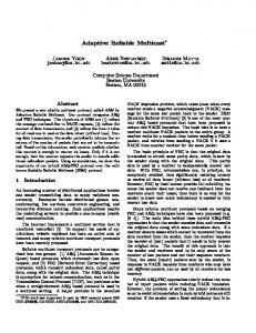
Figure 3 Gate reliability comparison between quaddedtransistor structure (Q) and complementary CMOS .
result above represents the exact circuit failure probability for stuck-open and stuck-short defects, it represents an upper bound for bridging defects. This is due to the fact that not all bridging defects that result in a faulty quadded-structure result in a faulty gate behavior. For example, AND-bridging defects between gates of transistors within the same NAND gate do not change the gate behavior regardless of their multiplicity. Similarly, OR-bridging defects between gates of transistors within the same NOR gate do not change the gate behavior regardless of their multiplicity. Figure 3 compares the reliability of several NAND gates of various inputs, 2 to 8, implemented using the quaddedtransistor structure and conventional complementary (pullup, pull-down) CMOS implementation for stuck-open and stuck-short defects. As can be seen, the reliability of gates implemented using the quadded-transistor structure is significantly higher than the reliability of conventional gate implementation. For example, for an 8-input NAND gate, with a probability of transistor failure = 10%, the probability of failure for the quadded-transistor structure-based design is 21% (and reliability is 79%), while the probability of failure for the conventional CMOS implementation is 81% (and reliability is 19%). Furthermore, as the number of inputs increases, the probability of gate failure increases and reliability decreases, as expected. The quadded-transistor structure, given in Figure 2(b), can be generalized to an N2-transistor structure, where N=2, 3,…, k. An N2-transistor structure is composed of N blocks connected in series with each block composed of N parallel transistors, as shown in Figure 4. An N2-transistor structure guarantees defect tolerance of all defects of multiplicity less than or equal to (N-1) in the structure. Hence, a large number of multiple defects can be tolerated in a circuit implemented based on these structures. Furthermore, it can be shown that the probability of failure for an N2-transistor structure is Ο P N assuming a transistor-defect probability,
( )
3.1 Stuck-Open & Stuck-Short Defect Analysis
For evaluating circuit failure probability and reliability, we adopt the simulation-based reliability model used in [9]. We compare circuit reliability based on the quaddedtransistor structure with the compared approaches in [9] including Triple Interwoven Redundancy (TIR) and Quadded logic. We use a complete test set T that detects all detectable single stuck-at faults in a circuit. We have used test sets generated by Mintest ATPG tool [16]. To compute the circuit failure probability, Fm, resulting from injecting m defective transistors, we use the following procedure: Figure 4 Defect-tolerant N2-transistor structure.
1. P (not included due to space limitation). The N2-transistor structure, for N>2, may be applied selectively for critical gates due to its increased overhead. An interesting advantage of the N2-transistor structure is that that it fits well in existing design and test methodologies. In synthesis, a library of gates implemented based on the quadded-transistor structure will be used in the technology mapping process. The same testing methodology will be used assuming testing is done at the gate level based on the single stuck-at fault model. So, the same test set derived for the original gate-level structure can be used without any change. The gate capacitance that the quadded-transistor structure induces on the gate connected to the input A is four times the original gate capacitance. This has an impact on both delay and power dissipation. However, as shown in [15], a gate with higher load capacitance has better noise rejection curves and hence is more resistant to soft errors resulting in noise glitches. While the quadded-transistor structure increases the area, this increase is less than other gate-level defect tolerance techniques as will be shown in the experimental results. As with all defect tolerance techniques, the increase in area, power and delay is traded off by more circuit reliability. This is justified given that it is predicted that nanotechnology will provide much higher integration densities, speed and power advantages.
2. 3. 4. 5. 6. 7.
Set the number of iterations to be performed, I, to 1000 and the number of failed simulations, K, to 0. Simulate the fault-free circuit by applying the test set T. Randomly inject m transistor defects. Simulate the faulty circuit by applying the test set T. If the outputs of the fault-free and faulty circuits are different, increment K by 1. Decrement I by 1 and if I is not 0 goto step 3. Failure Rate Fm =K/1000.
Assuming that every transistor has the same defect probability, P, and that defects are randomly and independently distributed, the probability of having a number of m defective transistors in a circuit with N transistors follows the binomial distribution [9] as shown below: ⎛N⎞ P (m) = ⎜⎜ ⎟⎟ P m × (1 − P) N − m ⎝m⎠ Assuming the number of transistor defects, m, as a random variable and using the circuit failure probability Fm as a failure distribution in m, the probability of circuit failure, F, and circuit reliability, R, are computed as follows [9]: N
F=
∑F
m
× P ( m)
m=0
N
R = 1− F = 1−
∑F
m
× P ( m)
m=0
3. Experimental Results To demonstrate the effectiveness of the quadedtransistor structure technique, we have performed experiments on a number of the largest ISCAS85 and ISCAS89 benchmark circuits (replacing flip-flops by inputs and outputs). Two types of permanent defects are analyzed separately: transistor stuck-open and stuck-short defects, and AND/OR bridging defects.
Figure 5 shows the reliability of some of the ISCAS85 benchmark circuits obtained both theoretically and experimentally based on the above simulation procedure and formulas for stuck-open and stuck short defects. As can be seen, there is almost identical match, clearly validating the derived theoretical results. In Figure 6, we compare the probability of circuit failure for a given number of stuck-open and stuck-short defects
1
0.8
c880t c1908t c2670t c6288t c7552t c880e c1908e c2670e c6288e c7552e
Reliability .
0.7 0.6 0.5 0.4 0.3 0.2 0.1 0 0.0001
Prob. of Failure
0.9
1 0.9 0.8 0.7 0.6 0.5 0.4 0.3 0.2 0.1 0
TIR QL QT TIR-MQT
1 0.001
0.01
0.1
Transistor Prob. Failure
Figure 5 Reliability obtained both theoretically (t) and experimentally (e) based on quadded-transistor structure and stuck-open and stuck-short defects.
between the quadded-transistor structure (QT), quadded logic (QL) [9] and TIR logic [9]. It should be observed that TIR is a generalization of TMR logic. The comparison is made based on an 8-stage cascaded half adder circuit used in [9]. TIR logic is implemented by adding a majority gate for each sum and carry-out signal at each stage. Majority gate is also implemented as a single gate. As can be seen, adding transistor-level defect tolerance generates circuits with less probability of circuit failure than those that add defect tolerance at gate level (QL) and unit level (TMR). This is in addition to smaller area overhead in terms of smaller number of transistors used. The number of transistors in the quadded-transistor structure implementation is 512, while it is 608 in TIR logic and 1024 in quadded logic. It should be observed that the total number of transistors in the circuit should be taken into account when making the comparison for a given number of defects as the percentage of injected defects varies. The probability of circuit failure for TIR and TMR logic can be significantly improved by improving the reliability of majority gates. We have implemented the majority gates in the 8-stage cascaded half adder TIR logic circuit based on the quadded-transistor structure (TIR-MQT). As shown in Figure 6, the reliability of the implemented circuit is significantly improved compared to TIR circuit at the expense of increased number of transistors (No. transistors=1280). This shows an interesting potential application of the N2-transistor structure in improving the reliability of voter-based redundancy techniques which will be more thoroughly investigated in future work. For TMR to be effective, a careful balance between the module size and the number of majority gates used needs to be made. For this reason, we focus comparison of the
3
5
7
9
11
13
15
17
19
No. of Defects
Figure 6 Comparison of circuit failure probability for an 8stage cascaded half-adder circuit for stuck-open and stuck short defects.
reliability of ISCAS benchmark circuits between quaddedtransistor structure and quadded logic. A comprehensive comparison of the probability of circuit failure between the quadded-transistor structure and the quadded logic is given in Table 1 for several percentages of injected stuck-open and stuck-short defects. For all the circuits, the quadded-transistor technique achieves significantly lower circuit failure probability than the quadded logic technique for the same and for twice the percentage of injected defects. For 10 out of 12 circuits, it achieves lower failure probability with four times the percentage of injected defects. In Table 2, we report the reliability results obtained based on the simulation procedure outlined above for the quadded-transistor structure and quadded logic approaches for several transistor defect probabilities based on stuck-open and stuck-short defects. The effectiveness of the quadded-transistor structure technique is clearly demonstrated by the results as it achieves higher circuit reliability with even 4 to 5 times more transistor defect probability. This is in addition to the observation that it requires nearly half the area of quadded logic as indicated by the number of transistors.
3.2 Bridging Defect Analysis
In order to analyze the defect tolerance of quaddedtransistor structure technique to bridging defects, the same simulation-based model was used. The experiments were performed on the same set of ISCAS circuits. The bridging defects were injected randomly between the gates of the defected transistor and one of its neighbors, located within a window of local transistors (±8 transistors). Both AND and OR bridging defects were injected equally. It should be
observed that for injecting m defective transistors due to bridges, only m/2 bridges need to be injected. Table 3 shows the results obtained for several percentages of injected bridging defects. As can be seen, the quadded-transistor technique exhibits a much lower failure probability than quadded-logic technique. Quaddedtransistor technique achieves failure rates lower than quadded-logic for the same and twice the percentage of injected bridging faults. For 0.25% of injected defects, it achieves failure rates nine times less than quadded-logic and three times less for 0.5% of injected defects in most of the circuits. It should be observed that for the same percentage of defective transistors, the failure rate for bridging defects is less than that of stuck-open and stuck-short defects. This is due to the fact that not all bridging defects will result in a faulty gate behavior.
4. Conclusion In this work, we have investigated a defect-tolerance technique based on adding redundancy at the transistor level. The proposed technique provides defect tolerance against a large number of permanent defects including stuck-open, stuck-short and bridging defects. Experimental results have demonstrated that the proposed technique provides significantly less circuit failure probability and higher reliability than recently investigated techniques based on gate level (quadded logic) and unit level (Triple modular redundancy). This improvement is achieved at less area overhead, for example 50% less transistors than quadded logic. The results have been investigated theoretically and by simulation using large ISCAS 85 and 89 benchmark circuits. Whilst the paper focused on tolerance of transistor defects, the proposed technique is capable of tolerating defects in interconnect, which is seen by many researchers as a source of unreliability in nanodevices. This can be achieved using four parallel interconnect lines to connect the driving gate to the four transistors in a quadded-transistor structure. This attractive feature adds to the credibility of the proposed approach for reliable nanoelectronics.
Acknowledgment This work is supported by King Fahd University of Petroleum & Minerals under project COE/Nanoscale/388.
References [1] M. Butts, A. DeHon, and S. C. Goldstein, "Molecular electronics: devices, systems and tools for gigagate, gigabit chips," In ICCAD, 2002, pp. 433-440. [2] T. N. A. Bachtold, P. Harley and C. Dekker, "Logic circuits with carbon nanotube transistors," Science, vol. 294, 2001, pp. 1317-1320. [3] Y. Cui and C. M. Lieber, "Functional nanoscale electronic devices assembled using silicon nanowire building blocks," Science, vol. 291, 2001, pp. 851-853. [4] Y. Huang, "Logic gates and computation from assembled nanowire building blocks," Science, vol. 294, 2001, pp. 1313-1317. [5] P. D. Tougaw and C. S. Lent. "Logical devices implemented using quantum cellular automata," J. Applied Physics, vol. 75, 1994, pp. 1818-1825. [6] Y. Chen G.-Y. Jung, D. A. A. Ohlberg, X. Li, D. R. Stewart, J. O. Jeppesen, K. A. Nielsen, J. Fraser Stoddart, and R. S. Williams,, “Nanoscale Molecular-Switch Crossbar Circuits,” Nanotechnology, vol. 14, no. 4, Apr. 2003, pp. 462-468. [7] D. Whang et al., “Large-Scale Hierarchical Organization of Nanowire Arrays for Integrated Nanosystems,” Nanoletters, vol. 3, no. 9, Sep. 2003, pp. 1255-1259. [8] Chen He, Margarida F. Jacome and Gustavo de Veciana, “A Reconfiguration-Based Defect-Tolerant Design Paradigm for Nanotechnologies,” IEEE Design & Test of Computers, JulyAugust 2005, pp. 316-326. [9] Jie Han, Jianbo Gao, Yan Qi, Pieter Jonker and José A.B. Fortes, “Toward Hardware-Redundant, Fault-Tolerant Logic for Nanoelectronics,” IEEE Design & Test of Computers, July-August 2005, pp. 328-339. [10] S. Spagocci and T. Fountain, “Fault Rates in Nanochip Devices,” Proc. Electrochemical Society, 1999, vol. 98, no. 19, pp. 582-593. [11] Darshan D. Thaker, Francois Impens, Isaac L. Chuang, Rajeevan Amirtharajah and Frederic T. Chong “Recursive TMR: Scaling Fault Tolerance in the Nanoscale Era,” IEEE Design & Test of Computers, July-August 2005, pp. 298-305. [12] E. F. Moore et al., “Reliable Circuits using Less Reliable Relays’’, J. Franklin Inst. , Oct. 1956, pp. 191-197. [13] J. J. Suran., “Use of Circuit Redundancy to Increase System Reliability’’, Int. Solid-State Circuits Conf., Feb. 1964, pp. 82-83. [14] Y. Lin, J. Appenzeller, J. Knoch, and P. Avouris, “Highperformance carbon nanotube FET with tunable polarities”, IEEE Trans. Nanotechnology, vol. 4, no. 5, Sept. 05, pp. 481-489. [15] Chong Zhao, Sujit Dey, and Xiaoliang Bai, “Soft-Spot Analysis: Targeting Compound Noise Effects in Nanometer Circuits,” IEEE Design & Test of Computers, July-August 2005, pp. 362-375. [16] I. Hamzaoglu and J. H. Patel, “Test Set Compaction Algorithms for Combinational Circuits’’, Proc. Int. Conf. Computer-Aided Design, Nov. 1998, pp. 283-289.
Table 1. Comparison of circuit failure probability between quadded-transistor structure and quadded logic approaches for stuckopen and stuck-short defects. Circuit #Trans. c880 c1355 c1908 c2670 c3540 c5315 c6288 c7552 s5378 s9234 s13207 s15850
7208 9232 13784 22672 30016 45048 40448 61600 35608 74856 103544 128016
Quadded-Transistor Structure 0.25% 0.5% 0.75% 0.015 0.023 0.030 0.047 0.067 0.095 0.085 0.136 0.081 0.166 0.212 0.257
0.060 0.082 0.115 0.188 0.238 0.341 0.307 0.441 0.282 0.510 0.625 0.697
0.135 0.176 0.248 0.375 0.457 0.614 0.576 0.732 0.521 0.791 0.888 0.936
1%
#Trans.
0.25%
0.237 0.287 0.400 0.569 0.674 0.816 0.787 0.909 0.737 0.939 0.980 0.992
13616 18304 24112 36064 46976 74112 77312 96816 59760 103488 150448 171664
0.452 0.531 0.673 0.958 0.59 0.991 0.685 0.985 1 0.999 1 1
Quadded Logic 0.5% 0.75% 0.783 0.846 0.94 0.999 0.901 1 0.962 1 1 1 1 1
0.905 0.975 0.984 1 0.996 1 0.999 1 1 1 1 1
1% 0.978 0.995 1 1 0.999 1 1 1 1 1 1 1
Table 2. Comparison of circuit reliability between quadded-transistor structure and quadded logic approaches for stuck-open and stuck-short defects. Circuit c880 c1355 c1908 c2670 c3540 c5315 c6288 c7552 s5378 s9234 s13207 s15850
Quadded-Transistor Structure #Trans. 0.0001 0.001 0.002 0.005 7208 9232 13784 22672 30016 45048 40448 61600 35608 74856 103544 128016
0.999 0.999 0.999 0.999 0.999 0.999 0.999 0.999 0.999 0.999 0.999 0.999
0.997 0.996 0.994 0.991 0.989 0.984 0.986 0.978 0.985 0.972 0.961 0.953
0.989 0.986 0.979 0.967 0.956 0.935 0.941 0.912 0.948 0.894 0.856 0.825
0.934 0.917 0.879 0.809 0.755 0.656 0.685 0.562 0.717 0.496 0.379 0.302
0.01
#Trans.
0.0001
0.767 0.713 0.596 0.427 0.327 0.185 0.222 0.101 0.263 0.061 0.023 0.008
13616 18304 24112 36064 46976 74112 77312 96816 59760 103488 150448 171664
0.979 0.975 0.975 0.904 0.981 0.853 0.971 0.874 0.811 0.821 0.518 0.576
Quadded Logic 0.001 0.002 0.822 0.765 0.755 0.350 0.805 0.227 0.718 0.292 0.134 0.140 0.008 0.009
0.005
0.01
0.283 0.187 0.261 0.001 0.237 0.001 0.024 0.000 0.001 0.000 0.000 0.000
0.042 0.008 0.001 0.000 0.000 0.000 0.000 0.000 0.000 0.000 0.000 0.000
0.651 0.575 0.558 0.112 0.614 0.034 0.465 0.077 0.015 0.001 0.000 0.000
Table 3. Comparison of circuit failure probability between quadded-transistor structure and quadded logic approaches for bridging defects. Circuit #Trans. c880 c1355 c1908 c2670 c3540 c5315 c6288 c7552 s5378 s9234 s13207 s15850
7208 9232 13784 22672 30016 45048 40448 61600 35608 74856 103544 128016
Quadded-Transistor Structure 0.25% 0.5% 0.75% 0.011 0.008 0.018 0.034 0.043 0.058 0.041 0.088 0.060 0.079 0.119 0.110
0.046 0.047 0.091 0.110 0.171 0.208 0.138 0.294 0.179 0.324 0.386 0.357
0.084 0.095 0.201 0.229 0.325 0.419 0.292 0.512 0.392 0.572 0.661 0.649
1%
#Trans.
0.25%
0.134 0.158 0.272 0.381 0.496 0.631 0.452 0.699 0.671 0.802 0.853 0.846
13616 18304 24112 36064 46976 74112 77312 96816 59760 103488 150448 171664
0.168 0.195 0.384 0.768 0.303 0.648 0.163 0.574 0.672 0.733 0.998 0.987
Quadded Logic 0.5% 0.75% 0.279 0.339 0.690 0.945 0.532 0.866 0.324 0.837 0.793 0.929 1 1
0.437 0.498 0.827 0.988 0.683 0.953 0.480 0.935 0.924 0.982 1 1
1% 0.539 0.571 0.916 1 0.803 0.984 0.588 0.973 0.940 0.995 1 1