Contributed paper OPTO-ELECTRONICS REVIEW 11(3), 227–235 (2003)
Segmentation and feature extraction for reliable classification of microcalcifications in digital mammograms A. WRÓBLEWSKA*, P. BONIÑSKI, A. PRZELASKOWSKI, and M. KAZUBEK Institute of Radioelectronics, Warsaw University of Technology, 15/19 Nowowiejska Str., 00-665 Warsaw, Poland Microcalcifications are one of more important signs enabling detection of breast cancer at an early stage. The main goal of the research was designing and realization of a system for automatic detection and classification of microcalcifications, taking advantage of the proposed automatic feature selection algorithm. The first step of the detection algorithm is to segment the individual objects: potential microcalcifications. This is achieved by applying opening by reconstruction top-hat technique and image thresholding based on approximation of an image local histogram with a probability density function of Gauss distribution. Selected features of the segmented objects are used as inputs to neural networks. The first classifier verifies the initial detection and the others assess a diagnosis of the input objects. The algorithm results are locations of suggested microcalcifications and optionally automatic diagnosis. The presented form of the system was verified in clinical tests using diagnosed databases (DDSM from the University of South Florida and own digitised database of mammograms). The achieved results are promising and comparable with other known systems. Efficiency of microcalcifications detection was up to 90%. Keywords: computer-aided diagnosis, microcalcification detection, digital mammography.
1. Introduction Currently, mammography is the most effective imaging modality in early breast cancer detection, particularly in finding nonpalpable small lesions (less than 1 cm in diameter). Early detection reduces breast cancer mortality by about 25% [1]. This reduction is possible thanks to introducing screening mammography, in which the most important goal is to capture cancerous lesions before clinical symptoms appear (in mammograms taken from patients without illness suspicions). However, interpretation of mammograms is not easy. The radiologist’s experience plays a meaningful role in the process of diagnosis. Until now no standard for description of the normal (healthy) breast model has been established. The reference during assessing a mammogram is the image of the other breast or comparison with the previous exams if available [2]. Generally, the aim of computer-aided diagnosis systems is to improve the opportunities of appropriate detection and evaluation of lesions. Within the last years several such technologically advanced approaches have been developed in mammography, i.e., Imagechecker by R2 Technology Inc. [3] and LORAD Selenia Full Field Digital Mammography System by Hologic [4] (they both received approval from the Food and Drug Administration as systems assist*e-mail:
[email protected]
Opto-Electron. Rev., 11, no. 3, 2003
ing in abnormalities detection), Second Look by CADx Inc. [5] and Mammex Tr by Scanis Inc. [6]. Among breast abnormalities there are microcalcifications that are one of more important signs enabling detection of breast cancer at early stage. Mammography is a basic examination to measure microcalcifications quality and quantity [2]. They appear as small bright spots with diameters from 0.1 to 3 mm. Miscellaneous texture, curvilinear or branched shapes are usually found within malignant microcalcifications, while sharply outlined pearl-like appearances and homogeneous texture are associated with benign objects. Detection and differentiation between malignant and benign breast lesions is a very hard task even for experts. The goal of this research was designing and realization of a simple, easy to implement and effective method for automatic detection and classification of microcalcifications. Important subtask was to propose a method of automatic feature selection. Moreover, another challenge was to compare a feature set automatically extracted to the sets known from the literature [7]. In general, the system should indicate suspicious regions with a strong likelihood of microcalcifications presence, classify the potential microcalcifications and propose the interpretation in diagnostic terms. The presented form of the system was verified in clinical tests using diagnosed databases ( [8] and own digitised database of exams collected from the Institute of Image Diagnosis in Wolski Hospital and the Institute of Radiology
A. Wróblewska
227
Segmentation and feature extraction for reliable classification of microcalcifications in digital mammograms in Grochów Hospital in Warsaw) after consultations with radiologists.
2. Method for detection and classiffication of microcalcifications A general diagram of the presented method is shown in Fig. 1. The first step of the detection algorithm is to segment the objects – potential microcalcifications. Next, the microcalcification shape and texture features are extracted. Based on those features, a classification is performed. The algorithm results are locations of the suggested microcalcifications and optionally automatic diagnosis.
Fig. 1. Schematic diagram of our CAD system for the automatic detection and classification of microcalcifications.
2.1. Detection of objects potential microcalcifications The goal of the initial detection of microcalcification objects is selection of the largest possible number of ‘true’ microcalcifications (true positives), good descriptions of their shapes and minimization of the number of false object indications (false positives). Analysis of diversified class of test images, testing different algorithms of pre-processing [9–11], and optimisation of segmentation stage [9] bring us to a formulation of the following algorithm of an object detection: • morphological operation white top-hat (to emphasise details in the source image), • determination of a threshold, • image thresholding, • grouping of segmented pixels into individual objects, • removal of individual pixels and small-size objects.
228
The algorithm finds out locations and shapes of potential microcalcification objects. The crucial task is to determine the universal method of threshold estimation. The values of filtered image above the threshold are to belong to microcalcifications. The threshold should make a compromise between a removal of the noise and indicating true microcalcifications with good descriptions of their shapes, which is very important for the object feature evaluation. However, it was not possible to obtain 100% separability between the noise and microcalcifications for more difficult cases. Thus, the threshold was chosen in the way to detect all the regions covered with microcalcifications. It means that detection of all microcalcifications from a cluster was not necessary, but detection of some of them was sufficient. The threshold determination algorithm (called thresholding with modelling a distribution – THwMD) arose from an experimental analysis of an image perception and its local statistical properties (contrast improvement) after morphological operation white top-hat (WTH). In such a filtered image there is more dark background (with a lower intensity level) and relatively small brighter fragments. Majority of healthy tissue structures – large areas with predominant low-frequency information can be regarded as the background. Similarly, the brighter regions are microcalcifications or fine details of the image (elements of sharp edges, individual pixels with high gradients). Grey-level histograms of images after WTH filtration are characterised by one big smooth peak and a very long tail. The peak appears in a low intensity range of the image intensity function, while the tail stretches along the higher intensity range. The tail covers only a little part (below 10%) of all values of the histogram. A normalised histogram of the WTH processed image can be approximated by distribution functions of probability densities (e.g., a normal distribution with a positive mean). This optimisation problem – minimisation of an error function, which is a difference between the normalized histogram and the approximating distribution – is solved by a conjugate gradient method. Such a histogram model can be described by two parameters – a mean and a standard deviation. On the basis of experiments, the universal rule of determining the threshold was established. The rule is as follows t = f + ns f ,
(1)
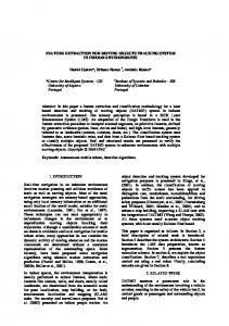
where t is the threshold, f , s f , are the mean and standard deviation of the model, respectively and n is the constant chosen experimentally. The constant equals about 3.3. An exemplary original and the image after WTH filtration as well as their grey-level histograms and the statistical model are shown in Fig. 2. This stage of histogram modelling by the statistical distribution is strongly important and recommended because of more reliable and stable universal rule established for the threshold selection. It is more difficult to establish a
Opto-Electron. Rev., 11, no. 3, 2003
© 2003 COSiW SEP, Warsaw
Contributed paper
Fig. 2. A mammogram containing microcalcifications (enlarged). (a) The original image; (b) Grey-level histogram of the original (a); (c) The image after WTH filtration; (d) Grey-level histogram of the image (c). Pixels with higher intensity cover about 3% area of the whole image. The white line denotes the chosen statistical model of the histogram. 145 – the threshold selected by THwMD.
regular relation similar to Eq. (1), having a mean and a standard deviation estimated directly from the image data set (not from a distribution model). Irregularity caused by image noise has certainly a great influence on the difficulty. In the image after WTH operation, pixels above the universal threshold are grouped together forming separate objects. Among these objects there can be microcalcifications as well as single pixels, noise and artifacts. Artifacts are small – about several pixels in area – objects, e.g., a scratch, a tiny speck of dust, which settled on a mammogram during digitisation etc. Hence, only the objects above 9 pixels in the area are considered as potential microcalcifications.
2.2. Feature set Selected features for the classification process should reflect the specificity of microcalcifications appearing in mammograms as precisely as possible. Moreover, they should emphasise the difference between benign and malignant cases. This selection of features is important to perform effective classification: to reject false indications and to distinguish malignant microcalcifications. The two approaches to feature set creation process were performed: Opto-Electron. Rev., 11, no. 3, 2003
the feature set, which was chosen subjectively on the basis of literature analysis and initial tests (proposition from Ref. 7 was selected), and feature set, which was created in automatic feature extraction process. The first step in automatic feature selection method is an extraction of a broad feature set, containing promising features found in many publications [7,12–14]. This large set will be reduced in order to find features essential and valuable for classification of microcalcifications. All evaluated features can be divided into 3 groups: • texture features, • shape features, • scalar area features. Features based on co-occurrence matrix (known also as SGLD – spatial grey level dependence matrix) plays an important role in texture features group. The SGLD matrix element pa,d(i,j) is the joint probability of the occurrence of the grey levels i and j for pixel pair separated by the distance d and at the direction a. Because of the discrete nature of digital image, the distance d is limited to integers and the angle a is limited to 0, 45, 90 and 135°. We derived features based on SGLD matrix for all angles and distances 1, 2, 4, 8, 12, 16, 20, 24, 28, and 32. Therefore, a total of 40 SGLD matrixes were derived for each region of microcalcification.
A. Wróblewska
229
Segmentation and feature extraction for reliable classification of microcalcifications in digital mammograms The shape features – seven Hu’s moments [15] and simply scalar area features like area, average grey level and standard deviation of grey level were also evaluated. All the computed features can be found in Table 1. Hence, 11 textures features (numbers of 9–13 and 15–20 from Table1) for 40 SGLD matrixes, 7 shape features (8) and 3 scalar features (1–3) make 450-dimensional feature space, which was reduced. The dimension of the feature space is very large. It is known that presence of inefficient features can deprecate classifier performance and trial to use all computed features to classification could not give good results [19]. Intuitively, it seems that performance of classification should increase with growing of number of features. However, classification performance depends on the size of a training set, the number and quality of features and the classifier complexity. The presence of inefficient features degrades classifier performance, especially when the size of training set is relatively small, and such a situation is very common in medical image recognition. For a fixed sample size, as the number of features is increased (with a corresponding increase of the number of
unknown parameters), the reliability of the parameter estimates decreases. Consequently, the performance of the classifiers may degrade with an increase in the number of the features. Moreover, classifier degradation may be caused by too perfect model fitting to imperfect real data sets (so also to intrinsic noise) when classification optimisation is made by statistical analysis of training data instead of modelling the underlying process. For fewer parameters to be estimated, such perfect match is not possible, and therefore decisions boundaries appear to be smoother. Apart from classifier performance, additional reason to reduce feature space is computational cost. Dealing with big feature vector can be time-consuming. The simplest way to choose feature set is to check all possible sets. Unfortunately, this method is unacceptable due to time cost. For example, having 450-dimensional feature space, and determined number of features to search k, the number of all possible configurations is 450!/k!(450–k)!. Even for small k, the number of all possible configurations is too large to check the sets in finite, acceptable time. Therefore, another solution of this problem is needed.
Table 1. List of features applied for classification of individual microcalcifications objects. No.
Name
Description
1
Area
2
Mean
3
Standard deviation
4
Background
5
Foreground background difference ratio (contrast between object and background)
(Mean – Background)/(Mean + Background)
6
Compactness
Perimeter of the object2/Area
7
Shape moment I
Described in Ref. 16
8
Seven Hu’s moments
Described in Refs. 15 and 17
9
Contrast
10
Entropy
11
Energy
12
Inverse different moment
13
Correlation
14
Variance
15
Sum average
16
Sum entropy
17
Sum variance
18
Difference average
19
Difference entropy
20
Difference variance
230
Size of the object Average grey level, standard deviation of grey levels, grey level of the object background
Co-occurrence matrix related features [18]
Opto-Electron. Rev., 11, no. 3, 2003
© 2003 COSiW SEP, Warsaw
Contributed paper The new feature selection method is proposed. The most important advantage of this method is the fact, that it is non-iterant, so significantly faster than iterant methods.
2.3. Image feature extraction The first step of the proposed method is template set creation. The Learning Vector Quantisation (LVQ) method is selected to create template set. LVQ is relatively new vector quantisation algorithm, proposed by Teuvo Kohonen [20,21]. The main concept of LVQ, like every vector quantisation method, lies in the approximation of input vectors by the codebook vectors mi. Usually, several codebook vectors are assigned to each class of the input values x, and x is then decided to belong to the same class to which the nearest mi belongs. Let
{
}
c = arg min x - m i , i
(1)
define the nearest mi to x, denoted by mc. The values for the mi that approximately minimise the misclassification errors in the above nearest− neighbour classification can be found as asymptotic values in the following learning process. Let x(t) be a sample of input and let the mi(t) represent sequences of the mi in the discrete-time domain. The following equations define the basic LVQ learning process m c (t + 1) = m c (t ) + a (t )[x (t ) - m c (t )] – if x and mc belong to the same class, m c (t + 1) = m c (t ) + a (t )[x (t ) - m c (t )] – if x and mc belong to different classes, m i (t + 1) = m i (t ) – for i ¹ c. The learning ratio a(t) should be contained in (0,1) and may be constant or decrease monotonically within time. In the above algorithm, it is recommended that a(t) should initially be smaller than 0.1. The above algorithm concern the basic version of LVQ called LVQ1. It is recommended as initial learning algorithm and there are some modifications of LVQ1 useful in later stages of learning process. LVQ3 is such an algorithm. The main concept remains the same as in LVQ1, however, in LVQ3 two codebook vectors mi and mj, that are the nearest neighbours to x, are now updated simultaneously. One of them must belong to the correct class and the other to a wrong class, respectively. Moreover, x must fall into a zone of values called “window”. Assume that di and dj are the Euclidean distances of x from mi and mj, respectively. Then x is defined to fall in a “window” w, if æd dj ö 1-w minçç i , ÷÷ > s, where s = 1+w èd j di ø Opto-Electron. Rev., 11, no. 3, 2003
(2)
In order to pay attention to what might happen to the location of mi there is condition that ensure that the mi continue approximating the class distributions, at least roughly. Then, the improved learning rule is defined as follows m i (t + 1) = m i (t ) - a (t )[x (t ) - m i (t )], m j (t + 1) = m j (t ) - a (t )[x (t ) - m j (t )], where mi and mj are the two closest codebook vectors to x, whereby x and mj belong to the same class, while x and mi belong to different classes, respectively; furthermore x must fall into the range mk (t + 1) = mk (t ) - ea (t )[x (t ) - mk (t )], for k Î {i,j} when x, mi and mj belongs to the same class. The useful values of e should belong to the range 0.1–0.5. The optimal value of e depends on the size of the windows, being smaller for narrower windows. The main idea of using LVQ consists in creating set of templates for each class of microcalcification: benign, malignant and false. The created set was processed by the proposed feature selection algorithm. In order to create a set of templates we select number of mammograms containing about 550 microcalcifications. On these microcalcifications the feature set presented in sec. 2.2 was computed. The computed feature set was the input data for LVQ algorithms which produced given number of template vectors for each class. On the experimental way, 15 template vectors for each class have been regarded as optimal. According to Ref. 20, the number of learning steps of LVQ algorithms was set to 50 times the total number of codebook vectors (templates). According to Ref. 20, we used LVQ 1 in initial learning process and LVQ 3 in the final stage of learning process. The computed codebook vectors were the bases for feature selection algorithm.
2.3.2. Image feature selection Our method of feature selection is based on Fisher discriminate criteria. W =
[ E(q A - q B )] 2 var q A + var q B
(3)
where qA and qB are the specified feature in the class A and B, respectively. Assuming 3 classes, calculation for all feature pairs gave 3-dimensional vector for each feature. The computed vectors were averaged and then sorted ascendancy according to their value. According to [7,12,22], we assumed that no more than 20 features would be useful. The set of 20 features admitted as most significant looks as follows: correlation, angle 0°, d = 4, W = 9.1256; sum vari-
A. Wróblewska
231
Segmentation and feature extraction for reliable classification of microcalcifications in digital mammograms ance, angle 135°, d = 2, W = 9.0156; sum average, angle 0°, d = 8, W = 9.0137; area, W = 8.9710; difference entropy, angle 90°, d = 8, W = 8.4123; inverse difference moment, angle 0°, d = 4, W = 8.2191; energy, angle 90°, d = 8, W = 7.7815; inertia, angle 135°, d = 16, W = 7.6186, sum variance, angle 0°, d = 4, W = 7.3189; sum average, angle 90°, d = 16, W = 7.1190; average grey level, W = 7.0129; difference entropy, angle 45°, d = 12, W = 6.9902; correlation, angle 135°, d = 8, W = 6.7172; difference variance, angle 45°, d = 8, W = 6.3198; difference entropy, angle 90°, d = 4, W = 6.2150; sum variance, angle 90°, d = 12, W = 5.8160; energy, angle 0°, d = 8, W = 5.6220; inverse difference moment, angle 45°, d = 2, W = 5.4498; sum variance, angle 135°, d = 8, W = 5.2596; sum average, angle 0°, d = 8, W = 5.1197. The obtained feature set was verified in respect of usefulness for classification. Starting from the first 10 features, we added following features and verified efficiency of classification with the given feature set. The best results were achieved for the feature set containing the first 16 selected features. Adding the following features made the classification results a bit worse. For comparison, feature set known from the literature [7], was evaluated also. These features are also listed in Table 1 (numbers of features: 1–7, 8 – I Hu’s moment, 9–14, 16). SGLD features are computed as an average from 4 SGLD matrixes (for angles of 0, 45, 90, 135° and a distance 1). It gives 15 subjectively selected features altogether.
2.4. Classification Similarly as in many publications about the classification of pathologies shown in mammograms [7,12,22], a multilayer feedforward backpropagation neural network with sigmoidal activation function was implemented. The number of input layer neurons was the same as a size of feature vector. The number of hidden layer neurons was experimentally set to 6 and number of output neurons was set ac-
cordingly to the number of recognized classes. The learning process parameters coming from w kij (t ) = mw kij (t - 1) + hDw kij , where w kij (t ) is the weight of link of the neuron i from the layer k-1 with the neuron j from the layer k. In experimental way, the following values were evaluated: h = 0.3 and µ = 0.2.
3. Experimental results The tests were divided into 2 stages. The first part concerns subjective tests of the initial detection of potential microcalcifications and another one focused on the classification using the two selected feature sets. The subjective tests were performed by two experts in image processing and two experts in radiology from the Institute of Image Diagnosis in Wolski Hospital. Radiologists’ suggestions were used regarding microcalcification shapes and their occurrence terms. The initial detection of potential microcalcifications was optimised with regard to influence of image pre-processing, size and shape of structuring element in WTH filtration, number of iterations of this filtration, type of probability distribution approximating histogram of an image after WTH filtration, constant “n” in Eq. (1), processing of a binary image after thresholding. The chosen parameters guarantee optimal results. The optimisation process was carried out using about 50 mammograms (containing microcalcifications of different subtlety and type) from DDSM. The obtained results were compared with the results of the initial detection performed on our own digitised database (containing over 200 selected and diagnosed mammograms). However, in order to make detection results fully reliable and to claim definite statements, it is necessary to carry out tests using a bigger data set and with a greater participation of radiologists. Exemplary result images with potential microcalcifications indicated automatically are shown in Figs. 3, 4, and 5.
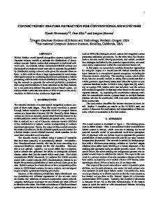
Fig. 3. A cluster of malignant microcalcifications, enlarged by 150%. (a) The original; (b) Diagnosed original – External contours of microcalcifications are denoted (manually); (c) The detection results: Microcalcifications on the original image background. Lack of false indications, one object (particularly weak visible one) is not detected.
232
Opto-Electron. Rev., 11, no. 3, 2003
© 2003 COSiW SEP, Warsaw
Contributed paper
Fig. 4. Benign large microcalcifications (above 0.5 mm in diameter), enlarged by 150%. (a) The original; (b) Diagnosed original – External contour of microcalcifications are denoted (manually); (c) The result of detection. Lack of false indications.
Fig. 5. A cluster of malignant microcalcifications. (a) The original; (b) The result of detection. Some false indications are visible along bright fibres (white arrows). Black circles denote microcalcifications that are not detected.
A set of 35 diagnosed digital mammograms (about 550 microcalcification objects of different type and subtlety) from diagnosed DDSM was applied to learn and test the neural network. The microcalcification objects were determined by the presented method of initial detection. The learning and test sets were separated. Tests for 3 network types were performed: • TRUE/FALSE – the network indicates if its input objects are “true” microcalcifications,
• BENIGN/MALIGNANT – the network suggests diagnosis only for ‘true’ microcalcifications,
• BENIGN/MALIGNANT/FALSE – the network differ-
entiates between benign, malignant and false objects. Subjectively and automatically selected features were tested. Classification results for the test set with automatically detected objects are shown in Table 2. For the automatically selected features, the best results were obtained for feature set containing the first 14 features from the selected 20.
Table 2. Obtained classification results for the test set. A type of a result
True/False
Benign/Malignant
Benign/Malignant/False
Subjectively selected features
90%
74%
68%
Automatically extracted features
89%
76%
70%
Opto-Electron. Rev., 11, no. 3, 2003
A. Wróblewska
233
Segmentation and feature extraction for reliable classification of microcalcifications in digital mammograms Table 3. Distributions of wrong neural network diagnoses for subjectively selected features. Reference diagnosis of microcalcification object
Neural network diagnosis
Wrong answers (percent)
True
False
65%
False
True
Table 4. Distributions of wrong neural network diagnoses for automatically selected features. Reference diagnosis of microcalcification object
Neural network diagnosis
Wrong answers (percent)
True
False
59%
35%
False
True
41%
Benign
77%
Malignant
Benign
64%
Malignant
23%
Benign
Malignant
36%
Malignant
Benign
35%
Malignant
Benign
13%
Malignant
False
22%
Malignant
False
17%
Benign
Malignant
15%
Benign
Malignant
16%
Benign
False
14%
Benign
False
21%
False
Malignant
8%
False
Malignant
19%
False
Benign
6%
False
Benign
15%
Malignant Benign
The distributions of wrong answers for both methods of feature selection are presented in Tables 3 and 4, respectively. Based on the above results, the proposed method for the detection and classification of microcalcifications allows obtaining a significant efficacy in differentiation between microcalcifications and false indications for both used feature sets (close to 90%). Generally, the results obtained with automatically selected features were slightly better. However, for true/false classification the subjectively selected feature set was a bit better. The automatic diagnosis results confirm correctness of the applied scheme of detection and classification and the particular solutions. Nevertheless, the optimisation work should be continued so that the method gives better results (which can be used by radiologists) while diagnosing the microcalcification malignancy.
4. Conclusions The original achievement of this research is a design and a realization of the THwDM algorithm. It is a modification of a solution from Ref. 9 which allows obtaining a better selection of potential microcalcifications. The proposed feature selection algorithm, based on dictionary vectors provided by LVQ, and Fisher discriminate criteria, proved its usefulness. The features obtained by the proposed method give overall classification results comparable with features taken from references [7,12–14]. Moreover, the distributions of wrong answers are better for the automatically selected features than the subjectively se-
234
lected ones. It makes fewer errors of real malignant cases, as is indicated in Tables 3 and 4. The results of the initial detection for our own database and DDSM are comparable. This confirms (verifies) a generality of the proposed method of segmentation, feature selection and classification. Initial radiologists’ assessments show real benefit while exploiting the presented system, mainly because of improvement of diagnosis objectivity. Physicians also confirm the usefulness of the initial microcalcification detection in evaluation of microcalcification shape and size changes in time (having mammograms taken within a period of time). It is essential as regards the assessment of malignancy of progressive lesions.
References 1. Mammography in Breast Cancer Diagnosis, Bel Corp, Warsaw, 1998. (in Polish) 2. A. Przelaskowski and P. Surowski, “Methods of medical image data optimisation applied to archiving and telemedical transmission”, Research Project of the State Committee for Scientific Research No. 7T11E03920 (2002). (in Polish). 3. http://www.r2tech.com 4. http://www.lorad.com/selenia.html 5. http://www.cadxmed.com/products/second_look_ad/ 6. http://www.scanis.com/products/index.html 7. S. Yu and L. Guan, “A CAD system for the automatic detection of clustered microcalcifications in digitized mammogram films”, IEEE Trans. Medical Imag. 19, 115–125 (2000). 8. http://www.marathon.csee.usf.edu/Mammography/Database.html.
Opto-Electron. Rev., 11, no. 3, 2003
© 2003 COSiW SEP, Warsaw
Contributed paper 9. S. Quadrades and A. Sacristan, “Automated extraction of microcalcifications BI-RADS numbers in mammograms”, Proc. IEEE ICIP, 289–292 (2001). 10. J. Dengler, S. Behrens, and J. Desaga, “Segmentation of microcalcification in mammograms”, IEEE Trans. Medical Imag. 12, 231–238 (1993). 11. D. Betal, N. Roberts, and G. Whitehouse, “Segmentation and numerical analysis of microcalcifications on mammograms using mathematical morphology”, British J. Radiology 70, 903–917 (1997). 12. J. Kim and H. Park, “Statistical textural features for detection of microcalcifications in digitized mammograms”, IEEE Trans. Medical Imag. 18, 231–238 (1999). 13. H. Chany, B. Sahiner, N. Petrick, M. Helvie, K. Lam, D. Adler, and M. Goodsitt, “Computerized classification of malignant and benign microcalcifications on mammograms: texture analysis using an artificial neural network”, Phys. Med. Biol. 42, 549–567 (1997). 14. Y. Jiang, “Classification of breast lesions from mammograms”, in Handbook of Medical Imaging, pp. 341–357, Academic Press, New York, 2000.
Opto-Electron. Rev., 11, no. 3, 2003
15. M. Hu, “Visual pattern recognition by moment invariants”, IRE Transactions on Information Theory IT-8, 179–187 (1964). 16. L. Shen, R. Rangayyan, and J. Desautels, “Shape analysis of mammographic calcifications”, Proc. 5th Annual IEEE Symposium on Computer-Based Medical Systems, 123–128 (1992). 17. W. Pratt, Digital Image Processing, A Wiley – Interscience Publication, John Wiley & Sons, New York, 1991. 18. M. Sonka, V. Hlavac, and R. Boyle, Image Processing, Analysis and Machine Vision, PWS Publishing, 2nd edition. 19. S. Raudys and V. Pikelis, “On dimensionality, sample size, classification error, and complexity of classification algorithm in pattern recognition”, IEEE Trans. Pattern Anal. Machine Intel. 2, 242–252 (1980). 20. T. Kohonen, “Self-organizing maps in information sciences”, in Sprinter Series in Information Sciences, p. 30, 1995. 21. T. Kohonen, “The self-organizing map”, Proc. IEEE 78, 1464–1480 (1990). 22. Y. Jiang and R. Nishikawa, “Malignant and benign clustered microcalcifications: automated feature analysis and classification”, Radiology 198, 671–678 (1996).
A. Wróblewska
235
Forthcoming conferences Readers are invited to send the Executive Editor details of conference to be announced
October 10–12 11th Foresight Conference on Molecular Nanotechnology, Burlingame, CA, USA Focusing on nanodevices, -materials, -electronics, and structures for tomorrow’s nanosystems. Tel: +1 650917 1122 Fax: +1 650917 1123 E-mail:
[email protected] URL: www.foresight.org/conference 12–16 204th Meeting of the Electrochemical Society, Orlando, FL, USA Topics include nanomaterials, light metals, dielectrics, and electronic materials. Tel: +1 609 737 1902 Fax:+1 609 737 2743 E-mail:
[email protected] URL: www.electrochem.org 13–15 MICRO.tec 2003: 2nd VDE World Microtechnologies Congress, Munich, Germany R&D, applications, and manufacturing of micro- and nano-systems will be discussed. Tel: +49 (0)6996 30 8202 Fax: +49(0)6996 31 5213 E-mail:
[email protected] URL: www.microtec-conference.de 13–15 ASM Materials Solutions Conference and Exposition, Pittsburgh, PA, USA Annual technical meeting and exposition focusing on metals and materials, new processes and applications, testing, characterization, and failure analysis. Contact: ASM International Tel: +1 440 338 5151 ext. 5900 Fax: +1 440 338 4634 E-mail:
[email protected] URL: www.asminternational.org 13–18 aphys2003: 1st International Meeting on Applied Physics, Badajoz, Spain Conference theme is interdisciplinary research using applied physics, including materials physics, biomedical engineering, and environmental physics. Contact: Antonio Mendez-Vilas Fax:+34 924 258 615 E-mail:
[email protected] URL: www.formatex.org/aphys2003/aphys2003.htm 19–23 FACSS 2003: 30th Annual Meeting of the Federation of Analytical Chemistry and Spectroscopy Societies, Fort Lauderdale, FL, USA Symposia will look at atomic and molecular spectroscopy, electrochemistry, and chromatography. Tel: +1 505 820 1648 Fax: +1 505 989 1073 E-mail:
[email protected] URL: www.facss.org
236
27–28 Sustainable Innovation 03: Creating Sustainable Products, Services and Product-Service Systems, Stockholm, Sweden Focus will be on the process of sustainable innovation at all stages in the life-cycle. Aimed at researchers, businesses, and investors innovation in technology, design, and development practices will be discussed. Contact: Russ White Tel: +44(0)1252 89 2772 Fax: +44 (0)1252 89 2747 E-mail:
[email protected] URL: swww.cfsd.org.uk
November 2–7 50th AVS (American Vacuum Society) International Symposium, Baltimore, MD, USA Plenary session will be on biomaterials; with other topics including organic films and devices, photonic materials, semiconductors, and surface science. Contact: American Vacuum Society Tel: +1 212 248 0200 Fax: +1 212 248 0245 E-mail:
[email protected] URL: www.avs.org 10–12 Nanocomposites 2003, San Francisco, CA, USA Sessions will cover manufacturing techniques, biomedical and emerging commercial applications, properties, and characterization. Tel: +1 734 737 0507 Fax: +1 734 737 0508 E-mail:
[email protected] URL: www.executive-conference.com 16–20 ACSIN-7: 7th International Conference on Atomically Controlled Surfaces, Interfaces, and Nanostructures, Nara, Japan Conference covers atomic and molecular manipulation, molecular assembly and self-organization, carbon nanotubes, nanoelectronics and -devices, as well as characterization. Contact: Mitsuhiro Katayama Tel: +81 6 6879 7776 Fax: +81 6 6879 7780 E-mail:
[email protected] URL: http://cobalt.ele.eng.osaka-u.ac.jp/acsin7 16–21 Micro-Mechanical Properties of Biomaterials, Tomar, Portugal Focusing primarily on the multidisciplinary nature of biomaterials; biological, materials, mechanics, and medically-trained researchers are invited to attend. Contact: Engineering Conferences International Tel: +1 718 260 3743 Fax: +1 718 260 3754 E-mail:
[email protected] URL: www.engconfintl.org
Opto-Electron. Rev., 11, no. 3, 2003
© 2003 COSiW SEP, Warsaw