more fingers without the fingers slipping from the virtual object. Friction is ... which in turn is a development of the Dahl model and includes an internal state to.
Translation and Rotation of Multi-Point Contacted Virtual Objects N. Melder, W. S. Harwin and P. M. Sharkey Department of Cybernetics, School of Systems Engineering, University of Reading, Reading, RG6 6AY United Kingdom {N.Melder W.S.Harwin P.M.Sharkey}@rdg.ac.uk
Abstract. Simulation of multi-finger grasps and contact in a haptic device presents a number of problems over the use of single finger interactions. These problems include how to model friction and how to resolve the contribution of forces from multiple finger contact points as well as dealing with more general object physics. Friction is a vital aspect of modelling in multi-point haptic interactions. A friction model is needed to allow a grasp using two or more fingers without the fingers slipping from the virtual object. Friction is also needed when lifting an object from a surface to stabilise the object in the grasp before it is lifted away. Once clear of the surface it is appropriate to provide a simulation of the mass and inertia of the object to allow the object to be moved, rotated and placed upon another surface. This paper presents methods for modelling haptic contact friction in situations where an object is being both translated and rotated based upon the use of god-objects [1] and friction cones [6] as well as residual force/torque methods for the subsequent translation and rotation of the grasped object.
1 Introduction Successful implementation of a physics simulation requires: • the identification of collisions. • an estimation of external forces resulting from the collisions (including frictional forces). • an appropriate response to the residual forces.
Translation and Rotation of Multi-Point Contacted Virtual Objects
219
There are many collision detection algorithms and each tends to have certain advantages in different situations. In haptic interface design the deciding factor in choosing the best collision algorithm is always the speed of calculation to determine whether a collision has occurred. Two popular collision algorithms are OBBTree[2], and H-Collide[3] although the information returned from a polygon/point collision algorithm is all that is required for modelling friction via the friction cone algorithm. Concerning collisions involving a haptic device, once a collision has been identified then the appropriate forces must be calculated. A popular method that avoids object push through is that used by Zilles and Salisbury [1] where two points are used to track the position and response of a haptic device when in contact with a surface. The haptic interface point is used to describe the endpoint location of the physical haptic interface as sensed by the encoders. A second conceptual point, the god-object, is used to track the history of the contact by locating the position on a surface polygon where forces should be directed. Conceptually this god-object slides along the surface polygons such that the distance to the haptic interaction point is always minimised. A notional spring is then used to compute the force that is to be applied to the haptic interface point such that the person’s finger is pushed towards the god-object. While the haptic interface is in virtual free space the haptic interface point and the god-object are collocated. This approach will give the normal force to the most appropriate surface on the object that has been touched. Lateral friction forces are then usually superimposed onto this normal force based on the detected velocity of slip. Perhaps the most comprehensive friction model is the LeGre friction model [4] which in turn is a development of the Dahl model and includes an internal state to allow for microslip. Richards and Cutosky [5] discuss both the Dahl and the computationally simpler Karnopp model, and then use the latter to characterise the friction characteristics of a number of materials including aluminium-Teflon, aluminium-brass and aluminium-rubber. They note a difficulty in haptic rendering of textures as being the difficulty in getting an accurate estimate of interface velocity at near zero velocities where quantisation noise from the encoders is high. The friction cone method for determining friction, described by Harwin and Melder [6], is similar to the Karnopp model, is easily implemented and lends itself to multi-point haptic interface devices. There has been much work on multi-finger grasps in the field of robotics. These primarily deal with stable grasp configurations but the approach is similar to that outlined in this paper. Authors include Thomas Schlegl, Peter K Allen, Roderic Grupen and Thea Iberall. When interacting with a virtual object through a haptic device it may appear to be in the same problem domain as telerobotic manipulation. However, this is not the case since telerobotic manipulation is based in the real world, where real world physics applies, even though the interface to the robotic manipulator and objects may be through a haptic interface and virtual environment. As such, all objects in the haptic world need to store their mass and inertia to allow them to be realistically manipulated. Newtonian mechanics can then be applied in order to predict the outcome of any forces applied to the object.
220
2
N. Melder, W. S. Harwin and P. M. Sharkey
Modeling Static Friction with a Friction Cone
A simple adjustment to the god-object algorithm allows us to place a friction cone at the haptic interaction point, oriented in the direction of the normal of the contacted surface. A friction cone is simply defined by the friction angle: tan θ =
M =µ N
where θ = the half angle of the cone apex, M = maximum friction force, N = normal/reaction force, µ = coefficient of friction. The intersection of this cone with a planar surface on an object (a polygon) will define a friction circle since the surface is normal to the principal axis of the cone. Whereas in Zilles' paper, as the haptic interface point moves so does the godobject, the approach used here will only move the god-object if the god-object lies outside the circle of friction (see figures 1 and 2). To calculate the size of the friction circle we use the depth of penetration of the haptic interface point in relation to the surface and the coefficient of friction (µ) that has been previously assigned to the penetrated polygon. i.e. radius of friction circle = µ * depth. Since the coefficient of friction remains constant the size of the friction circle is proportional to the depth of the penetration. It is possible to have different frictional properties for different objects simply by having a different coefficient of friction assigned to it. If a surface has a low frictional coefficient then, for a given penetration depth, it will have a smaller friction circle. surface polygon
surface polygon
HIP
Surface point (SP)
HIP
Surface point (SP)
god-object (GO)
m god-object (GO)
Fig. 1. God-object inside friction cone remains unchanged
Fig. 2. God-object moves to edge of friction cone
Translation and Rotation of Multi-Point Contacted Virtual Objects
221
The Friction Cone Algorithm is composed of the following steps and is active whilst the haptic interface point is inside the surface. It assumes that the god-object (GO) has already been placed. 1. Calculate the surface point (SP) of the haptic interface point (HIP). The surface point is defined as the minimised distance between the haptic interface point and the contacted surface. This is the same location used for the god-object (GO) as defined in [1]. 2. Create friction cone based upon friction coefficient of the surface and the penetration depth of the HIP. This can be defined as a simple multiplication, radius of friction circle = depth * µ (where µ is the friction coefficient). 3. Calculate distance between SP and GO. 4. If the distance between the GO and SP > Radius of friction circle move GO onto circumference of friction circle otherwise leave the GO in place. 5. Calculate the response force based upon the HIP, GO and surface stiffness.
3
Rotation and Translation of Multi-Contacted Virtual Objects
To determine the required forces that should be applied to the haptic interface the position of the GO and HIP are used. Because the GO and HIP are not in the same place once a collision has occurred the direction vector from the HIP to the GO are used as the parameters to control the direction and force that is required by the haptic interface. A stiffness parameter for the object translates this position demand into a force demand for the haptic interface. Similarly, reversing this force gives the force applied to the object. Since the friction cone algorithm is determined per finger, in a multi-finger haptic interface, it is possible for an object to be influenced by more than one HIP i.e. the object may be affected by more than one finger contact force at any one time. Because all the forces are stored as vectors, by summing all these force vectors, the resultant vector is the residual force in the object. Rotation and translation of virtual objects via a multi-fingered haptic display can be achieved in a similar way. It is necessary to consider interactions involving one, two and three or greater point interaction mechanisms as these represent various levels of stable grasp. A fully stable grasp that allows object rotation and translation in the absence of tortional friction at the finger pads requires at least three noncolinear points of contact. A stable grasp that has two rotational and three translational degrees of freedom can be achieved with two contact points and a ‘pole balance’, or single finger lift, can be achieved with a single point of contact. 3.1
Three point contact grasp
Given that a collision algorithm has identified three points of contact and the friction cone algorithm has estimated the instantaneous contact forces it is now necessary to estimate residual forces and torques on the object. Translation and rotation of the object will then be subject to these residual forces and torques until a state of static equilibrium is reached. The simplest method is to sum torques and
222
N. Melder, W. S. Harwin and P. M. Sharkey
forces at the object’s centre of mass and integrate residuals to achieve firstly the object’s rotational and linear velocity and subsequently the object’s orientation and position.
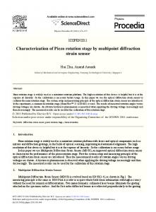
Co
m
Fig. 3. Force estimates for an object with multiple contacts
Figure 3 shows the force estimates based on three friction cones due to a three point contact of an object. Residual forces and torques at the Centre of Mass of the body are given by : 3
F = ∑ fi i =1 3
T = ∑ ri × f i i =1
where fi = the applied finger force, ri = the vector from the centre of mass to the point of contact. If the forces and torques are in a world coordinate frame then the resulting accelerations can be estimated according to Newton and Newton-Euler equations as a=
F m A
ω& = J −1 (T − ω × A J ω ) where
A
J = RJ p RT , a = linear acceleration, ω& = angular acceleration.
Jp gives the principal moments of inertia about a coordinate frame at the object centre of mass with respect to the bodies principal axes, and R is a rotation matrix to rotate this coordinate frame into the world coordinate system {A}.
Translation and Rotation of Multi-Point Contacted Virtual Objects
223
We consider in the following the case where ω is small, or that the principal inertias are not widely different and hence the second term can be neglected, thus:
ω& ≈ RJ p−1RT T Since Jp is a constant diagonal matrix, its constant inverse can be calculated outside the main control loop of the haptic interfaces. To calculate the resulting translation and rotation of the virtual object the final process must integrate the angular and linear acceleration. Given the loop time (∆t) of the control algorithm the velocity (v) and position (P) estimates can be arrived as follows v = vold + a∆t p = pold + v∆t
The angular velocity (ω) and orientation (R) estimates are
ω = ω old + ω&∆t
(1)
∆R = I + S ∆t R = Rold ∆R
where
0 S = ωz −ω y
−ω z 0
ωx
ωy −ω x 0
Since (1) is a small angle approximation of rotation it is necessary to normalise R, ie. if R is composed of three unit vectors R=[n o a] [7]: 1. Set a = a / |a|, 2. Set n perpendicular to a and o and then normalise, ie n = o × a , n = n / |n| 3. Set o perpendicular to a and n with o = a × n 3.2
Two point of contact grasps
Where a multi contact point haptic interface is used to grasp a virtual object at two points it will not be possible to rotate that object along an axis joining the two godobjects. In this case the three point contact grasp algorithm can still be used to rotate the object in the direction of the remaining orientation degrees of freedom. To achieve a rotation in the plane perpendicular to this original grasp axis, either the two finger grasp must be remade, or the object reoriented in a non-intuitive way to allow rotation in this axis. In the real world, a two finger grasp of an object does allow free rotations in all three degrees of freedom because friction between the finger pads and the object can be used to apply a torque around this axis. Two mechanisms can be
224
N. Melder, W. S. Harwin and P. M. Sharkey
used to simulate rotations about this axis due to finger pad tortional friction. Since, in real interactions, the finger pad area can be considered approximately proportional to the applied pressure, we can use the area of the friction circle as an approximate indicator of the available frictional torque available to allow these finger pad determined rotations. Solution 1 – instrumented gymbals If a Phantom with an instrumented gymbal is used for one or more of these contact points then a coordinate frame can be established on the object such that the x-axis is along the line joining the two god-objects, the y-axis is along the normal joining the centre of mass to this line, and the z-axis is perpendicular forming a right handed coordinate frame. Once the area of the friction circle (A) exceeds a critical value (Acrit) the gymbal pitch measurement can be used to rotate this coordinate frame around the x-axis and hence update the R matrix and the position vector defining the object centre of mass. Resultant torques and forces are then used to update orientations and positions around the other axes of the newly defined coordinate frame. Solution 2 - gravity induced drop A more limited solution is to use the programmed gravity to allow the object to rotate along the newly defined x-axis joining the god-objects until the centre of gravity is below the object. If the friction circle area A is greater than a critical value Acrit, then no rotation is allowed around this x-axis. If the friction circle area is less than the critical area then the resultant torque along the new x-axis is given by
A Tresultant = p × mg 1 − u u Acrit where
3.3
p = a vector from either contact point to the centre of mass, g = gravity vector, m = object’s mass, u = unit vector joining the two contact points. One point of contact grasps
Aside from pushing an object along a surface, it is possible to use a one-point of contact grasp to either balance a long object so the god-object is kept below the centre of gravity in an unstable position, such as might be used by an acrobat balancing a pole, or to lift and move an object by a handle such that the object then rotates so the centre of gravity is below the god-object.
Translation and Rotation of Multi-Point Contacted Virtual Objects
4
225
Haptic - Object - Object Interaction
The algorithms described thus far only deal with haptic interface-object interactions, ie. the manipulation of individual objects in space through a multi-point haptic system. However, a mechanism is required that allows the user to place an object on another surface (ie. object-object interaction). Using a rigid cube and an infinite floor as an example, when placing the cube on the floor, a corner will make contact first, followed by an edge and then, finally, a face. A mechanism needs to be in place to allow for these ‘rotate down’ behaviours to be realistically modelled. One approach to deal with this ‘rotate down’ behaviour is to use a force-based solution. As the first corner of the cube penetrates the floor, a force is applied to the object in the direction of the normal to the floor proportional to the depth of penetration positioned at the penetrating vertex. This force can then be added to the object’s residual force and torque to calculate the next position and orientation of the object. After a number of iterations, two corners (i.e. an edge) should be in contact but with less penetration resulting in two additional vertex forces etc. until four vertices of the cube (ie. a face) should be in contact with the floor. This method has the inherent advantage that it can be easily expanded into a full physics system to deal with non-haptic interaction as well. For example, if an object is dropped the object should bounce and rotate realistically. Another advantage of this method is that an object hierarchy does not need to be traversed to determine the overall weight of the object (ie. if an object is placed upon another object and the first object is then picked up, no extra calculations are required to determine what weight is being manipulated). Disadvantages of this method are that no surface will be rigid, a high update rate is required and losses must be included to guarantee energy conservation.
5
Implementation
The friction and residual force methods described above have been implemented and tested using up to three Phantom 1.5 haptic interfaces running rt-linux version 2.4. The drivers for the phantoms are modified from those developed by Zdenek Kabelac and Petr Konecny at the HCI-Lab, Masaryk University at Brno, Czech Republic (http://www.fi.muni.cz). The Phantoms are being updated internally at 3000Hz while the phantom positions and forces are calculated at 500Hz. All physics simulations, graphics and collision calculations are updated at 50Hz. The force based ‘rotate down’ solution has been simulated in Matlab. A problem that became apparent whilst simulating rotations is oscillations of the grasped object in a two point of contact grasp. This occurs when the object has rotated and has minimal rotational energy and is due to the low update time of the physics simulation (50Hz). Because of the low time period, the amount of rotation that would occur is enough to rotate the object past its rotational energy minima, thus causing the torque to reverse direction in the next update. This can be prevented through the use of a ‘dead band’ where the residual torque must be set to zero, ie.
226
N. Melder, W. S. Harwin and P. M. Sharkey
T, T = 0,
T > Tcrit otherwise
where T = the computed torque on the object, Tcrit = small critical value of torque.
6
Discussion
Although it might appear that the algorithm would only function when rotations are about the centre of gravity of the object this is not true. Where a combination of forces and torques are applied to the object based on interactions via the persons fingers and the synthesised physics, the object will eventually reach a static equilibrium in both position and orientation. This relies on the two integrators (for position and orientation) interacting via the body, mass and inertia, with the externally applied forces. Thus if a long 'virtual' rod is grasped with two or three fingers at one end and swung, the position of the centre of gravity of the rod will follow an arc, (as long as there is no slip at the grasp points), because both angular and linear acceleration are determined by the forces at the fingers, and discrepancies following integration will result in small forces changes at the finger friction cones that will in turn adapt the angular and linear accelerations. This playing off of the two integrators needs further investigation as a more numerically robust solution may be possible by choosing some point near the finger contact points, and calculating the resulting accelerations based on the object inertia matrix at that point. There are several perceptual issues to be determined, since the current implementation has very few visual reinforcements as to the relative position of the fingers and the object in the visual image. An avatar hand is one mechanism that is currently being investigated to aid visual reinforcement of object hand position. One of the current limitations of the friction cone method is that there is no provision for traversal of polygon boundaries. Although this is currently acceptable for simple objects, a mechanism needs to be developed so that more complex shapes can be manipulated with realistic friction. The addition of dynamic and viscous friction is also an area for further work. The solutions described for ‘rotate down’ behaviour also needs to be expanded in order to take into account situations where no vertices intersect, for example, placing a cube on a thin beam. This is a problem of collision since polygon-point collision no longer applies, being replaced with polygon-polygon collision. Once the polygonpolygon collision is detected, it is currently unclear how best to apply a suitable force to ensure realistic haptic physics.
Translation and Rotation of Multi-Point Contacted Virtual Objects
7
227
Conclusion
The friction cone algorithm provides a useful design mechanism that not only successfully models friction but also allows multifinger interactions to occur naturally. Residual forces and torques on the body due to the finger grasp as well as other interaction forces then determines the response of the body. The mechanism described is self-stabilising since resulting movement of the grasped body will affect the forces of contact at the fingers and hence the object will continually try to achieve a natural equilibrium. As a result an object can be manipulated in a virtual environment in the same manner as in the real world. A major limitation in our implementation of the system is the slow update speed of the physics and visual environment. Whereas a slow update of the physics in the visual environment (50Hz) is perceptually acceptable, the slow update of the physics in the haptic environment causes perceptual and stability problems. Efforts are currently underway to separate the haptic and visual physics and to increase the haptic rate to 1kHz.
8
Acknowledgements
The authors are pleased to acknowledge support from the EPSRC project “Haptic cues in multi-point interactions with virtual and remote objects” (GR/R10455/01) for this work.
References 1. 2. 3. 4. 5. 6. 7.
C. B. Zilles and J. K. Salisbury, A Constraint-based God-object Method for Haptic Display, Proceedings of International Conference on Intelligent Robots and Systems, 1995. S. Gottschalk, M. C. Lin and D. Manocha, OBBTree: A Hierarchical Structure for Rapid Interface Detection, Proceedings of ACM Siggraph, 1996. A. Gregory, M. Lin, S. Gottschalk and R. Taylor, H. Collide: A Framework for Fast and Accurate Collision Detection for Haptic Interactions, Proceedings of IEEE Virtual Reality Conference, 1999. P. Lischinsky, C. Canadas-de-Wit and G. Morel, Friction compensation for an industrial hydraulic robot, IEEE Control Systems Magazine, 19(1), pp 25-32, 1999. C. Richards and M.R. Cutkosky, Friction modeling and display in haptic applications involving user performance, Proceedings of the 2002 IEEE International Conference on Robotics and Automation, pp 605-611, May 2002. W. S. Harwin and N. Melder, Improved Haptic Rendering for Multi-Finger Manipulation Using Friction Cone based God-Objects, Proceedings of Eurohaptics Conference, 2002 R. P. Paul, Robot Manipulators: Mathematics, Programming and Control, MIT Press, 1981.