Translation Validation for Model-Based Code-Generators for PLCs Dirk Pollmacher Institut ftir Informatik Universitat Halle D-06099 Halle/Saale
[email protected]
Wolf Zimmermann Institut ftir Informatik Universitat Halle D-06099 Halle/Saale
[email protected]
Hans-Michael Hanisch Institut ftir Prozess- und Stoffmodellierung Universitat Halle D-06099 Halle/Saale
[email protected]
Abstract The use of model-based code-generators for construction of controller software increases the reliability of the software in two ways: First, the models often can be checked for safety conditions. Second the use of codegenerators prevents manual implementation faults. However; the reliability depends on the correctness of these code-genererators, i.e., whether they really generate code that correctly implements the model. In this paper; we show how this correctness can be checked automatically for code-generators for PLCs.
1 Introduction Programmable Logic Controllers (abbr. PLC's) are the dominating devices in today's industrial automation systems. The programming of PLC's follows the International Standard IEC 61131-3 that specifies the programming languages. In almost all applications, the control program is designed by a human programmer based on an informal, textual specification of the desired behavior of the controlled manufacturing system. Obviously, such a control program that is based on an informal specification that is neither complete nor free of contradictions will never be correct. Hence, extensive tests are needed to reduce the number of errors of the program. To overcome this unsatisfying situation, model-based methodologies have been developed in academia. Those methodologies are all based on the same idea: 1. Design a model of the controlled object 2. Design a model of the controller 3. Formalize the specifications 0-7803-9402-X/05/$20.00 © 2005 IEEE
4. Construct a model of the closed-loop behavior
5. Verify the correct behavior, if not correct, redesign the model of the controller. The result is a model of the controller that fulfills the specification when it interacts in closed loop with the controlled system. The model of the controller, however, is not the controller itself. A transformation of the controller model into a programming language for a PLC is needed to actually implement the model. Proving the correctness of this transformation is yet an open problem, even for pure logic controllers but much more for controllers that incorporate time behavior. There are basically to ways to prove this correctness: Using compiler verification techniques [12] or translation validation [16]. The latter checks whether the generated controller is correct with respect to the source and a given correctness condition in a verification phase. When translation validation is applied to a timed system, special problems occur concerning the reaction time of the system. Because reaction time may lead to faulty behavior, these problems lead to a new semantics for timed automata and adjusted correctness conditions for an implementation of a timed automaton model. The aim of this paper is to show, how the implementation of a timed automaton model can be validated using translation validation with respect to the semantics of programmable logic controllers. The paper is organized as follows: Section 2 introduces our approach for translation validation of modelbased code-generators for PLCs. Section 3 discusses our extensions of timed automata and introduces our notion of correctness. Section 4 shows how to construct correctly a timed-automaton model from the controlling program. Finally, we show in Section 5 how to use model-checkers for translation validation of timed-systems. 113
VOLUME 1
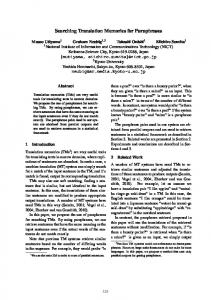
2 The Translation-Validation Approach Fig. 1 illustrates the main idea of translation validation. Ideally, the whole code-generator is not needed but only the source (the model) and the target (the PLC-program). Model -p
--
Controler Program (
i
Program Abstractior
Operational Semantics
Timed Labeled Transition System
I"abstracts
Model Checker for fo R Reiemnt
Tie Labeled aee m Transition System-
TnTimed
.
-
oe Model
yes or no with counterexamples
Figure 1. Translation Validation for CodeGenerators for PLCs Our approach satisfies all these requirements. The model is a timed labelled transition system. A timed labelled transition system is a tuple TLTS = (Q, ->, Z, I) where Q is a (possibly infinite) set of states, TQ = Q x R is the set of timed states, -*C TQ x E x TQ x R is the timed state transition relation, E is a set of symbols (called signals or events), and I C Q is an initial state. Thus, a state is a pair (q, t) which means that if state q is reached and the system remains in state q for time t. A state transition is denoted as q -t q'. Informally this means that timed state q is transformed in timed state q' by signal a and the transformation takes time t. In general, a system run can be modeled as a finite or infinite sequence of alternating timed states and state transitions, i.e.
(qo,to) *T1 (ql,ti) *T2 (q2, t2)
*T3
where qo e I. Each state qi in such a run is reached and left at a certain time. The state qo is reached at time 0 and left at time to. A state qi is reached at time t and left at time t + ti iff the preceeding state qi±+ is left at time t - ri. The system behaviour RUNS(TLTS) of TLTS is the set of all its possible system runs. Timed labelled transition systems can be typically specified by timed automata, timed Petri-Nets, timed condition-event nets etc. The idea to implement the translation validation is to check whether the operational semantics of the generated PLC-code is a refinement of the model from which it is generated. For this purpose we consider its operational semantics also as a timed labeled transition system. The translation validation is performed by two steps: First, we build a model of the generated code that is a timed labeled transition system which is an abstraction of the operational semantics of the generated program. Second, we check whether this abstract timed labeled transition system refines the timed labeled transition system defined by the model to be implemented. Symbolic model checkers can be used for this check. If it fails, a counterexample is produced, i.e., an initial segment of a run in the model
of the PLC-Code that has no counterpart in the model to be implemented. For this purpose the model to be implemented and the abstract model of the program should have a finite number of states. Theoretically, it would be sufficient to check directly whether the operational semantics of the generated PLC-code refines the model from which it is generated. However, this is practically only feasible for very small models and PLC-programs since otherwise the number of states become too large for model-checkers. Formally, a timed labeled transition system TLTS1 = (Qi, ->1, Z1, Ii)is an abstraction of a timed labeled transition system TLTS2 = (Q2, ->2,E2,12) iff there is mapping q: Qi -> Q2 such that q(Il) C '2, El C_ 2, and for every run r2 e RUNS(TLTS2) there is run ri e RUNS(TLTS1) satisfying the condition in Fig. 2 such that each state q of r, is reached at the same time as state O(q) in r2. We also say that TLTS2 is a refinement of TLTS1. The following Section discusses how timed automata describe timed labeled transition system. Then, Section 4 shows how to create a timed automata that abstracts the operational semantics of PLC-code written as Structured Text. Finally Section 5 shows how model-checkers can be used to check refinement relations for timed automata.
3 Timed Automata This section is an extension of the basic definitions regarding timed automata[l, 2]. Timed automata are based on a finite set C of clocks. An orthogonal clock condition over an arbitrary clock c C C is an inequality of the form c < q, where C C {} and q e Q. A clock constraint, denoted b, is a formula of conjunctions over orthogonal clock conditions. N(C) denotes the set of all clock constraints over a clock set C. A timed automaton is a tuple A A (L, Ilo, , C, -*,), where L is a finite set of locations', 10 C L is an initial location, E is a set of symbols, C is a finite set of clocks and ->AC L x E x DC x 1(C) x L is a set of switches where a switch l ,a:0 -A l represents a location change from I to CR
on a if X holds. Fig. 3 shows an example. Remark: For simplicity, we don't consider output except for reseting clocks. However, it is straightforward to extend timed automata and our approach for translation validation by an output alphabet. O A clock valuation v A C H-- R>0 assigns a time value to each clock. For a subset CR C C, let d: CR --> R>0 an arbitrary mapping. The clock valuation v + d is a time advance d(c) for each clock c C CR while the other clocks remains unchanged, i.e. (v + 6)(c) v(c) + d(c) if c C CR and (v + d)(c) = v(c) ifcC CR. A global time advance is a constant function d C -* R>O. We denote this simply as d C R> 0. The term V[CR o}. a timed automaton
A
(L, 10, C, ->M) is a timed labeled transition system TLTS(A) = (Q, >,Q,I) where Q = L x Yr(C), I = {(lo, V[C o wherece Z, Z,
is a new symbol, and there are two types of transitions ->:
* The elapse of time proceeds in time but remains in the location iff there is
no
)A
switch
I such that
CR
v: (l, v)
(ac)
The location switch switches from location I to switch
CR
A
such that A satisfies
(1 (1, V [CR )
C where d' C
o with Y(c)
c2
The difference to the classical timed automata according to Alur and Dill[l, 2] is that their location switch is timeless and instantenous, and that the input is timeless, i.e. d' = 0 in the definition of the location switch. Furthermore we added e to model the control behaviour if no input is given, i.e. time is passed for one cycle. It is possible to model non-instantenous and non-timeless location switches and input signals that take some time using classical timed automata at the cost of state explosion and input alphabet explosion. For more details on the necessity of extensions and notions of correctness based on timed automata see [17].
4 Timed Automata Semantics for Structured Text
(,v+a
for any (a,5) CQ. a
Cl
fines the successors of v when resetting with a reaction time 0 < d < 1.
c
T(C) -{v: v =C
there is
2
Figure 4. The possible clock valuations for two clocks c1 and c2. The hatched area de-
C C \ CR to v(c). The set of all clock valuations for a set of clocks C is denoted
to 0 and each clock
*
1