MATEC Web of Conferences 210, 03002 (2018) https://doi.org/10.1051/matecconf/201821003002 CSCC 2018
Transmitting data over the network using an OPC server Filip Niculescu1,*, Adrian Savescu1, Andrei Mitru1 1
National Research and Development Institute for Gas Turbines COMOTI, Automation Department, 220 D Iuliu Maniu Bd., Romania Abstract. The paper presents the way of transmitting the parameters of operation of a remote installation in a centralized control center of a company. The distance between the computers that collect the data and the data monitoring center is hundreds of kilometers. Data has to be transmitted through multiple physical environments and through multiple networks. This transmission channel must be very stable and secure against external threats to the company network. The monitored installation is comprised of 10 compressors each having a local control cabinet and transmitting data to monitoring computers in the control room. Centralized data in these computers are sent to the beneficiary. This transmission uses a tunneling solution provided by a company together with an OPC Server realized by using that function of the software in which the monitoring application is developed on the industrial computers in the control room of the respective installation. The results obtained in remote data transmission were very good. In conclusion, the configuration and software solutions adopted proved reliability and stability in operation.
Introduction There is a worldwide interest to use the solution to transmit the data provided by an OPC server through a tunneling application between different computers that can be in the same room or at a great distance from each other. Various companies have created software to achieve this goal as easily as possible. OPC UA technology provides an efficient and secure infrastructure for communications and has the potential to be the standard of choice to complete the vision of IP to the edge, commonly referred to as the “Internet of Things.” OPC UA is leveraging accepted international computing standards, putting automation systems on a level playing field with the general computing industry [1]. OPC UA uses common computing industry standard Web Services which are the preferred method for system communications and interaction for all networked devices. The World Wide Web Consortium (W3C, www.w3.org) defines a Web Service as "a software system designed to support interoperable machine-tomachine interaction over a network.” Matrikon OPC is releasing an OPC UA Linux toolkit to provide a proxy for OPC Classic clients to connect to OPC UA servers. GE Intelligent Platforms investment in a single integrated architecture features modular components, an Ethernet backbone and software applications all based on industry standards. As convergence continues, Connected Controls devices will enable more power at the point of control, while software applications provide local intelligence to deliver on the principles of the *
Industrial Internet and Machine-to-Machine (M2M) communications [10]. The paper presents the practical realization of the remote transmission of data from a remote compressor installation, hundreds of kilometers in the data center of the company that own the installation. The structure of the paper consists in the presentation of the installation from which the data is collected, a presentation of the software used in the data transmission, a presentation of the network configuration used in the installation, examples of the types of data transmitted, the conclusions and the references.
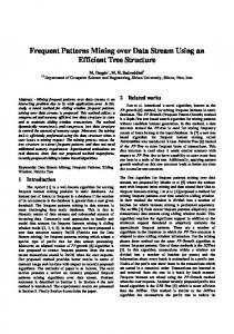
1 Presentation of the installation The air compressor plant comprises a total of 10 air compressors with a flow rate of 310,000 m3/h at a pressure of 13.5 bars. Pumped air from the compressors enters a duct where the flow of air pumped through the two ends - East and West is divided by a central tap. The pipeline has a flow meter for measuring the flow of air on East or West. The 10 compressors each with an own automation cabinet (LCP) are driven by a general station cabinet (SCP) that centralizes and coordinates their operation. Figure 1 shows a compressor, which is part of the installation. The compressor has the following features [ 1 ] : - Motor type MAB 2000 asynchronous, 1500 rpm, 6kV, 2MW, produced by Electroputere Craiova; - Flow rate: 310000 Stm3/day; - Working pressure: 13.5 bars; - 4 compression stages - Air cooling: water.
Corresponding author:
[email protected]
© The Authors, published by EDP Sciences. This is an open access article distributed under the terms of the Creative Commons Attribution License 4.0 (http://creativecommons.org/licenses/by/4.0/).
MATEC Web of Conferences 210, 03002 (2018) https://doi.org/10.1051/matecconf/201821003002 CSCC 2018
Fig.1. Compressor CCAE.
In figure 2 is showed a general view of the hall of centrifugal compressors CCAE. Fig. 3. Compressor monitors in control room
In the second phase of the project, the total flow rate QT had to be equal with the total flow measured at both ends of the pipe, according to the equation: QT = QEast +QWest
(3)
This modification was needed because the flow transducers mounted on compressor exhaust lines face more issues in operation than the flow meters mounted on pipe end.
2 Presentation of software applications used
Fig. 2. Compressor hall CCAE.
Automatic adjustment means changing the position of the valves so that the total flow QT will fit in the total setting flow QS with a deviation of 25,000 Stm3. 3
QS - 25000 Stm < QT < QS + 25000 Stm3
2.1 OPC software The OPC server is an application that behaves like an Application Programming Interface (API) or protocol converter. The OPC server connects to devices such as PLCs or to data sources such as databases or user interfaces and converts data into a standard OPC format. Compatible clients OPC applications can connect to the OPC server they use to read and write data from the corresponding device. Thus, the OPC server is similar to a driver that allows the computer to communicate with the printer. The OPC architecture is a client / server type in which the OPC server component provides an interface to the OPC objects it controls [3]. The OPC application is implemented by the Run time provider. Figure 4 shows the creation of data sources for the 10 compressors. In some documentation, instead of the term OPC Server is used the term OPC Driver. The two terms are synonyms. OPC emerged from the need for a standard communication mechanism between the many data sources or automation devices at the level production line or control room databases.
(1)
When the pumped flow falls within this range, a green lamp fixed on the station cabinet is lit and the process of changing the position of the valves ceases. Now the command for the suction valve and the flow feedback information for each compressor are transmitted via analog signals by a connecting cable between the cabinets. The overall airflow required in the application is between 1,500,000Sm3/day and 2,000,000Sm3/day. Flow regulation is obtained by closing or opening the air intake valve of each compressor. In the initial phase of the project, the total flow rate QT had to be equal with the total flow of compressors in operation, according to the equation [2]: QT = Q1 +Q2 + Q3 +...+Q10
(2)
2
MATEC Web of Conferences 210, 03002 (2018) https://doi.org/10.1051/matecconf/201821003002 CSCC 2018
3. Business Management - By installing control systems, benefits can be gained at the organization level by integrating the information gathered from the different processes into the systems management of the organization, to correlate them with the financial aspects of the production process. Providing this information to client applications in a unified manner minimizes the effort required this integration. To accomplish all of these tasks effectively, managers need to access production line data and integrate them into existing organization management systems, being able to use the available tools (SCADA packages, databases, sheets calculation, etc.) to assemble a system according to their needs. The key to success is an open and efficient communication architecture based on access to data rather than the type of data, capable of providing a common method of accessing any data source, device or database. 2.2 Tunnelling application Remote data transmission via the Internet to the beneficiary is based on a tunnelling application. For this, the Matrikon application was used. Connection reliability and security are core features of the Internet of Things (IIoT) and industry 4.0 and they are OPC UA protocol functions. Migration to this technology is the best option for transporting data today and in the future. Matrikon OPC UA Tunneller helps future-proof control infrastructure in anticipation of increased utilization of OPC UA. It takes the uncertainty out of ensuring reliable OPC Classic/OPC UA interoperability and cross-network communications. This solution is the choice to get OPC Classic-to-Classic connectivity and Classic-to-UA bridging up-and-running quickly and efficiently. The main features of the tunneling application are: 1. Enables seamless OPC data transfer through multiple mediums across geographical locations 2. Addresses problems with using OPC Classic components based on DCOM 3. Eliminates permission issues encountered across domains and workgroups 4. Provides 64-bit support both on the client side and on the server side 5. Friendly and intuitive interface with user 6. Works in Microsoft Windows environment 7. Require minimum knowledge about OPC UA Matrikon OPC UA Tunneller makes the OPC connection easy if needed between different levels of the enterprise or between different points of the globe.
Fig. 4. Compressor OPC data sources
In the information architecture of an industrial process presented in figure 5 the following levels are distinguished: 1. Production Management (Field Management) – with the widespread dissemination of "smart" automation devices, the amount of information available on the state of operation, configuration parameters, etc. has increased substantially, thus appearing the need to publish and use them by users or software applications in a unified manner. 2. Process Management - The installation of Distributed Control Systems and SCADA (Supervisory Control and Data Acquisition) for controlling and monitoring the production process facilitated centralized information gathering in electronic format, which was a manual operation before.
Fig. 6. Connection between Client and Server Fig. 5. Information architecture process control across the organization
3
MATEC Web of Conferences 210, 03002 (2018) https://doi.org/10.1051/matecconf/201821003002 CSCC 2018
3 Configuration of the data transmission
.
The 10 compressors are connected to each other via an Ethernet network. From the station cabinet switch, a connection has been created through a firewall to protect the enterprise's internal network against threats from the outside via the computer's connection to the station.
Fig. 9. Communication topology
Fig. 7. Information architecture of the compressor plant
The transmission of desired CCAE compressor parameters will be performed by configuring two OPC servers, one for each monitoring computer in the compressor station. All desired parameters in the two servers will be transferred The OPC Client Center Configuration application from the Central Hub will remotely access all the variables transferred to the OPC server, using the network between the Hub and the monitoring computers at the CCAE compressor station. Installing and configuring the OPC Tunneling software provides access for the Hub to the two OPC servers in the station. There are three licenses installed for the tunneling application, two for the computers in the station and one for the client server.
From the firewall, the connection reaches a GSM router that provides the Internet connection and, through it, a connection to the virtual network of the beneficiary. Further, the connection reaches through the various internal environments to the computer in the central HUB of the organization. Here a SCADA program takes over and displays the parameters obtained at the installation level. The data will be read from the PLCs of each compressor by the computers in the control room via the local Ethernet network. The software on these computers provides the data through an OPC server. The SCADA application operating at the control center of the company access the data through the application tunnelling. The software used to write the application running on the two computers in the control room is Proficy Machine Edition. The application panel running on the two computers is shown in fig. 8.
4 Data transmitted in the Data Center The SCADA application programmer in the beneficiary Data Center was provided with a list of variables that can be read from the PLC compressors. The list of signals transmitted in SCADA includes process values (pressures, temperatures, flows, etc.) (e.g. pump on / off, etc.) and alarms. The desired data is transmitted for each compressor.
Fig. 8. Application panel on monitoring PC [4]
To be able to run on both computers were installed licenses Runtime Machine Edition and OPC Driver. One of the computers has slightly different software because it gathers additional power parameters via a serial link. The SCADA application in the central HUB can communicate with only one computer at a time.
Fig. 10. Compressor panel on monitoring PC [4]
4
MATEC Web of Conferences 210, 03002 (2018) https://doi.org/10.1051/matecconf/201821003002 CSCC 2018 Table 3.Transmitted energy parameters
The list of transmitted data is specified as follows: - Sensor tag (s) from where the information is transmitted so that it can be identified in the P & ID diagram; - Date type (Boolean, Integer, Real, etc.) - Description of installation date; - The memory address from which the date is read; - Domain and measurement units for analogue data; - For digital (Boolean) data, the description should refer to the truth value or explicitly contain the description for both true (1) and false (0) values. Table 1.Selection of data transmitted from a compressor Name
Data Type
Wed
BOOL
Wei
BOOL
Cra2
BOOL
Tui
REAL
Pui
REAL
Ta2
REAL
CO
INT
QA
DINT
QI
DINT
PaA
DINT
PaI
DINT
Display Format
IO Address
Water vane OPEN Water vane CLOSE
On / Off
I00022
On / Off
I00023
Resistor powered Inlet oil temperature
On / Off General format General format General format General format
I00024
Description
Inlet oil pressure Air temperature before stage 2 Shutdown cause Cumulative flow today Cumulative flow yesterday Cumulative active power today Cumulative active power yesterday
R00003 R00005
2 words
R00163
2 words
R00165
2 words
R00167
8
TI204 > 85 C
10
PI110 > 15.8 bar
11
VI101 > 33 um
19
VI108 > 1,3 mm
21
TI703 > 52 C
22
PI702 < 2,0 bar
Integer
It
Integer
300012 300001 300001 300001
Name
Data Type
St_OK_C1
BOOL
St_Run_C1
BOOL
PC_est
REAL
PC_vest
REAL
TI_est
REAL
TI_vest
REAL
FI_est
REAL
FI_vest
REAL
Description Compressor C1 OK Compressor C1 Run Total pressure East Total pressure West Discharge temp. East Discharge temp. West Total flow East Total flow West
Display Format
IO Address
On / Off
I00001
On / Off
I00002
General format
R00105
General format General format General format General format General format
R00107 R00109 R00111 R00113 R00115
By configuring the two OPC servers on the two station computers it was possible to read the values of interest from each compressor in the installation and the station PLC cabinet. The installation of Matrikon Tuneller licenses allowed these values to be transferred from each station computer to the SCADA program of the organization. The results obtained by developing this solution can be multiplied in other cases where we have the same type of SCADA implemented on process computers.
Cause TI201 > 125 C
Is
IO Address
5 Conclusions
Table 2.Selection of compressor stops code
5
Integer
R00105 R00161
TI110 > 55 C
Ir
Display Format
Table 4. Selection of data transmitted from the station cabinet
R00001
2 words
1
Integer
Description Active power Phase R current Phase S current Phase T current
The station parameters from the station PLC cabinet are also copied in the OPC Server. A selection of transmitted parameters is shown in Table 4.
Note that for shutdown cause is transmitted a code that the SCADA application in the operating center interprets depending on the correspondence in a table. A selection from this table is given below.
Shutdown code
Data Type
Name Active P
References 1 . B. Li n d on , OPC UA enables Industrial Information Revolution , Ar t i cl e ( 2 0 1 2 )
The power parameters taken over by the serial link on one of the computers are also loaded into the OPC Server and from there they are read by the central SCADA application. A selection of these parameters is shown in Table 3.
2 . B. Li n d on , OPC UA Adoption by Honeywell Process Solutions , Ar t i cl e ( 2 0 1 3 ) 3 . R. Cod ob an , M an u al d e op er ar e si m en t en an t a – Com p r esor 1 5 -3 0 ( 2 0 1 5 ) .
5
MATEC Web of Conferences 210, 03002 (2018) https://doi.org/10.1051/matecconf/201821003002 CSCC 2018
4 . F. Ni cu l escu , A. Săv escu , C. Bor zea, An al og f l ow con t r ol of a n et w or k of cen t r i f u gal ai r com p r essor s, ( t o b e p u b l i sh ed ) 5 . OPC Ov er v i ew , Ver si on 1 .0 , ( 1 9 9 8 ) , d ow n l oad ed f r om t h e f ou n d at i on ' s w eb si t e OPC h t t p :/ / w w w .op cf ou n d at i on .or g 6.
F. Ni cu l escu , Com p r esoar e cen t r i f u gal e CCAE – Cam er a d e com an d a si con t r ol (2015)
7.
D. Sora, Smart mobile terminals used in the industrial applications control, Ph .D T h esi s (2011)
8.
E. Di acon escu , C. Sp ar l ean u , Communication Solution for Industrial control Applications with Multi-agents using OPC Servers, Con f er en ce Pap er , ICAT E ( 2 0 1 2 )
9.
S.Jaszczak , Multiplatform OPC client managing PLC controllers in the direct digital level, Ar t i cl e (2014)
10. *** GE Invests in the Future with Controls Convergence Strategy, (2014)
6