FIELD REPORT
TRESSA: Teamed Robots for Exploration and Science on Steep Areas • • • • • • • • • • • • • • • • •
• • • • • • • • • • • • • •
Terry Huntsberger, Ashley Stroupe, Hrand Aghazarian, Mike Garrett, Paulo Younse, and Mark Powell
Mobility & Robotic Systems Section Jet Propulsion Laboratory Pasadena, California 91109 e-mail:
[email protected] e-mail:
[email protected] e-mail:
[email protected] e-mail:
[email protected] e-mail:
[email protected] e-mail:
[email protected]
Received 15 November 2006; accepted 4 August 2007
Long-duration robotic missions on lunar and planetary surfaces 共for example, the Mars Exploration Rovers have operated continuously on the Martian surface for close to 3 years兲 provide the opportunity to acquire scientifically interesting information from a diverse set of surface and subsurface sites and to explore multiple sites in greater detail. Exploring a wide range of terrain types, including plains, cliffs, sand dunes, and lava tubes, requires the development of robotic systems with mobility enhanced beyond that which is currently fielded. These systems include single as well as teams of robots. TRESSA 共Teamed Robots for Exploration and Science on Steep Areas兲 is a closely coupled three-robot team developed at the Jet Propulsion Laboratory 共JPL兲 that previously demonstrated the ability to drive on soil-covered slopes up to 70 deg. In this paper, we present results from field demonstrations of the TRESSA system in even more challenging terrain: rough rocky slopes of up to 85 deg. In addition, the integration of a robotic arm and instrument suite has allowed TRESSA to demonstrate semi-autonomous science investigation of the cliffs and science sample collection. TRESSA successfully traversed cliffs and collected samples at three Mars analog sites in Svalbard, Norway as part of a recent geological and astrobiological field investigation called AMASE: Arctic Mars Analog Svalbard Expedition under the NASA ASTEP 共Astrobiology Science and Technology for Exploring Planets兲 program. © 2007 Wiley Periodicals, Inc.
Journal of Field Robotics 24(11), 1015–1031 (2007) © 2007 Wiley Periodicals, Inc. Published online in Wiley InterScience (www.interscience.wiley.com). • DOI: 10.1002/rob.20219
1016
1.
•
Journal of Field Robotics—2007
INTRODUCTION
The TRESSA 共Teamed Robots for Exploration and Science on Steep Areas兲 system, previously cited in the literature as Cliffbot 共Pirjanian et al., 2002; Mumm, Farritor, Huntsberger & Schenker, 2003; Schenker et al., 2003b; Mumm, Farritor, Pirjanian, Leger & Schenker, 2004兲, is designed to allow access to steep slopes that are not feasible for traditional wheeled rovers. Such steep slopes and cliffs are of significant scientific and geological interest. Vertical faces provide a large range of geological history, as evidenced by Burns Cliff in Endurance Crater and Cape Verde at Victoria Crater on Mars. A deep drilling mission is logistically expensive due to the size and mass of a deep drilling rig, and surface exploration only gives a single timeslice. An autonomous or semi-autonomous robotic ability to access steeply sloped areas is critical for lunar and planetary surfaces, where human exploration may be decades away. Additionally, there may be planetary or terrestrial cliff sites of scientific interest that are too remote or dangerous for humans to safely explore. Traditional wheeled robotic vehicles are unable to traverse cliff faces; vehicles such as Mars Exploration Rovers 共MER兲 are not statically stable beyond about 45 deg and cannot climb slopes greater than about 30 deg. There are two objectives that must be addressed for realistic mission scenarios: safe mobility and sample acquisition on the cliff face. 1.1.
ASTEP Field Campaigns
The NASA ASTEP 共Astrobiology Science and Technology for Exploring Planets兲 program has funded a number of field expeditions since 2003. The goal of the program is to test instruments and systems for detection of life and/or evidence of life on planetary surface and subsurface environments 共e.g., Mars and Europa兲 through expeditions to terrestrial analog
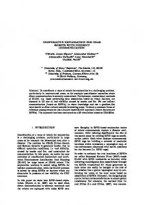
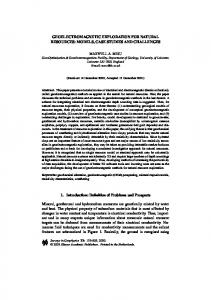
field sites. Examples of these expeditions include the Atacama Desert Trek for rover-based instrument use 共Wettergreen et al., 2005兲, MARTE 共Mars Analog Research and Technology Experiment兲 for robotic core drilling at Rio Tinto 共Hogan, 2005兲, ESP 共Environmental Sample Processor兲 for sensing in deep-sea and hydrothermal vent fluids 共Roman et al., 2005兲, and DEPTHX 共Deep Phreatic Thermal Explorer兲 for robotic exploration of underwater caves 共Fairfield, Kantor, & Wettergreen, 2007兲. The primary emphasis on these field expeditions has been the use of robotics to satisfy science goals in extreme environments. In addition, a “flightlike” mission process for ground-in-the-loop interaction is a desired component. AMASE 共Arctic Mars Analog Svalbard Expedition兲 explored a number of sites of scientific interest on the island of Svalbard, Norway in August of 2006 under NASA ASTEP funding. Svalbard represents a unique collection of several Mars relevant environments, including relic carbonates, cryptoendolithic communities, carbonate globules 共similar to Mars meteorite ALH84001兲, micro-fossiliferous beds, cryogenically precipitated carbonates, glaciers, concretion sites, sulfate rich evaporitic sediments, and Devonian sandstones exhibiting weathering patterns similar to those seen on Mars 共Steele, Schweizer, Amundsen, & Wainwright, 2004兲. The main research sites visited on last year’s expedition were the Sverrefjell Volcanic Complex 共the dark feature at right in Figure 1兲, the Devonian sandstone beds at Bockfjorden 共at left in Figure 1兲, and the evaporitic Ebbadalen Formation in Billefjorden 共Figure 2兲. Access to and sample acquisition at these sites are beyond the capabilities of current rover systems, and the closely coupled robotic team of TRESSA offers an alternative approach. The field campaign objectives for AMASE were to
Figure 1. Combined image of the Bockfjorden site showing the Devonian sand stone beds to the left and the Sverrefjell volcanic complex to the right. Journal of Field Robotics DOI 10.1002/rob
Huntsberger et al.: TRESSA • 1017
Figure 2. Ebbadalen Formation evaporite with sulfate bearing clastic sediments similar to those studied by the Mars Exploration Rover Opportunity.
• determine maximal TRESSA operations pa-
• •
rameters, including terrain roughness, slope, communications, slip imaging, and sample acquisition, determine best sample handling protocols for use in field instruments, and perform a remote campaign of rover and instruments to test science goals in the field.
These objectives were tested within a flightlike command environment where a ground-in-the-loop cycle modeled after that of MER was followed. The single cycle per day MER operations environment was emulated using an accelerated planning and sequencing schedule 共four to ten cycles per emulated day兲 in order to maximize the use of field time.
1.2.
Related Steep Terrain Access Work
Previous work in robot rappelling/tethered climbing was done for the DANTE-II legged robot 共Apostolopolous & Bares, 1995; Krishna, Bares, & Mutschler, 1997; Bares & Wettergreen, 1999兲, which explored a volcanic crater wall. DANTE-II laid the groundwork for access to steep, rough terrain using behavior-based control and was one of the first robotic systems to attempt science investigations in such environments. DANTE-II had a single tether, which, due to stability concerns, limited it to almost Journal of Field Robotics DOI 10.1002/rob
purely vertical motion. A more recent example of a single tethered walking robot for steep terrain access is the ATHLETE rover being developed at the Jet Propulsion Laboratory 共JPL兲 共Hauser, Bretl, Latombe, & Wilcox, 2006兲. ATHLETE uses a motion planner to compute foot placements in rough terrain areas. Both DANTE II and ATHLETE are very large vehicles that are more suited for lunar rather than Mars exploration. Fine positioning for science targeting on cliff faces, however, requires the ability to move up and down the cliff as well as laterally across the face. Multiple tethers such as used for a legged system designed to consolidate rock faces 共Bruzzone, Molfino, Acaccia, Michelini, & Razzoli, 2000兲 provides the extra degrees of mobility and stability. TRESSA departs from the systems that use relatively low-level modules in order to build systems with enhanced capabilities 共i.e., Rus, 1998; Yim, 2000兲 in that the control system used for the components of TRESSA is that of a full-fledged autonomous vehicle. All of the previous developments in rover mobility and autonomy for advanced operations from the FIDO 共Field Integrated Design and Operations兲 rover 共Schenker et al., 2003a; Huntsberger, Cheng, Stroup, & Aghazarian, 2005兲 can be brought to bear on the multiple robot control problem. Another alternative method for cliff access uses a limbed mobility system that free-climbs directly on the cliff face much like a human climber. Examples of this type of system include the LEMUR IIb rover being developed at JPL 共Kennedy et al., 2006; Hauser, Bretl, & Latombe, 2005兲 that can free-climb or use ultrasonic drills on its limbs to drill into the cliff face for support, and the StickyBot being developed at Stanford 共Asbeck, Kim, Cutkosky, Provancher, & Lanzetta, 2006兲 that uses dry adhesive spines on its feet to adhere to the climbing surface. The StickyBot would probably have difficulty climbing highly irregular surfaces with loose material. Both of the limbed systems would have relatively limited speed compared to wheeled rovers for traversing between sites and would probably be used in a marsupial arrangement to address this point. TRESSA in its final form will be a modular robotic system that travels as a unit and autonomously reconfigures itself as dictated by terrain. An artist’s concept is shown in Figure 3, where from left to right the TRESSA system travels to the top of a cliff face, the three rovers distribute, leaving a tethered system of two Anchorbots, which anchor themselves
1018
•
Journal of Field Robotics—2007
Figure 3. Modular robotic TRESSA system concept. From left to right: the three-rover system travels as a unit to the top of the cliff, disconnects, and plays out the tethers, and the Cliffbot traverses onto the cliff face.
at the top, and a Cliffbot, and then the Cliffbot traverses onto the cliff face using the tethers for stability. The two Anchorbots adaptively control their tether tension and velocity to maintain Cliffbot stability as it traverses over the cliff face. The Cliffbot drives on the cliff face more or less like a rover would drive on level terrain. At the end of the scientific investigation, the three robots then reconfigure for driving prior to moving to the next site. Due to cost and timing constraints, the current configuration is built with a fully functional Cliffbot and two Anchorbots that move linearly along a rail, but are not fully mobile. The next section gives the high level details of the TRESSA system. A full discussion of the technical details of TRESSA have been reported in numerous publications 共Pirjanian et al., 2002; Mumm et al., 2003, 2004; Huntsberger et al., 2003a, 2003b; Schenker et al., 2003a, 2003b; Huntsberger et al., 2004, 2005; Paulsen, Farritor, Huntsberger, & Aghazarian, 2005兲, and only details pertinent to the field expedition will be described here. This is followed by a discussion of the cliff driving and science acquisition algorithms. TRESSA operations are described next, followed by the presentation of the field expedition results. A discussion of lessons learned and description of future work finish the paper.
2.
THE TRESSA SYSTEM
In order to maintain a flightlike approach for possible future missions, TRESSA derives its robot control, mobility, and science acquisition algorithms and processes from MER, implemented in the FIDO software architecture 共Schenker et al., 2001兲. The FIDO software architecture 共now known as the Robust Real-
Time Reconfigurable Robotics Software Architecture or R4SA兲 was developed, in part, for MER prototype field trials 共Tunstel et al., 2002a, 2002b兲 and has been used on more than ten robotic platforms at JPL and on unmanned boats for the US Navy. Coordination of the three rovers is done under the CAMPOUT 共Control Architecture for Multi-robot Planetary Outposts兲 behavior-based multi-robot system 共Huntsberger et al., 2003a兲 running on top of the R4SA. In addition, several of the autonomy algorithms developed for MER have been incorporated into the R4SA, including new versions of terrain analysis, and visual odometry for tracking rover slippage during motion 共Huntsberger et al., 2003b兲. The Cliffbot is commanded using basic arcs and turns, or using go-towaypoint commands. Basic science operations make use of stereo vision for target tracking and positioning. Instrument placement trajectories are computed using inverse kinematics. Using a similar model to MER science operations, instruments are placed using contact switches to accurately find target surfaces. The Cliffbot uses the front hazard cameras that are then downlinked and used for verification to record instrument placement and sample acquisition operations, as is also done by MER. The MER model for command and science interaction will be used for upcoming planetary surface rover missions over the next decade and is familiar to the science team. The ASTEP program is designed to develop missionlike systems and control methods and fully autonomous exploration of steep terrain like cliff faces without humans in-the-loop is many decades in the future. 2.1.
Hardware
TRESSA consists of three autonomous robots, working cooperatively. The Cliffbot is a four-wheeled Journal of Field Robotics DOI 10.1002/rob
Huntsberger et al.: TRESSA • 1019
Figure 4. Tether attachment assembly mounted on Cliffbot with the 2-DOF resolvers for sensing tether pitch and yaw and a load cell for tether tension. Figure 5. TRESSA system prototype consisting of a mobile Cliffbot tethered to two fixed Anchorbots.
light weight rover 共⬃8 kg兲 that is about the size of a small child’s wagon. It has independent four wheel driving and independent four wheel steering. A tether attachment assembly 共shown in Figure 4兲 is mounted on the back of the Cliffbot coupled to the tether with a 2-DOF 共degrees-of-freedom兲 resolver for sensing of tether pitch and yaw and a load cell for tether tension. This assembly was designed and validated for rover stability on cliff faces using the Darwin2K genetic algorithm design tool 共Leger, 2000兲. The Cliffbot has a PC104+ stack running R4SA and CAMPOUT. It has a 4-DOF arm for science instruments, and a single stereo pair of hazard cameras 共Hazcams兲 for navigation. The rover arm is equipped with a scoop and a color microscopic imager 共CMI兲 as its default instrument set mounted on a revolving turret that can accommodate up to a total of four instruments at the end of the arm. The CMI is a fixed focus instrument and has a contact ring that triggers on a surface at the optimal focal distance. The contact ring is necessary because there is enough uncertainty in the range maps 共typically ⬃1 cm兲 that are derived from the front stereo hazard cameras to preclude a safe placement entirely based on those measurements. MER uses the same process for deployment of its microscopic imager. The scoop is mounted on a six-axis force-torque sensor for monitoring contact forces during sample acquisition. The full system is shown in Figure 5 without the instrument arm. Journal of Field Robotics DOI 10.1002/rob
Due to timing and cost constraints, the mobile Anchorbots illustrated at the top of the cliff in Figure 3 have been emulated using two independent computer-controlled winches. Each Anchorbot winch is also controlled by a PC104+ stack running R4SA and CAMPOUT as a tightly coupled cooperative team with the Cliffbot. The winch Anchorbots are mounted on an actuated rail with a single degree of freedom for movement toward and away from the cliff face to assist in cliff edge navigation. The emulated Anchorbot mechanism is shown in Figure 6.
2.2.
Cliff Surface Driving
Adapting mobility to slopes requires addressing issues of stability under gravity, adapting hazard models to incorporate the slope of the terrain, and accounting for the effects of steep slopes 共such as slipping兲 on path planning. Current work has primarily focused on stability issues for operating on the slopes. A better understanding of slope driving allows further characterization of hazards and safe areas for the purposes of improving hazard detection and avoidance in path planning. At present, terrain modeling makes no considerations for steep slope operations and the safety of the terrain is determined by operators.
1020
•
Journal of Field Robotics—2007
Once stable, the Anchorbots send a message to the Cliffbot that signals it to begin driving. Once the Cliffbot reaches the goal, it stops driving and sends a message to the Anchorbots. Upon receiving this message, the Anchorbots ensure that the tension is stable in the tethers and then complete their motion. If a desired goal is unreachable, or if any robot experiences a mechanical failure, a different message is sent which causes each robot to enter a clean-up and stop mode.
Figure 6. Anchorbot emulation with a computercontrolled winch mechanism able to travel along a rail.
Cliff driving for TRESSA is implemented as a cooperative multi-robot behavior-based system, illustrated in Figure 7. In this system, a command is sent indicating a goal position on the cliff for the Cliffbot. If the Cliffbot determines that the goal is reachable and safe, it sends a signal to the Anchorbots. This signal triggers the Anchorbots to initialize tension control in the tethers to ensure gravitational stability on the slope 共see Section 2.2.1 for details兲.
Figure 7. High-level view of cliff driving under TRESSA. The Anchorbots and Cliffbot exchange synchronization messages 共shown as dotted arrows兲 for the start and ending of a traverse. Tether tension control is primarily achieved through varying the tether velocity based on tension feedback on the tether attachment assembly.
2.2.1. Stability The ultimate goal of the TRESSA system is to deploy a science rover on steep slopes 共up to 85+ deg兲. Operating on steep slopes in a realistic planetary surface mission context introduces new issues of stability that will by necessity limit the size and mass of the robot. Several approaches to operating on slopes are currently under investigation as described in Section 1.2, including approaches modeled on free climbing and rappelling. Tether-aided climbing simplifies the stability problem: tethers anchored at the top of the slope essentially reduce the threedimensional problem to a two-dimensional one. The tethers directly counter the gravitational forces and prevent the robot from falling even if it enters into a configuration that would, alone, be unstable. Tethers can also assist in climbing up-slope by pulling to overcome initial friction or excessive slip. This allows the climbing robot to be potentially larger and heavier than a free-climbing robot, which improves the robot’s ability to carry power and science instruments. An initial PID controller was developed at JPL jointly with University of Nebraska, Lincoln 共Mumm et al., 2003, 2004; Paulsen et al., 2005兲. This controller was successful in many laboratory and preliminary field tests. It consisted of two components: a component to counter gravity and a component to assist in obtaining a desired climbing robot velocity. This controller, while providing both desired components of force, ultimately was too computationally intensive to run in real-time once additional required communications for synchronization were incorporated into the system. As a result, only the gravitational component of the controller is currently used. The desired tension for the gravity controller component is provided in 共1兲 关details of the velocity controller component are in 共Paulsen et al., 2005兲兴: Journal of Field Robotics DOI 10.1002/rob
Huntsberger et al.: TRESSA • 1021
Figure 8. System parameters and components. Left: ␣ and  define the slope of the cliff. Right: Tether yaw angles from the rover to the Anchorbots define desired forces for each Anchorbot, as well as define which directions are stable for the rover.
Ti =
m sin 共j兲关g sin 共␣i − i兲兴 sin 共i兲 cos 共j兲 + cos 共i兲 sin 共j兲
共1兲
where Ti is desired tension for Anchorbot i, m is the rover mass, and i, j are yaw angles to tethers i and j, respectively. The angles used in the controller are shown in Figure 8. The gravitational component is determined by first estimating the slope using the difference between the vertical angles of the tether to the Anchorbot winches 共␣兲 and to the Cliffbot tension sensors 共兲. This slope and the mass of the rover determine the required gravitational force, which is factored into components for each tether based on the lateral angles to each tether 共兲. The original controller used a fuzzy rule set at each time step to determine a stable rover heading 共Pirjanian et al., 2002; Mumm et al., 2003; Schenker et al., 2003b; Mumm et al., 2004兲. Four different behaviors 共maintain tension, match velocity, stability, and haul兲 were fused using the fuzzy rule set. This additional complexity contributed to the real-time issues described above and was therefore simplified. Instead, rover paths are limited to linear paths, each segment implemented by a separate cliff driving command. Prior to executing any drive, the path to the goal is determined. Paths that take the rover outside the range of support vectors provided by the Anchorbots are unstable 共see Figure 9 for examples兲. If rover stability over the entire path is determined to be safe, the rover sends a ready message to the Anchorbots. Stability in this case refers to the supJournal of Field Robotics DOI 10.1002/rob
Figure 9. Illustration of example rover instability areas. Left: Both tether angles are nearly vertical, limiting the Anchorbot ability to support lateral motion. Right: Only the right tether is nearly vertical, limiting the right Anchorbot from supporting any lateral motion.
port given by each tether to the Cliffbot. If the Cliffbot is directly underneath one of the winches, lateral stability will be compromised. If the path is not stable, the rover looks for a stable path near the desired heading. The heading to the goal is checked to find if there is a stable path within 5 deg of the desired and if so, this heading is selected and the ready signal is sent. Five degrees was chosen based on a 5 cm localization offset over a 50 cm path. In the event that a safe stable path is not found, an abort message is sent; the system does not execute any motion and returns a failure.
2.2.2.
Navigation
The Cliffbot is equipped with stereo vision and the same terrain modeling 共JPL stereo兲, terrain analysis, local path planning, and slip estimation 共visual odometry兲 software algorithms as MER. Technology versions of these tools have been integrated into R4SA. An example of a front Hazcam 共hazard camera兲 image is shown in Figure 10. Typically, steep slopes are considered as hazardous 共typical unsafe slopes for MER are those greater than 20 deg兲. For TRESSA, an upper limit of 90 deg is a known hazard 共tethers cannot translate forces past overhangs or support a rover upside-down兲, but the interaction of slope with terrain irregularities is not yet well understood. In the recent field expedition, operators
1022
•
Journal of Field Robotics—2007
be detected after the system has started. A robot drop out 共such as due to battery failure兲 is currently in development. 2.3.
Figure 10. A Cliffbot left fron Hazcam camera image under bright illumination conditions. Potential arm and drive target surfaces are visible.
determined safe paths using the Hazcam images and commanded the rover to take small 10 to 50 cm steps, as is also done by MER rover drivers when making a final approach to a science target. If a path is visually determined to be safe for a longer traverse with the Cliffbot, that waypoint on the cliff face is sent to the rover.
2.2.3.
Fault Detection and Handling
The earlier Cliffbot implementation relied on human assistance to coordinate the start of motion and to detect failures 共Pirjanian et al., 2002; Mumm et al., 2003; Schenker et al., 2003b; Mumm et al., 2004兲. Only tension and angle information were provided from the Cliffbot to the Anchorbots at each time step. This is, however, inadequate for operations in the desired domain, where human intervention is impractical. In the current implementation, message passing between the Anchorbots and the Cliffbot is used to synchronize motion and to inform teammates of known failures. A publish/subscribe message passing system was implemented to coordinate the state changes of the system. If at any stage the expected messages/ responses were not received within the expected time, a system failure is initiated and the robots stop. These synchronization and information messages are illustrated as dotted lines in Figure 7. At present, only physical failures 共motor stalls for example兲 can
Science and Sample Acquisition on Cliffs
The ultimate goal, scientifically, for TRESSA is to safely place a variety of science instruments on specified targets on steep slopes, and to collect small samples 共soil, pebbles, rock scrapings兲 to be transferred to either on-board-science instruments or science instruments fixed at the cliff-top. Since the Cliffbot is on a fairly steep incline, moments induced by the deployment of the instrument arm, placement on a science target, or acquisition of a sample could introduce slip down the cliff face. The closely coupled teaming of the Anchorbots and the Cliffbot through the tethers mitigates slip through the tether tension monitoring and Anchorbots response during the various arm movements. The current tool suite on the end of the Cliffbot instrument arm is shown in Figure 11 and includes a sample acquisition scoop, a color microscopic imager 共CMI兲, and Raman and reflectance spectrometers that are not currently mounted rigidly on the instrument turret. Most work has thus far focused on instrument placement and acquisition of soil samples. The intent is to perform instrument placement as done with MER, using stereo terrain models that have been calibrated relative to the arm to eliminate position errors due to model inaccuracies. The issues of
Figure 11. The current TRESSA Science Instrument suite: scoop for sample acquisition, color microscopic imager 共CMI兲, Raman spectrometer, and reflectance spectrometer. Journal of Field Robotics DOI 10.1002/rob
Huntsberger et al.: TRESSA • 1023
sample handling on standard surfaces are still an ongoing research problem, and the field work reported here is primarily focusing on the additional issues raised by performing science on slopes. As with the rover stability, the stability of the sample under gravity must be considered during the sample acquisition process: the orientation of the sampling mechanism relative to the surface and relative to gravity during acquisition must be considered to prevent spillage. Hazcam imaging and stereo modeling are currently used to provide 3D target positions. The primary method for sample acquisition on slopes uses a small scoop. In order to successfully acquire samples in the scoop, the approach to sampling on cliffs relies on adjusting the tool approach angle away from the surface normal to keep the scoop more horizontal. Given an estimate of the slope steepness and the surface normal of the sampling site, the appropriate scoop angle for sampling is determined onboard, and the sample integrity is validated by viewing Hazcam images prior to closing the scoop. This is similar to the approach used on MER, where Hazcam images are used to verify instrument placement.
2.4.1.
Maestro is the next generation of SAP 共Science Activity Planner兲 interface 共Jis et al., 2005兲 used for building sequences and visualizing data for MER. The application user interface provides two sets of tools for operations: image browsing and command generation. The image browsing views 共shown in Figure 12兲 let the operator see the time-ordered history of images returned from the rover cameras. 3D information derived from stereo imagery is used for science target and navigation waypoint selection. The ground operator generates a sequence of commands with Maestro to be executed by the rover. A command dictionary tree view in the lower left of the interface lists all commands that the onboard command dispatcher recognizes and the sequence being built is displayed in the right panel of the interface. This portion of the interface is similar in operation to the RSVP 共Rover Sequencing and Visualization Program兲 that is used by the rover drivers for planning on MER.
3. 3.1.
2.4.
User Interfaces
The closely coupled three-robot team is commanded via either of two interfaces. The first is a menu-based sequencing tool built into R4SA that is used for development. The second, used for field operations, is the combination of two applications: Orchestrator and Maestro. TRESSA Orchestrator is a data processing pipeline application that receives telemetry from the rover over a wireless network connection and processes the raw data into derived products that are useful for planning new operations. TRESSA Maestro is a graphical operations user interface that lets the operator browse and examine the telemetry and plan new command sequences for TRESSA based on the contextual knowledge of vehicle state and knowledge of the terrain. Orchestrator and Maestro are built upon software and operations support experience from many other rover tasks conducted by the Jet Propulsion Laboratory, recently including MER mission operations support 共Jis, Powell, Fox, Rabe, & Shu, 2005兲 and MER-FIDO Athena field trial support 共Tunstel et al., 2002a兲. Journal of Field Robotics DOI 10.1002/rob
Maestro
FIELD EXPEDITION IN SVALBARD, NORWAY Field Operations
In August of 2006, TRESSA was deployed at three cliff sites 共Ebbadalen, Sverrefjellet, and Red Beds兲 in Svalbard, Norway as part of a NASA funded ASTEP effort called AMASE. These cliff sites are of interest to planetary geologists and astrobiologists as Mars analogs, and the TRESSA team was part of the larger AMASE science team being led by Dr. Andrew Steele of the Carnegie Institute of Washington 共CIW兲. In order to be relevant for planetary science applications, the science goals were set by members of the AMASE scientific team. Transportation between the cliff sites was on the icebreaker Lance, with the TRESSA system then carried to the site 共usually within 2 km兲 and deployed. A model of operations was developed based on those currently in use for MER. A day in MER starts off with a Science Operations Working Group 共SOWG兲 meeting where the science goals for the day are planned. The operations team then plans the sequence of activities that the rover will perform during that day 共Leger, Deen, & Bonitz, 2005兲, including imaging, motion, and instrument arm operations. The sequence is uploaded to the rover and executes.
1024
•
Journal of Field Robotics—2007
Figure 12. The TRESSA Maestro image browser showing a confirmation front hazcam image 共left兲, a terrain view used for instrument placement 共top right兲, and a color microscopic imager image 共bottom right兲.
Engineering and science data are sent back to Earth and used to repeat the cycle the next day. Equivalent operations for four to ten sols 共Martian day兲 were emulated during each day at a site for the field trial, since constraints on downlink times and rover uptime were not an issue as they are on MER. This is the same process that was followed in the FIDO/ MER field trials, where two sols were emulated during each day 共Tunstel et al., 2002a, 2002b兲. Orchestrator processed all of the telemetery products producing stereo height maps for instrument placement and navigation, and Maestro was used to browse and analyze the image data. A new science operation, not used on MER because there is no sample acquisition tool on the MER rovers, was developed for this season—sample acquisition via digging. A detailed description of field results and activities at the individual sites follows. Prior to the field expedition to Svalbard, Norway, many hours of cliff driving in the lab and the Arroyo Seco next to JPL were conducted to validate system performance and operations. Our lab setup 共shown in the left image of Figure 13兲 consists of a 2.5 m long slope tilted at 50 deg. The test driving included vertical, horizontal, and diagonal drives, as
well as continuous sequences of the above. The current controller successfully detected all unreachable goals and reached all reachable goals without entering any unstable states. The simplified controller does not compromise Cliffbot safety or performance. A number of randomly induced errors including loss of communication, tether tension control failure, and winch battery failure were successfully handled through the synchronization communication primitive, with the Cliffbot maintaining a stable safe state. 3.2.
Field Expedition Results
Over a 1 week period in August 2006, TRESSA was deployed at three steep slope or cliff sites in Svalbard, Norway that are of interest to planetary geologists and astrobiologists as Mars analogs. The sites also were used to evaluate how well the TRESSA system met the objectives given in Section 1.1. The SOWG meeting was held onboard the icebreaker each morning, followed by a check for polar bears at the current site, transport of the TRESSA system to the site, deployment on the cliff face, and then execution of the sequence of operations to meet the science goals for the day. The equivalent of multiple Journal of Field Robotics DOI 10.1002/rob
Huntsberger et al.: TRESSA • 1025
Figure 13. Testbed setups at JPL. Left: Indoor carpet-covered laboratory ramp 2.5 m tall and 50 deg; Right: Granite cliff face in the Arroyo Seco next to JPL, which is 4 m tall and ranges in slope from 66 to 84 deg.
days of flight operations were done at each site, with the science team and TRESSA drivers evaluating the results from the Cliffbot in the field and planning the next sequence. The Anchorbots were secured to the top of the cliff using bags of rocks that were tied to the base platform. All of the sequences were planned in relative isolation by the TRESSA drivers based on the telemetry feed from the Hazcams and the science instruments. The Cliffbot scoop was sterilized using a seven step process that will be reported on in an upcoming special issue of the Astrobiology journal. Samples that were acquired by the Cliffbot scoop were placed in sterile containers at the bottom of each of the cliffs. This limited operations to singlesample investigations between resterilization. During the August 2006 TRESSA field expedition to Svalbard, Norway, the Cliffbot captured 250 Front Hazcam stereo image pairs and 18 CMI images. The
results are summarized here in Table I, and the results of individual deployments are discussed in the following sections. The fault handling capability of TRESSA safely addressed the loss of battery voltage at the Ebbadalen and Arroyo sites, missed the loss of tension control by one of the Anchorbots at Ebbadalen 共Cliffbot remained safe due to the other tether兲, and missed a tether lockup condition at the Red Beds site 共leading to what would be considered a mission-ending catastrophic failure兲. This failure mode was not anticipated and is now being addressed through a system heartbeat in the communication primitives. 3.2.1. Ebbadalen The selected site at Ebbadalen shown in Figure 14 was a 70– 85 deg rough, rocky cliff face, approxi-
Table I. Summary of results. Site
Lab cliff
Lab floor
Ebbadalen
Sverrefellet
Red Beds
Arroyo
Slope 共deg兲 Surface Meters driven Drive commands Faults detected Samples collected CMI images Spectra
50 Wood 51.5 113 12 ... ... ...
0 Sand ... ... ... 5 ... ...
70–85 Rock 2.75 17 1 of 2 1 1 ...
50–60 Rock 1.5 23 0 of 0 2 1 2
60–90 Rock 13 47 0 of 1 1 4 ...
66–84 Rock 3 14 1 of 1 0 2 ...
Journal of Field Robotics DOI 10.1002/rob
1026
•
Journal of Field Robotics—2007
mately 4.5 m in vertical height. The goal at this site was primarily to prove the ability of the system to function in the environment, place science instruments, acquire Hazcam and microscopic images of the cross-bedding in the rock face, and collect soil samples. Human access was possible from the top and bottom. With no flat area at the top of the cliff, the rover was 共by necessity兲 initially positioned on the cliff face. The rover descended vertically approximately 3 m from the top of the cliff 共in 0.1 to 0.5 m steps兲 to a location where soil had collected in a locally flatter area. There were small commanded Cliffbot positioning changes to place the desired soil area within the reach of the arm, including small adjustments upward and diagonally on the cliff face. At this location, the Cliffbot successfully took a series of microscopic images and, with direct human intervention in the visual guidance of the scoop due to the sample sitting under an overhang, collected a soil sample. A Cliffbot Hazcam image of CMI placement is shown in Figure 15 where the cross-bedding in the rock face is evident to the right of the arm.
Figure 15. Rover image 共left eye兲 of CMI placement at Ebbadalen.
3.2.2. Sverrefjellet The selected site at Sverrefjellet shown in Figure 16 was a 50– 60 deg slope consisting of soil and rock; it was approximately 1.5 m in height and could be accessed by humans from the top and bottom. A large plateau existed at the top of the slope, allowing the
rover to autonomously drive over the edge from the top. The goal at this site was to perform multi-modal scientific analysis and sample acquisition on targets at vertical levels along the cliff face. The rover started on the flat surface above the cliff, drove over the edge with the Anchorbots monitoring the tension on the tethers, and then descended approximately half-way down the slope, stopping at two locations for science. The traverse included a short 20 cm drive up the slope and several downward diagonal 20 cm drives to reposition at each target. At each site, CMI images were taken
Figure 14. Left: The Ebbadalen deployment site. Right: Cliffbot rover closeup on Ebbadalen cliff face.
Figure 16. The Cliffbot rover deploying science instruments at Sverefellet. Journal of Field Robotics DOI 10.1002/rob
Huntsberger et al.: TRESSA • 1027
Figure 18. Sandstone cliffs at Bockfjorden 共human climber on left side of picture provides scale兲. The approximate Cliffbot path is shown with the white line.
Figure 17. Cliffbot scoop collecting a soil sample at Sverefellet.
and a sample was collected. The wheels were cocked perpendicular to the slope for added stability during sample acquisition 共as seen in Figure 16兲. At the first site, both spectrometers were placed on the same target for compositional analysis. The scoop was sterilized between samples 共by hand兲 to prevent crosscontamination. As a control, the same approximate locations were sampled by a human prior to the TRESSA deployment. The results of the comparison analysis will appear in an upcoming special issue of the Astrobiology journal. Figure 17 shows a sample collection operation. 3.2.3. Red Beds The Red Beds site shown in Figure 18 is a rough, rocky cliff approximately 20 m in height with slopes from 60 to 90 deg. A small flat area at the top provided an anchor point for the system. The goal at this site was to do a long traverse, as well as to take images and collect samples. The face is very unstable with loose rock throughout. This site compares directly with the Burns Cliff and Cape Verde sites on Mars. Journal of Field Robotics DOI 10.1002/rob
The rover successfully drove over the edge from the flat area at the top and then drove approximately two-thirds of the way down the cliff 共about 15 m兲. A side view of Cliffbot taken about half-way through the traverse is shown in the left side of Figure 19. At each step of the traverse, the rover took images with the stereo Hazcam images to document terrain, target placements, and handoff operations. Although part of the cliff face under the Cliffbot’s left front wheel was dislodged during the descent, the tethers maintained a stable positioning of the rover on the face. On the cliff descent, the rover took CMI images at a total of six total locations. The rover successfully collected a soil sample near the end of the traverse 共right image in Figure 19兲. Unfortunately, setup logistics and the long traverse cut the final deployment short after 18 h in the field.
Figure 19. Left: Cliffbot driving on the cliff face at the Red Beds site. Right: Cliffbot collecting a soil sample on the Red Beds cliff.
1028
3.3.
•
Journal of Field Robotics—2007
Objectives Analysis
The objectives for the TRESSA portion of AMASE are restated here for discussion. They were • determine maximal TRESSA operations parameters, including terrain roughness, slope, communications, slip imaging, and sample acquisition; • determine best sample handling protocols for use in field instruments, and • perform a remote campaign of rover and instruments to test science goals in the field. Addressing the third objective, the TRESSA system successfully performed all of the science goals that were determined during the SOWG process prior to deployment at each site. These science goals included traversing to a science target on a number of different cliff faces, placing multiple instruments on each science target, and acquiring a soil sample from each target area. The scientists were able to be provide science goals in the sequencing process using telemetry feed back to the command station through a wireless link, as would be done with a satellite feed to a remote site. This year, the collected soil samples were processed onboard the ship, but the upcoming expedition will bring more of the science instruments into the field for processing onsite. Since the majority of the instruments are slated for use on the upcoming 2009 Mars Science Laboratory mission, they are larger than those on the end of the instrument arm. In a mission scenario, the heavier instruments for the sample analysis would be onboard the Anchorbots, which are more massive than the relatively lightweight Cliffbot, and a handoff operation would be done. As to the second objective, the sample handling process in the field is still undergoing revisions based on the lessons learned in the August 2006 expedition. Sterilization of the sample scoop to prevent cross contamination of samples is a major issue that is being addressed this year. The expedition in August 2007 will have four individually sterilized sample cache containers 共scoops兲 onboard to store the samples for later analysis. The scoops will be autonomously attached onto and detached from the end of the instrument arm. A bio-barrier will enclose each scoop to prevent contamination once a sample has been successfully acquired and stored. This will eliminate the need to sterilize the scoop between samples during a single deployment. Verification of successful sample acquisition is another issue. Cur-
rently, the instrument arm is presented to the front Hazcams while opened, and the ground-in-the-loop makes the decision whether the sample size and contents are nominal for storage. Onboard software to do this operation would be desirable and is currently under development. Finally, with regards to the first objective, the realistic slopes that the TRESSA ensemble could traverse and get to science targets ranged from 50 to 85 deg 共refer to Table I兲. The Arroyo Seco test site had an almost free-hanging portion to the cliff face, but only a small subset of science operations could realistically be done on such slopes. The Cliffbot was able to traverse up and down the slopes at all sites. There are mechanical concerns about traversing back up a slope for the extremely rough cliff faces such as the Red Beds. While climbing back up, one of the front drive wheels was not able to climb over a sizeable rock that caused a steering failure in that wheel. This rock was not a concern during the descent due to the gravity assist. Reliable communications was a problem due to the use of line-of-sight wireless. After the Cliffbot went over the edge of a cliff, the lineof-sight was sometimes sporadic and the communication of state information to the Anchorbots was interrupted. This can be addressed by using the tether for communication as was done during the DANTE II expedition. Instrument targeting, based on Hazcam images, performed flawlessly, enabling the co-location of multiple instruments. The sample acquisition process was successful at all of the sites, but more onboard planning analysis as to the proper approach angle would take some of the stress off of the TRESSA operators during the planning process. Timing and cost constraints prevented the inclusion of the onboard visual slip analysis software, so a detailed slip analysis was not able to be made. We have post processed the Hazcam imagery, and the slip is estimated to be between 15% and 35%, which was the major contribution to the small adjustments that had to be made by the Cliffbot to precisely position itself relative to science targets. The visual slip analysis software is currently being ported to the Cliffbot and will be used for the expedition this year.
4.
LESSON LEARNED
Based on TRESSA performance during the expedition, several areas of further research must be addressed in order to make the system fully capable of performing science on steep slopes. Journal of Field Robotics DOI 10.1002/rob
Huntsberger et al.: TRESSA • 1029
• Stereo vision: The stereo models must be im-
•
•
proved for operation under extreme lighting conditions to provide accurate terrain modeling for rover safety and for autonomous science target positioning. Due to the 24 h daylight during the Arctic summer, the sun is at an oblique angle and causes extreme brightness variations throughout a scene. A new version of the stereo will be used this year to address this issue. Fault detection and handling: More reliable communication is required to ensure that all robots are continuing to be operational during a trial. If a robot is lost, the remaining robots must attempt to stabilize the system and stop operations to prevent damage. This will be implemented as a “heartbeat” message from each robot that is monitored by the others. If at any time a heartbeat is lost, the other robots will automatically enter a clean-up behavior in which the Cliffbot will stop driving and Anchorbots will attempt to achieve a tether tension adequate to support the Cliffbot. Sampling orientation: The Cliffbot must automatically select a mostly horizontal approach orientation for sampling that will prevent spillage.
In addition to these lessons learned for improving the performance of the system aspects already developed, there is much to be done to broaden system capability. Three aspects are preeminent: • Multiple sample handling: While previous trials have allowed manual sterilization of the sample acquisition tools between samples, in a fully autonomous system humans cannot intervene to achieve this. It will be necessary to allow the system to acquire multiple samples while preventing crosscontamination between them. This is a difficult research issue that is presently undergoing investigation for future NASA missions such as Phoenix and Mars Science Laboratory. This year, a bio-barrier-enclosed set of cache containers that also serve as a detachable scoop will be used to address this issue. • Autonomous system deployment: The current system, with fixed Anchorbots, requires human deployment of the system at the top Journal of Field Robotics DOI 10.1002/rob
•
5.
of a cliff. For a fully autonomous system, the TRESSA team must be able to independently move from a landing site to a deployment site and set up for operations. This will involve locating the cliff edge, anchoring the Anchorbots at the cliff edge, and 共potentially兲 setting up tether connections. The design for larger mobile platform Anchorbots has been completed that will be able to support the weight of the Cliffbot without significant interaction with the environment. The team will need to be able to identify the cliff edge, using stereo vision, and to determine appropriate anchor points. This may be done with the assistance of humans looking at images provided by the robots. The team must then autonomously achieve the anchor points, attach tethers, and then 共as is done currently兲 the Cliffbot must autonomously drive over the edge and onto the cliff. These issues will be addressed for the 2008 field expedition. TRESSA will drive to the sites and self-deploy as a coupled team after being dropped off on shore for AMASE operations in 2008. Adaptive tether management: The current system compares the measured tether angles at the Anchorbots to the measured tether angles at the Cliffbot in order to determine if there is a snag of the tether on a rock. These angles can be used to estimate the position of the obstacle. The current recovery mechanism developed at the University of Nebraska, Lincoln 共Mumm et al., 2004兲 relies on navigation to a subgoal to clear the tether. This subgoal is placed between the Cliffbot and the obstacle and is surrounded by a potential field to guide the rover to that subgoal. In some sense, this is a type of backtracking behavior. New subgoals are then set and achieved until the measured tether geometry matches the predicted geometry. A better path planner will be fielded this year that evaluates a path based on the terrain as well as obstacles that may snag the tethers 共Mumm et al., 2004兲.
CONCLUSIONS
The field expedition results from Svalbard, Norway demonstrated that TRESSA performs operations in
1030
•
Journal of Field Robotics—2007
scientifically interesting environments and has the full functionality for scientifically useful sample acquisition and analysis. These environments are on steeply sloped cliff faces that are in some cases virtually inaccessible to humans 共especially those constrained by bulky environment suits兲. We successfully operated on rock cliffs with slopes varying from 50 to 90 deg, with only one failure due to system instability. The majority of the science functionality from MER has been integrated into TRESSA, including commanding and analysis under Maestro, which gives a familiar environment for operations by planetary surface scientists. The objectives of the field expedition were successfully addressed and the lessons learned will be used for development for this year’s field expedition. In September of 2006, TRESSA was briefly deployed on a granite cliff face in the Arroyo Seco 共right image in Figure 14兲 near the Jet Propulsion Laboratory in order to test extended operations on the boundary between extreme slope discontinuities. As indicated in the discussion above, TRESSA successfully traversed over the discontinuity, but science operations are probably not an option on such extreme slopes. A summary of the achievements of the TRESSA is presented in Table I.
ACKNOWLEDGMENTS We would like to thank the three reviewers whose detailed reading of the manuscript and comments have made this a more cohesive paper. We wish to thank the rest of the team, B. Kennedy, A. Ganino, K. Nickels, Y. Carillo, N. Wood, and A. Okon, for their current work and G. Paulsen, P. Pirjanian, E. Mumm, and P. S. Schenker for past work. We also would like to thank NASA Program Manager Dave Lavery for his funding of the work under the ASTEP program. The research described in this paper was carried out at the Jet Propulsion Laboratory, California Institute of Technology, under a contract with the National Aeronautics and Space Administration.
REFERENCES Apostolopolous, D., & Bares, J. 共1995兲. Locomotion configuration of a robust rappelling robot. Paper presented at IEEE/RSJ International Conf. on Intelligent Robots and Systems 共IROS ’95兲, Seattle, WA. Asbeck, A., Kim, S., Cutkosky, M.R., Provancher, W.R., &
Lanzetta, M. 共2006兲. Scaling hard vertical surfaces with compliant microspine arrays. International Journal of Robotics Research, 15共12兲, 1165–1180. Bares, J., & Wettergreen, D. 共1999兲. Dante II: Technical description, results and lessons learned. International Journal of Robotics Research, 18共7兲, 621–649. Biesiadecki, J.J., Baumgartner, E.T., Bonitz, R.G., Cooper, B.K., Hartman, F.R., Leger, P.C., Maimone, M.W., Maxwell, S.A., Trebi-Ollenu, A., Tunstel, E.W., & Wright, J.R. 共2005, October兲. Mars exploration rover surface operations: Driving opportunity at Meridiani Planum. Paper presented at IEEE Conf. Systems, Man and Cybernetics, Kileaea, HI. Bruzzone, L.E., Molfino, R.M., Acaccia, G.M., Michelini, R.C., & Razzoli, R.P. 共2000兲. A tethered climbing robot for firming up high-steepness rocky walls. Paper presented at 6th Int. Conference on Intelligent Autonomous Systems IAS-6, Venezia, Italy. Fairfield, N., Kantor, G.A., & Wettergreen, D. 共2007兲. RealTime SLAM with octree evidence grids for exploration in underwater tunnels. Journal of Field Robotics, 24共1/2兲, 3–21. Hauser, K., Bretl, T., & Latombe, J.C. 共2005, April兲. Learning-assisted multi-step planning. In paper presented at IEEE Int. Conf. on Robotics and Automation 共ICRA’05兲, Barcelona, Spain. Hauser, K., Bretl, T., Latombe, J.C., & Wilcox, B. 共2006兲. Motion planning for a six-legged lunar robot. Paper presented at Workshop on Algorithmic Foundations of Robotics 共WAFR兲, New York, NY. Hogan, J. 共2005兲. Astrobiology: Life at the cutting edge. Nature, 437, 1080–1082. Huntsberger, T., Pirjanian, P., Trebi-Ollennu, A., Nayar, H.D., Aghazarian, H., Ganino, A., Garrett, M., Joshi, S.S., & Schenker, P.S. 共2003a兲. CAMPOUT: A control architecture for tightly coupled coordination of multirobot systems for planetary surface exploration. IEEE Trans. Systems, Man & Cybernetics, Part A: Systems and Humans, Collective Intelligence, 33共5兲, 550–559. Huntsberger, T., Cheng, Y., Baumgartner, E.T., Robinson, M., & Schenker, P.S. 共2003b兲. Sensory fusion for planetary surface robotic navigation, rendezvous, and manipulation operations. Paper presented at International Conference on Advanced Robotics 共ICAR’03兲, University of Coimba, Portugal. Huntsberger, T.L., Trebi-Ollennu, A., Aghazarian, H., Schenker, P.S., Pirjanian, P., & Nayar, H.D. 共2004兲. Distributed control of multi-robot systems engaged in tightly coupled tasks. Autonomous Robots, 17, 79–92. Huntsberger, T., Cheng, Y., Stroupe, A., & Aghazarian, H. 共2005兲. Closed loop control for autonomous approach and placement of science instruments by planetary rovers. Paper presented at IEEE/RSJ International Conference on Intelligent Robots and Systems 共IROS2005兲, Edmonton, Alberta, Canada. Jis, J., Powell, M.W., Fox, J.M., Rabe, K.J., & Shu, I. 共2005, October兲. Science operations interfaces for Mars surface exploration. Paper presented at International Conference on Systems, Man and Cybernetics, Kileaea, HI. Kennedy, B., Okon, A., Aghazarian, H., Badescu, M., Bao, Journal of Field Robotics DOI 10.1002/rob
Huntsberger et al.: TRESSA • 1031
X., Bar-Cohen, Y., Chang, Z., Dabiri, B.E., Garrett, M., Magnone, L., & Sherrit, S. 共2006兲. Lemur IIb: a robotic system for steep terrain access. Industrial Robot: An International Journal, 33共4兲, 265–269. Krishna, M., Bares, J., & Mutschler, E. 共1997, April兲. Tethering system design for Dante II. Paper presented at IEEE International Conf. on Robotics and Automation 共ICRA’97兲, Albuquerque, NM. Leger, C. 共2000兲. Darwin2K: An evolutionary approach to automated design for robotics. Norwell, MA: Kluwer Academic. Leger, P.C., Deen, R.G., & Bonitz, R.G. 共2005, October兲. Remote image analysis for Mars exploration rover mobility and manipulation operations. Paper presented at International Conference on Systems, Man and Cybernetics, Kileaea, HI. Mumm, E., Farritor, S., Huntsberger, T., & Schenker, P. 共2003, April兲. Analysis of behavior-based control for planetary cliff descent using cooperative robots. Paper presented at SPIE Symposium on Unmanned Vehicles, Orlando, FL. Mumm, E., Farritor, S., Pirjanian, P., Leger, C., & Schenker, P. 共2004兲. Planetary cliff descent using cooperative robots. Autonomous Robots, 16, 259–272. Paulsen, G.L., Farritor, S., Huntsberger, T.L., & Aghazarian, H. 共2005, April兲. All terrain exploration with the cliff-bot system. Paper presented at IEEE International Conference on Robotics and Automation 共ICRA’05兲, Barcelona, Spain. Pirjanian, P., Leger, C., Mumm, E., Kennedy, B., Garrett, M., Aghazarian, H., Schenker, P., & Farritor, S. 共2002, April兲. Distributed control for a modular, reconfigurable cliff robot. Paper presented at IEEE International Conference on Robotics and Automation 共ICRA’02兲, Washington, DC. Roman, B., Scholin, C.A., Jensen, S., Marin III, R., Massion, E., & Feldman, J. 共2005兲. The second generation environmental sample processor: Evolution of a robotic underwater biochemical laboratory. Paper presented at Marine Technology Society/IEEE Oceans Conference, Washington, DC. Rus, D. 共1998兲. Self-reconfiguring robots. IEEE Intelligent Systems, 134, 2–4. Schenker, P.S., Baumgartner, E.T., Dorsky, L.I., Backes, P.G., Aghazarian, H., Norris, J.S., Huntsberger, T.L., Cheng, Y., Trebi-Ollennu, A., Garrett, M.S., Kennedy,
Journal of Field Robotics DOI 10.1002/rob
B.A., Ganino, A.J., Arvidson, R.E., & Squyres, S.W. 共2001兲. FIDO: A field integrated design & operations rover for Mars surface exploration. Paper presented at 6th International Symposium on Artificial Intelligence, Robotics and Automation in Space 共i-SAIRAS’01兲, Montreal, Canada. Schenker, P.S., Huntsberger, T.L., Pirjanian, P., Baumgartner, E.T., & Tunstel, E. 共2003a兲. Planetary rover developments supporting Mars exploration, sample return and future human-robotic colonization. Autonomous Robots, 14, 103–126. Schenker, P., Huntsberger, T., Pirjanian, P., Dubowsky, S., Iagnemma, K., & Sujan, V. 共2003b兲. Rovers for agile, intelligent traverse of challenging terrain. Paper presented at 7th International Symposium on Artificial Intelligence, Robotics and Automation in Space 共iSAIRAS兲, Nara, Japan. Steele, A., Schweizer, M., Amundsen, H.E.F., & Wainwright, N. 共2004兲. In-field testing of life detection instruments and protocols in a Mars analogue Arctic environment. International Journal of Astrobiology, Supplement S1, 3, 24. Tunstel, E., Huntsberger, T., Aghazarian, H., Backes, P., Baumgartner, E., Cheng, Y., Garrett, M., Kennedy, B., Leger, C., Magnone, L., Norris, J., Powell, M., TrebiOllennu, A., & Schenker, P. 共2002a兲. FIDO rover field trials as rehearsal for the NASA 2003 Mars exploration rovers mission. Paper presented at 9th Int. Symp. on Robotics & Applications, 5th World Automation Congress, Orlando, FL. Tunstel, E., Huntsberger, T., Trebi-Ollennu, A., Aghazarian, H., Garrett, M., Leger, C., Kennedy, B., Baumgartner, E., & Schenker, P. 共2002b兲. FIDO rover system enhancements for high-fidelity mission simulations. Paper presented at 7th International Conference on Intelligent Autonomous Systems 共IAS-7兲, Marina del Rey, CA. Wettergreen, D., Cabrol, N., Teza, J., Tompkins, P., Urmson, C., Verma, V., Wagner, M., & Whittaker, W. 共2005, April兲. First experiments in the robotic investigation of life in the Atacama Desert of Chile. Paper presented at IEEE International Conf. on Robotics and Automation 共ICRA’05兲, Barcelona, Spain. Yim, Y. 共2000, April兲. PolyBot: A modular reconfigurable robot. Paper presented at IEEE Int. Conf. on Robotics and Automation 共ICRA’00兲, San Francisco, CA.