Federal Republic of Germany .... three vertices of the triangle. ... FIGURE 7 An obtuse triangle, showing that the center of the circumscribed circle lies outside the.
Particle Accelerators, 1987, Vol. 20, pp. 239-265 0031-2460/87/2004-0239/$25.00/0 © 1987 Gordon and Breach Science Publishers S.A. Printed in the United States of America
TRIANGULAR DISCRETIZATION METHOD FOR THE EVALUATION OF RF FIELDS IN WAVEGUIDES AND CYLINDRICALLY SYMMETRIC CAVITIES U . VAN RIENEN and T. WEILAND Deutsches Elektronensynchrotron (DESY), Notkestr. 85, 2000 Hamburg 52, Federal Republic of Germany (Received in final form January 15, 1986) The design of rf accelerating structures nowadays is largely based on mesh codes that solve for fields and eigenfrequencies in arbitrarily shaped cavities. The most developed codes deal with structures of cylindrical symmetry. However, no program is available that can solve for fields with azimuthal variation in cavities with dielectric and/or permeable insertions. Here we describe a discretization method using an "orthogonal triangular double grid." The special mesh and the FIT discretization allow the treatment of cavities and waveguides with arbitrary material insertions and combines the features of SUPERFISH (triangular mesh, rotationally symmetric fields) and URMEL (rectangular mesh but fields with or without azimuthal variation).
1. INTRODUCTION 1.1. Cylindrical Cavities
In cavities of cylindrical symmetry, the electromagnetic fields are periodic in the azimuthal variable ( qJ ) with period 2Jr. This fact and the harmonic time dependence of the fields allow their description by a Fourier series: 00
F(r,
qJ,
z, t) =
L Re {[E(r, z)eimcpe
r
m=O
+ E-cP (r , z)eimcpecP + F-z (r , z)eimcpe z ]e iwt } ,
(1)
with the complex magnitude F = E or U and the unit vectors e r , ecp, e z in the r, qJ, z directions. A list of symbols follows the reference list. Furthermore, the materials are assumed loss free, i.e., E, Jl are real and the conductivity is equal to zero. So we may write E=~sinwtE',
H=~coswtH',
with Zo =
VJlo/ Eo,
Yo =
VEo/ Jlo,
c=
ltVJloE o . 239
(2)
240
u.
VAN RIENEN AND T. WEILAND
Then Maxwell's equations are given by curl H'
w
= Er -
c
E',
(3)
w
curl E' = J-lr- H'. c imep The azimuthal dependence e leads to several groups of modes: (i) m = 0: "TE" or "H" modes with E = (0, Eep, 0), (ii) m = 0: "TM" or "E" modes with H = (0, Rep, 0) (accelerating modes), (iii) m > 0: these so called deflecting or transverse modes are excited by off-axis particles.
1.2. Waveguides
In waveguides which don't change their characteristics in the z direction (using Cartesian coordinates), waves with a pure exponential dependence on z are proper solutions of Maxwell's equations. Consequently, we may write for waves traveling in the negative direction f(x, y, z, t) = Re {[E(x, y)e i13z e x
+ .E;,(x, y)e i13Z e
y
+ E(x, y)ei/3zez]eiwt}, with the Cartesian unit vectors ex, ey, e z • With E = VZo sin wtE' , H=~coswtH',
(4)
(5)
we get for Maxwell's equations w curl H' = E r - E', c
(6)
w curl E' = J-lr'- H'. c
2. DISCRETIZATION Because of the cylindrical symmetry of the cavity (that is, the z independence of the waveguide shape), a two-dimensional grid is sufficient (see Fig. 1). As we will see, the azimuthal dependence or the z dependence of the fields can be taken out of the numerical computation (compare Refs. 1-3). The basic ideas of the FIT method have been transferred to a triangular mesh. This mesh has the advantage of approximating well the cavity or waveguide geometry, even for elliptical or circular structures, with relatively coarse grids (see Figs. 2 and 3).
TRIANGULAR DISCRETIZATION
241
'\
(
/
"\7
71
A:. \7
7
\l
)
7-
'"\ J
'\.
'J
,/
"
,/
FIGURE 1 Pillbox cavity with triangular mesh.
FIGURE 2 Approximation to a circular geometry with a triangular mesh (N = 16 mesh points).
2.1. Allocation of the Field ,Components to the Grid In the rectangular mesh of URMEL2 ,4 the field components En Elp' Ez of E' and Hn Hlp' Hz of H' (or correspondingly, Ex, Ey , Ez of E' and Hx, Hy , Hz of H') are represented as shown in Fig. 4. Two dual grids are used--one for the electric and one for the magnetic field components. Different components associated with one mesh point are allocated at different locations of the grid. The characteristic and
FIGURE 3 Approximation to a circular geometry with a rectangular mesh, using also diagonals (N = 64 mesh points).
242
u. VAN
RIENEN AND T. WEILAND
I
-t-I
I
--~-I
Er
-,----E E :
I
z
FIGURE 4 Rectangular mesh and its dual mesh with Er , Eqy , Ez and Hr , Hqy , Hz·
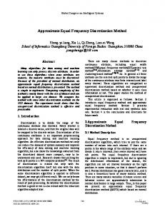
the advantage of this allocation is the preservation of the interrelation between the integrals over areas and the line integrals in Maxwell's equations. For the triangular mesh, we proceed in an analogous way. But here we must distinguish two cases: (i) If all triangles of the mesh inside the cavity have angles less than or equal to Jr/2, we choose as dual mesh lines the perpendicular bisectors of the sides (see Figs. 5 and 6). These intersect in the center of a circle drawn through the three vertices of the triangle. (ii) The program starts with a mesh of regular triangles and varies it in order to approximate the given boundaries as well as possible. In this process, it cannot always avoid triangles with an angle larger than Jr/2. If this happens, the use of the above-defined dual mesh points would lead to the following problem: Some dual mesh points are outside the proper triangles (Fig. 7). In this case we use the centers of mass as dual mesh points. It should be noted that the F component in this dual mesh is in general not perpendicular to the F component (see Fig. 8). In the following, we will denote the dual mesh with perpendicular bisectors for sides as G M , that with centers of mass as G s , and the triangular mesh as G. The numbering of mesh points and the allocation of the triangles to these points is explained in the following. The numbering of the mesh points is done analogously to URMEL, as may be seen in Fig. 9. This picture also demonstrates that there are two kinds of triangles alternating in the rows: One has the vertex on top,
FIGURE 5 Triangular mesh and its dual (hexagonal) mesh with Ea, Eb , Eo EqJ and Ba, Bb , Bo BqJl' Bqy2 •
TRIANGULAR DISCRETIZATION
243
FIGURE 7 An obtuse triangle, showing that the center of the circumscribed circle lies outside the triangle.
FIGURE 8 Dual mesh with centers of mass as mesh points; (F, F) = (E, B) or (H, D).
while the other one is standing upright. One of each kind is associated with each mesh point k [k = (j - 1) . J + i with j = 1, ... ,J, i = 1, ... ,I]. The triangle of the first kind is named (1, k) and the second (2, k). As Fig. 9 demonstrates, the order of the triangles starts with one of the first kind in the rows with an odd j and with one of the second kind in all rows with an even j. Figure 10 shows for a general mesh point k all adjacent triangles, triangle sides, and mesh points. Evidently, a part of this is absent for boundary points. In some places in the formulas, in the following sections and in the appendix, superposed indices are used. The upper one always refers to the formula for a point k = (j - 1) . J + i in row j with even j (type I), while the lower one refers to the formula for k in row j with odd j (type II). The allocation of all the field components, associated with a mesh point, is illustrated in Fig. 11 for the points l of type I and k of type II.
u. VAN
244
RIENEN AND T. WEILAND
J + 1l----"""*-------¥---~--~--~:______i
FIGURE 9 Numbering of the mesh points.
J +J
.l +J +1
a(L+J) (2,l)
c(k-1)
b(L)
c(k)
(1, k-1l
k-l
(1,k)
a(k-1)
k
a(k)
(2,k-J-1) b(k-J-1)
b(l+ 1)
k+1
(2, k - J)
c(l-J)
b(k-J)
c(t-J+f)
(1,1- J )
L -J
a (l-J )
with k = ( j - 1) . J
1-J +1
+
i
and 1. ={ k }for { ~ even} k-1
J odd
FIGURE 10 Points, sides, and triangles adjacent to a mesh point.
245
TRIANGULAR DISCRETIZATION
triangle (1,k)
triangle (2. k)
triangle(2,i)
row j with j even
triangle (1.1)
FIGURE 11 Location of the field components and the triangles associated with one mesh point.
2.2. Allowed Material Properties in the Different Grids
As mentioned above, the permittivity and the permeability shall be real. For G M as dual mesh, any inserted material may have I-lr =1= 1 and E r =1= 1 and either E or H could be chosen for F (see Figs. 12 and 13). In Fig. 12, it may be seen that only continuous components (Le., tangential E and normal B) occur, so that triangles of G may be filled with materials with I-lr =1= 1 and E r =1= 1 and varying from triangle to triangle. Similarly, in Fig. 13, only tangential H and normal D occur at the triangle boundaries. If only the dual mesh G s can be used, we have to place a restriction to assure the continuity of the field components: Only insertions with I-lr =1= 1 but E r = 1, or E r =1= 1 but I-lr = 1 are allowed, and F will be taken as shown in Figs. 14 and 15. In Fig. 14, it is seen that (continuous) tangential E occurs at the triangle interfaces, and so E r can vary from triangle to triangle. However, since on the dual mesh the magnetic field component is not normal to the interfaces, I-lr can not vary from
246
u. VAN
RIENEN AND T. WEILAND
FIGURE 13 H on G, D on G M , !-lr =1= 1,
E r =1=
FIGURE 14 E on G, B on G s , !-l = !-la,
1.
FIGURE 15 H on G, D on G s , !-lr =1= 1,
E
E r =1=
1.
= Eo-
triangle to triangle. Similarly, in Fig. 15, it can be seen that, with H on the mesh G, IJr can vary whereas E r cannot. Although the constants lJo and Eo are shown' in Figs. 14 and 15, in fact if the cavity or waveguide were completely filled with a medium with constant IJr or constant E r , respectively, only continuous field components would occur. However, for nearly all structures, it is possible to find a mesh which renders G M possible as a dual mesh.
2.3. Deflecting Modes, m > 0 With the given assumptions, the electromagnetic fields can be written as 00
E(r, cp, z, t)
= ~ sin rot L
[Em,r(r, z) cos mcper
m=O
+ Em,cp(r, z) sin mcpecp + Em,z(r,z) cos m 0, a linear eigenvalue problem [Eq. (13)] is to be solved. The
U. VAN RIENEN AND T. WEILAND
250
FIGURE 18 Connection of equations.
F(f)l (upper figure) and F(f)2 to three neighbors by the difference
eigenvectors are now X
=
T (F