Trigger Algorithm Development on FPGA-based Compute Nodes Ming Liu1,2 , Axel Jantsch2 , Dapeng Jin3 , Andreas Kopp1 , Wolfgang Kuehn1 , Johannes Lang1 , Lu Li3 , Soeren Lange1 , Zhen’an Liu3 , Zhonghai Lu2 , David Muenchow1 , Vladimir Pechenov1 , Johannes Roskoss1 , Stephano Spataro1 , Qiang Wang1,3 , Hao Xu3 1. II. Physics Institute, Justus-Liebig-University Giessen, Germany 2. Dept. of Electronic, Computer and Software Systems, Royal Institute of Technology, Sweden 3. Experimental Physics Center, Institute of High Energy Physics in Beijing, China
Abstract—Based on the ATCA computation architecture and Compute Nodes (CN), investigation and implementation work has been being executed for HADES and PANDA trigger algorithms. We present our designs for HADES track reconstruction processing, Cherenkov ring recognition, Time-Of-Flight processing, electromagnetic shower recognition, and the PANDA straw tube tracking algorithm. They will appear as co-processors in the uniform system design to undertake the detector-specific computing. The algorithm principles will be explained and hardware designs are described in the paper. The current progress reveals the feasibility to implement these algorithms on FPGAs. Also experimental results demonstrate the performance speedup when compared to alternative software solutions, as well as the potential capability of high-speed parallel/pipelined processing in Data Acquisition and Trigger systems.
I. I NTRODUCTION
M
ODERN nuclear, hadron and particle physics experiments, for example HADES [1] and PANDA [2] at FAIR, are expected to run at a very high reaction rate (HADES, 100 KHz; PANDA, 10-20 MHz) and able to deliver a data rate of up to hundred GBytes/s (HADES, up to 10 GBytes/s; PANDA, up to 200 GBytes/s). Among the huge amounts of events, only a rare proportion is of interest due to its particular physics contents and should be selected for in-depth physics analysis. Besides, all the events cannot be entirely stored because of the storage limitation. Therefore it is essential to realize an efficient on-line data acquisition (DAQ) and trigger system to process and filter events. As a result, the data rate to be stored can be reduced by several orders of magnitude. Depending on the physics focus of the experiment, sophisticated real-time pattern recognition algorithms such as Cherenkov ring recognition, particle track reconstruction, Time-Of-Flight (TOF) analysis, Shower recognition [3] [4] [5] and high level correlations are implemented for recognizing the interesting data. Only the events which meet expected patterns and correlations receive a positive decision and will be forwarded to the mass storage for later off-line analysis. Others are discarded on the fly. To meet the data processing requirements of modern experiments, we have designed and built a high-end reconfigurable Corresponding author’s address: Ming Liu, II. Physikalisches Institut, Heinrich-Buff-Ring 16, D-35392, Giessen, Germany; E-mail:
[email protected]
computation platform as the solution. The system architecture features interconnected Compute Nodes (CN), utilizing the cutting-edge ATCA communication standard and FPGA technologies. Point-to-Point (P2P) on-board and ATCA backplane channels enable the high bandwidth needed by algorithms or algorithm steps for data exchanging; FPGA reconfigurability provides the possibility to develop customized hardware modules for accelerating different pattern recognition algorithms. Based on the CN and the FPGA design flow, we have been being developed multiple algorithms for HADES and PANDA data acquisition and triggering. The detailed design and experimental results will be elaborated in the following sections. The remainder of the paper will be organized as the following: In Section 2, previous algorithm implementations are addressed as sample solutions. The interconnection architecture, CNs and FPGA system designs will also be introduced for the DAQ and trigger systems in HADES and PANDA experiments. In section 3, concrete pattern recognition algorithms for HADES upgrade are presented, including track reconstruction processing, Cherenkov ring recognition, Time-OfFlight processing, electromagnetic shower recognition. Design consideration is analyzed, and experimental results reveal the feasibility and performance benefits of the hardware online processing. In Section 4 the Straw Tube Tracking (STT) for PANDA is briefly introduced. Finally we come to the conclusion and propose our future work in Section 5. II. R ELATED W ORK A. Trigger Algorithm Implementations Trigger algorithms identify specific patterns out of massive background data to decide interesting events. Traditionally the implementation is divided into two approaches: offline software solutions on PC clusters and online embedded computation on such as FPGAs or DSPs. By contrast, offline software processing on PC farms is easily implemented by high-level programming. It can also achieve sophisticated calculation for extensive feature extraction. However offline processing needs all data to be stored and does not contribute to data rate reduction for mass storage. Modern nuclear, hadron and particle physics experiments feature high reaction rate and high data rate, which is not possible to be entirely stored.
Furthermore, as the rapid development of FPGA technologies on the reprogrammable resource capacity and the communication bandwidth, it is feasible to migrate some software implementations into the FPGA fabric for online triggering, increasing the data reduction rate for storage and accelerating the pattern recognition processing with customized hardware designs. For example in the original HADES DAQ and trigger system [3] [4], online Level-2 trigger algorithms were implemented as embedded designs on FPGAs and DSPs, including the RICH Image Processing Unit (IPU), the TOF IPU and the Shower IPU. Whereas the MDC tracking processing was designed as software programs on desktop PCs, due to the algorithm complexity for hardware implementation. In the HADES upgrade project for heavier ion reactions, we will try to implement the MDC tracking algorithm as well as others on FPGAs for high processing performance and event selection efficiency. B. Compute Node for DAQ and Trigger As a general-purpose solution for data acquisition and trigger applications in various physics experiments, a computation platform of interconnected nodes has been developed based on the ATCA communication standard [6]. To simultaneously satisfy different algorithm partition and correlation requirements for current or future experiments, the full-mesh Point-to-Point (P2P) backplane has been chosen to interconnect multiple FPGA-based CNs for massive parallel processing. The network topology is demonstrated in Figure 1. We observe that external channels, specifically optical links as well as Gigabit Ethernet, are engaged in receiving sub-events from detectors and forwarding processing results to the PC farm for mass storage and offline analysis; Internal hierarchical interconnections, including the inter-chassis optical link and Ethernet switching, inter-board full-mesh backplane connections, on-board FPGA I/O channels, are utilized to partition and distribute algorithms or algorithm steps for parallel/pipelined trigger processing and correlation. In the ATCA crate, CNs appear as Field Replaceable Units (FRU), which are interconnected with each other by backplane channels. On each CN, five Xilinx Virtex-4 FX60 FPGAs are placed on board and mutually interconnected by General-Purpose I/O (GPIO) buses as well as RocketIO serial links. Four FPGAs work as algorithm processor nodes, and the fifth one as the switch interfacing the CN PCB to the backplane. The schematic of the CN is shown in figure 2, with the memory, communication channels and peripherals integrated. Detailed architectural description on the ATCA computation platform and the CN design can be referred to in [7]. C. System-on-an-FPGA Design A System-On-Chip (SOC) design architecture is fitted on each FPGA node, as shown in Figure 3. On each FPGA, the complete computer system contains both general components (CPU, memory, peripherals, ...) and customized algorithm processing modules (tracking, shower recognition, ring recognition, ...). The PowerPC 405 processor runs an embedded Linux
Fig. 1.
Computation network for online pattern recognition
Fig. 2.
Compute node schematic
OS to manage all peripherals and realize slow controls during experiments [11]. Algorithm processors are implemented in the FPGA fabric for hardware acceleration. To improve the memory access capability of the algorithm processors, they are directly interfaced with one port of the Multi-Port Memory Controller (MPMC). The system design is expected to be uniform, and only the customized processors will be exchangeably equipped for respective algorithm computation. We will introduce the customized designs for different pattern recognition processors in the following sections. III. T RIGGER A LGORITHM D EVELOPMENT FOR HADES U PGRADE A. HADES Detector System The High Acceptance Di-Electron Spectrometer (HADES) [1] is installed at the heavy ion synchrotron of the GSI facilities in Darmstadt, Germany. Its main objective is the measurement of lepton pairs (dileptons)
higher timing resolution. All the detectors consist of 6 assembled trapezoidal sectors. When the accelerated beam particles collide the target, product particles will be emitted, and they fly through these detectors and generate signals on them. B. MDC Track Reconstruction Algorithm
Fig. 3.
MPMC-based hardware design with P2P switching connections
produced in the decay of light vector mesons at a reaction rate of less than 106 Hz with an accuracy of 4p p ' 1% particle momentum resolution [8][9]. The HADES spectrometer is composed of several different specialized particle detectors, as shown in Figure 4(a) for exploded view, Figure 4(b) for mounted shape, and Figure 4(c) giving a lateral cut view.
(a) Exploded exhibition of the HADES detector system
(b) HADES detector system view when mounted Fig. 4.
(c) Lateral cut view of the HADES detector system
The HADES detector system
From the figures, we see in the HADES spectrometer, there have been RICH, MDC, TOF, TOFino, Shower detectors installed. In the upgrade project, the RPC detector will also be mounted as the replacement of the TOFino detector for
The HADES Mini Drift Chamber (MDC) tracking system consists of four MDC modules (2 before and 2 behind the magnetic field inside the superconducting coils), which have six identical trapezoidal sectors. Before and after the coil, the magnetic field does not penetrate into the MDCs in first approximation. Hence two segments can be reconstructed separately with the inner (I - II) and the outer (III - IV) MDC information. The basic principle is similar and in this article we focus only on the inner part. In the two inner MDC modules, a total number of 12660 sense wires (6 sectors) are arranged in 12 layers and 6 orientations: +40◦ , -20◦ , 0◦ , 0◦ , +20◦ , -40◦ . when beam particles hit the target, charged particles are emitted from the target position and go forward through different wire layers in straight paths. Along their paths, signals are generated on sense wires close to the tracks with high probability (>95%). Shown in Figure 5, if the sensitive volumn of each wire is projected from the boundary of the target onto a plane located between two inner chambers, apparently the particle passed through the projection plane, at the point where all projections of fired wires from different layers overlap. To search for such regions the projection plane is treated as a two dimensional histogram with the projection area as bins (pixels). For each fired sense wire, its projection bins are all increased by one. By finding the locally maximum bins whose values are also above a given threshold, track candidates can be recognized and the tracks are reconstructed as straight lines from the point-like target to those bins. Figure 6(a) demonstrates the 2D projection plane for one sector with 2 passed particles. Figure 6(b) is the 3D display of Figure 6(a) for a single track, where the coordinates of the peak in the center are recognized as the track’s position. The Tracking Processing Unit (TPU) has been designed for online particle track reconstruction during experiments. The modular structure and system interfaces are demonstrated in the block diagram in Figure 7. MDC sub-events of fired wire numbers are first introduced from detectors by RocketIObased optical links and buffered in the external DDR2 memory (shown by step 1 in the figure). Then by either the processor or DMA, the fired wire information is supplied to a FIFO in the TPU design for pattern recognition calculation (step 2). To determine which bins on the projection plane will be touched by the projection shadow of fired wires, realtime calculation is hard for implementation and thus should be avoided due to the geometrical complexity. Instead an offline built projection LUT is used to store this information, with serial numbers of wires as the entry. Another address LUT derives some storage address information to the bus master as well as the accumulate unit. In practice, the resolution of the projection plot is selected as 128 x 256 bins per sector. The projection LUT is about 1.5 MBytes and must be initialized in DDR2. The address LUT is small and can be fitted in the Block RAM
Fig. 7.
Block diagram of the TPU structure
Resources
Fig. 5.
800
12
700
10
600
8
500
6
4-input LUTs Slice FlipFlops Block RAMs
12 10
6
4
300
2
6210 out of 50560 (12.3%) 2966 out of 50560 (5.9%) 45 out of 232 (19.4%)
10698 out of 50560 (21.2%) 9035 out of 50560 (17.9%) 53 out of 232 (22.8%)
MPMC-based system with the TPU 16908 out of 50560 (33.4%) 12001 out of 50560 (23.7%) 98 out of 232 (42.2%)
TABLE I R ESOURCE UTILIZATION OF THE MPMC- BASED SYSTEM AND THE TPU
8
400
MPMC-based system (no application processor)
Event 74 Sector 4
Event 74 Sector 4 y, (mm)
TPU module
Track recognition and reconstruction in inner MDCs
4 2 0
50 660
y, (m 640 m) 200
-400
-300
-200
-100
0
100
200
300
400
0
620
600
580
560
540
0 -50 -100 -150 -200 -250
x,
150 100
(m
m)
x, (mm)
(a) Projection plane with two passed (b) 3D display of the accumulated tracks bins for a single track Fig. 6.
Particle tracks in the projection plane of one sector
on the FPGA. With the projection LUT data fetched by the bus master (step 3), the accumulate unit accumulates the histogram of touched times by fired wires for all projection plane bins. Temporary sums are recorded in a dual-port RAM block on the FPGA. After the accumulation of all fired wires in one subevent, the peak finder compares the bins in the neighbourhood and figures out the exact peak where particles most probably passed through. Detailed design description could be referred to in [10] The TPU design is based on VHDL and implemented on FPGA using Xilinx EDK and ISE software. Its resource consumption statistics are shown in Table I, as well as the utilized percentage of Xilinx Virtex-4 FX60. Considering the entire system design (depicted in Figure 3) which hosts application-specific modules, statistics for the MPMC-based FPGA design are respectively listed in the table as well, with and without TPU integrated. We observe that 12.3% LUT resource and 5.9% Flip-Flops are regulated to construct the computational logic and registers in TPU. In addition 19.4% Block RAM resource is dedicated to the storage components shown in Figure 7 as grey blocks. The last column in the table indicates the resource consumption of the entire system with
one TPU integrated. From the figures we conclude that the total resource utilization is acceptable, and it is feasible to implement the online inner track reconstruction computation on the Virtex-4 FX60 FPGA. The timing summary shows that the TPU design can maximumly run at 125 MHz without further optimization effort. To match the speed of the MPMC port and the PLB bus, we fix its clock frequency at 100 MHz. We measured the processing capability of the TPU module in the following experimental setup: One TPU is incorporated in the system design. It runs at 100 MHz, as well as MPMC ports. The MPMC core and the DDR2 memory run at 200 MHz. Large amounts of randomly generated wire numbers are initialized in the DDR2 memory as input, to simulate incoming MDC sub-events through optical links. In case of heavy ion reactions, which imply more emitted particle tracks from the target and hence more fired wires in each MDC sub-event, it takes more clock cycles to fetch the Projection LUT data and execute the track reconstruction processing. Therefore we took into account the number of fired wires in each sub-event and measured the processing speed of the TPU module at five wire multiplicities, specifically 10, 30, 50, 200, and 400 fired wires in a single sub-event. The results demonstrate the processing capability of 32.3, 12.2, 7.5, 2.0, 1.0 KSub-events/s respectively. Compared to a software prototype in C program, which runs on one core of the Intel Xeon 2.4 GHz CPU server with the Gentoo Linux OS, the measured results are shown in Figure 8. This reveals a highest hardware acceleration of 24.3 times for light ion reactions and a lowest one of 10.8 times
Fig. 8.
HW & SW processing capability of MDC sub-events
Fig. 9.
Speedup of the TPU module over SW solution
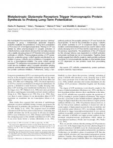
for heavy ion reactions. The processing speedup of the TPU design over the software solution is listed in Figure 9 at five assumed wire multiplicities. C. RICH Ring Recognition Algorithm The HADES Ring Image CHerenkov (RICH) detector is used to identify dilepton pairs with the Cherenkov light reflected at the mirror. The ring pattern is searched on a detector plane with the resolution of 96 x 96 pads. The Cherenkov ring features a constant diameter of 8 pads on the plane, and the pattern search is executed within a fixed mask reagion of 13 x 13 pads, as shown in Figure 10. The hits on a ring with a radius of 4 pads are added to the value ring region. There are two veto regions inside and outside the ring region, where the pads are also added. Thus the ring pattern is identified if both the ring region sum is above and the veto region sum is below their respective thresholds Due to the constant diameter of the ring pattern, the computation challenge falls on the position identification of ring centers. To simplify the algorithm and correlate the RICH pattern with the MDC tracking information, inner particle tracks are introduced in the Ring Processing Unit (RPU) to specify potential ring centers. The correlation between MDC and RICH can be observed in Figure 11 in inner detectors
Fig. 10.
Fixed-diameter ring recognition on the RICH detector
Fig. 11.
Inner and outer detector correlation in HADES
before the magnetic field. To convert the coordinate and the granularity from MDC into RICH, a LUT is employed to derive a region of potential ring candidates. With the implied center, the ring pattern search is carried out by accumulating the sums of the ring region and the veto regions. Figure 12 shows the block diagram of the RPU design in the FPGA fabric. It will also appear as a customized co-processor integrated in the FPGA system design. D. Shower Recognition and TOF Processing The electromagnetic shower is introduced by electrons in the lead converters, increasing the number of charged particles. The Shower processor finds electron signatures in the three layers of the Shower detector [4]. It searches for the increasement in charge in the deeper layers, which is done by adding the charge in 3 x 3 pad regions (see Figure 13). Similar to the RICH ring recognition, local peak search will be executed in parallel and pipelined fashion on FPGAs. The TOF detector selects electrons by discriminating particles by their velocities. Hence the time-of-flight from the target to one scintillator stripe is measured to calculate the velocity. The computation mainly concerns floating-point calculations, which was previously implemented on DSP processors in software. On the CN platform, this work will be re-designed
Fig. 12.
Block diagram of the RPU design
Fig. 13.
Shower pattern in 3 x 3 pad regions
on FPGAs using the DSP slice resource. Parallel architectures are expected to achieve performance speedup as well as more efficient I/O operations for correlating with other algorithms. The Shower and the TOF detectors are jointly called META detectors (see Figure 11). Similar to the inner part consisting of the RICH and the inner MDCs, the outer MDC tracks will be extrapolated and point to META detectors. The track information will be useful and help TOF and Shower to find respective patterns. For example in Figure 14, MDC tracks are utilized to provide pattern candidates on the Shower detector. The correlation will be done on CNs by message passing between algorithm processors. E. Parallel Processing Architecture Analysis The HADES upgrade project features the reaction rate of 100 KHz maximumly, implying the MDC data rate of 100 KSub-events/s. For each sector (6 in total), it is about 17 KSubevents/s. Evaluating the practical average wire multiplicity of 50 fired wires per MDC sub-event and observing the hardware processing speed in Figure 8, roughly 4 inner and 4 outer TPU modules are sufficient to manage the data rate of 17 KSub-events/s for each sector. We evenly distribute the
Fig. 14.
Shower patterns correlated to MDC tracks
Fig. 15.
Algorithm partition and distribution on two CNs for one sector
8 TPU cores on different FPGAs of 2 CNs and mix with other algorithm processors, as shown in Figure 15. Algorithms mutually correlate their processing results via on-chip, onboard or ATCA backplane interconnections. In summary, 12 CNs plus one redundant board are scheduled for 6-sector processing in the HADES upgrade. IV. T RIGGER A LGORITHM D EVELOPMENT FOR PANDA PANDA is a future project at FAIR. We have started the helix tracking investigation and will implement the algorithm on FPGAs for online processing in the experiment. The motivation is to recognize helical particle tracks in the Straw Tube Tracker (STT) detector, in which tracks appear as circular arcs in a 2-dimension x-y coordinate (see Figure 16(a)). To recognize circle patterns, we convert them into lines (Figure 16(b)) by Conformal Transformation [12]. With further Hough Transformation [13], lines are converted into respective peaks (Figure 16(c)) in the parameter space which are much easier to be recognized. The formulas of the transformations are deduced as the following: To transform the x-y coordinates into a conformal space where circles go into staight lines, the
optimize the system architecture and realize synchronous message passing for algorithm correlation, is helpful to improve the overall performance of the DAQ and trigger system. ACKNOWLEDGMENT This work was supported in part by BMBF under contract Nos. 06GI179 and 06GI180, and by FZ-Juelich under contract No. COSY-099 41821475. (a) Partcle tracks in real space
(b) Transformations space
in
conformal
(c) Patterns in parameter space Fig. 16.
Conformal and Hough transformations to recognize particle tracks
following calculation has to be done: x − x0 y − y0 x0 = y0 = r2 r2 r2 = (x − x0 )2 + (y − y0 )2 where (x0 , y0 ) is the reference point for the transformation, and r is the distance between the reference point and the current point to be transformed. In the next step in the Hough Transformation the coordinate points will be described by x · cos ϑ + y · sin ϑ = r where r is the distance between a line and the origin and ϑ is the orientation angle of the line. To register the possible r and ϑ in the parameter space will cause searching for peaks in the next step. On the Xilinx FPGA, the transformation calculations are to be done with the DSP slices (multiplication and addition) and various mathematic operation IP cores. The peak finding step is realized by comparing with thresholds and neighbour values. V. C ONCLUSION AND F UTURE W ORK In this paper, we have presented multiple trigger algorithms for the HADES upgrade and the PANDA construction projects. Based on the compute node design, all algorithms are being implemented in the FPGA fabric for online hardware processing. They appear in the SOC system design as customized processors to calculate specific detector sub-events for desired patterns, and mutually correlated by message passing. Future work includes how to effeciently and evenly utilize FPGA resources during the hardware implementation. Also, to
R EFERENCES [1] High Acceptance Di-Electron Spectrometer (HADES) @ FAIR, GSI, Darmstadt, Germany, www-hades.gsi.de. [2] antiProton ANnihilations at DArmstadt (PANDA) @ FAIR, GSI, Darmstadt, Germany, www.gsi.de/panda. [3] I. Froehlich, A. Gabriel, D. Kirschner, J. Lehnert, E. Lins, M. Petri, T. Perez, J. Ritman, D. Schaefer, A. Toia, M. Traxler, and W. Kuehn, “Pattern recognition in the HADES spectrometer: an application of FPGA technology in nuclear and particle physics”, In Proc. of the 2002 IEEE International Conference on Field-Programmable Technology, pp. 443444, Dec. 2004. [4] M. Traxler, “Real-time dilepton selection for the HADES spectrometer”, November 2001, Ph.D thesis, II.Physikalisches Institut, Justus-LiebigUniversitaet Giessen. [5] C. Hinkelbein, A. Kugel, R. Manner, M. Muller, M. Sessler, H. Simmler and H. Singpiel, “Pattern recognition algorithms on FPGAs and CPUs for the ATLAS LVL2 trigger”, IEEE Transactions on Nuclear Science, Volume 48, Issue 3, Part 1, pp. 296-301, Jun. 2001. [6] PCI Industrial Computers Manufactures Group (PICMG), “PICMG 3.0 Advanced Telecommunications Computing Architecture (ATCA) specification”, Dec. 2002. [7] M. Liu, “ATCA-based Computation Platform for Data Acquisition and Triggering in Particle Physics Experiments”, In Proc. of the International Conference on Field Programmable Logic and Applications 2008, pp. 287-292, Sep. 2008. [8] HADES collaboration, “A proposal for a High Acceptance Di-Electron Spectrometer”, 1994, GSI Darmstadt. [9] Daniel Kirschner, “Level 3 Trigger Algorithm and Hardware Platform for the HADES Experiment”, Oct. 2007, Ph.D thesis, II. Physics Institute of Justus-Liebig-University Giessen. [10] M. Liu, W. Kuehn, Z. Lu, A. Jantsch “System-on-an-FPGA Design for Real-time Particle Track Recognition and Reconstruction in Physics Experiments”, In Proc. of the 11th EUROMICRO Conference on Digital System Design, pp. 599 - 605, Sep. 2008. [11] Qiang Wang, Axel Jantsch, et al., “Hardware/Software Co-design of an ATCA-based Computation Platform for Data Acquisition and Triggering”, In Proc. of the 16th IEEE NPSS Real Time Conference, May. 2008. [12] E. P. Dolzhenko, “Conformal Mapping”, in Hazewinkel, Michiel, Encyclopaedia of Mathematics, Kluwer Academic Publishers, ISBN 9781556080104. [13] R. O. Duda and P. E. Hart, “Use of the Hough Transformation to Detect Lines and Curves in Pictures”, Communications of the ACM, volume 15, issue 1, pp. 11 - 15, Jan. 1972.