250 nodes per access point, thousands of nodes with multiple access points, radio ... Wireless Sensor Networks, Time Synchronization, Mesh. 1. INTRODUCTION ... frequency-diverse advantages compared to a single- channel solution. First ...
Proceedings of the IASTED International Symposium Distributed Sensor Networks (DSN 2008) November 16 - 18, 2008 Orlando, Florida, USA
TSMP: TIME SYNCHRONIZED MESH PROTOCOL Kristofer S. J. Pister, Lance Doherty Dust Networks 30695 Huntwood Ave., Hayward, CA 94544 USA {kpister,ldoherty}@dustnetworks.com
ABSTRACT The Time Synchronized Mesh Protocol (TSMP) enables reliable, low power, secure communication in a managed wireless mesh network. TSMP is a medium access and networking protocol designed for the recently ratified Wireless HART standard in industrial automation. TSMP benefits from synchronization of nodes in a multi-hop network to within a few hundred microseconds, allowing scheduling of collision-free pair-wise and broadcast communication to meet the traffic needs of all nodes while cycling through all available channels. Latency and reliability guarantees can be traded off for energy use, though our focus has been on providing high reliability (>99.9%) networks at the lowest power possible. TSMP has been demonstrated in multi-hop networks exceeding 250 nodes per access point, thousands of nodes with multiple access points, radio duty cycles of 0.01%, and with devices at radically different temperatures and traffic levels. With the 802.15.4 physical layer and 10 ms time slots, TSMP can theoretically achieve a secure payload throughput of 76 kbps at a single egress point.
and many groups have demonstrated the superior performance that it affords [4, 5, 6]. TSMP, in production since 2004, is the first WSN protocol to use time synch to schedule collision-free channel hopping communication. Perhaps also novel, and certainly contrary to conventional wisdom in the WSN community, TSMP was developed to be used in a managed network with a centralized controller that coordinates the communication schedule for the network. A managed network has the prime benefit that each channel in the spectrum can be used without concern for collisions or wasteful overhearing of packets. Network management is sometimes dismissed on the grounds of lacking scalability and robustness, and confusion over the viability of network-wide synch. However, implementation and testing of TSMP over several product generations has shown that these criteria can be met (and to date have only been met) in a managed network. In particular, TSMP has been targeted to: 1. Reliability at low-power: >99.9% packet delivery with years of battery life for all nodes 2. Scalability: hundreds of meshed nodes per manager, thousands in the same RF environment 3. Flexibility: support different time-varying traffic patterns from different nodes 4. Security: guarantee confidentiality, integrity, and authenticity of all packets 5. Environment: nodes operate between -40°C and 85°C and in radically changing RF noise levels TSMP provides a framework for the association of layer 2 resources with layer 3 routes and layer 4 Quality of Service (QoS). Standards specify packet formats and layered transaction models for the pair-wise communication and how multi-hop routes are maintained to a management application. It remains the duty of the network designer to assign data flows based on service requests from nodes and reports on how successful the wireless paths have been.
KEY WORDS Wireless Sensor Networks, Time Synchronization, Mesh 1. INTRODUCTION Additional to Wireless Sensor Network (WSN) research topics, a growing commercial and industrial application space now exists. These applications require reliable, timely, secure delivery of packets at low power. A survey of the research literature suggests similar objectives [1]. Diligent attention to these requirements led to the development of TSMP, the Time Synchronized Mesh Protocol. The potential of this approach is evident in its recent adoption as the basis for the Wireless HART [2] and ISA100 protocols. Both protocols are intended for industrial automation where applications are extremely performance-sensitive; TSMP’s adoption in this regime came only after extensive evaluation in hundreds of realworld deployments over a period of a several years. The cornerstones of TSMP performance are network-wide time synch, channel hopping, dedicated slotted unicast communication bandwidth, link-layer ACKs, graph-based routing, and multi-layer security on every packet. Much work has been done on time synch in sensor networks [3], 635-800
2. DIVERSITY TSMP provides reliable data transfer by combining time, frequency, and routing diversity. All nodes in a TSMP network share the same sense of time, accurate to < 1ms. This capability allows time-diversification by scheduling different transmissions to occur during non-overlapping
391
time channel offset
intervals and thus conserve energy by avoiding collisions. When nodes agree on when communication could occur, both sides of a radio link can reduce their “on time”. We will show that the cost of maintaining this synch is small and compares favorably to asynchronous protocols [7,8]. There is no additional preamble used in TSMP transmission beyond the physical-layer (PHY) requirements, and a low idle listen cost is achieved with a short 2ms guard time. Also, it is trivial for sensors attached to time-synched nodes to time-stamp their data. Packet delivery rates on different channels for the same node pair can vary wildly, as can a single channel over time [9]. By adding channel hopping in addition to Direct Sequence Spread Spectrum (DSSS), TSMP offers frequency-diverse advantages compared to a singlechannel solution. First, it increases the network bandwidth linearly in the number of channels. Second, it increases reliability by having each node pair communicate on all potentially good channels decreasing the chance of terminal loss of connectivity. Third, since multi-path fading is frequency-dependent, using more channels increases the effective radio range. TSMP channel hopping is similar to the strategy in [10] to mitigate interferers in 802.11 devices as DSSS alone is insufficient to overcome the deep fades of multipath interference [11]. Lastly, hopping makes TSMP more robust to interference and reduces the impact on other wireless networks. To provide different levels of QoS, TSMP radio resources and packet flows are organized into independent graphs similar to MPLS labels, ATM circuits, or IPv6 flow labels. The flows travel along routing-diverse meshes: packets generally have more than one possible next hop at each step along their multi-hop route which insulates against single-device failure and congestion.
…
timeslot
Superframe
Figure 1. Slot-Channel Matrix for a network with 5 channels. Each cell can contain one transaction. AP
AP
AP
C
D
C
D
C
D
A
B
A
B
A
B
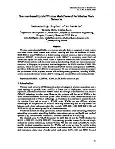
Figure 2. Simple graphs. Left: collection mesh from all nodes to the AP. Middle: broadcast mesh from the AP to all nodes. Right: multicast mesh from the AP to three nodes, and a peer-to-peer mesh from A to D. A graph is a routing structure that forms directed end-toend connections among devices. For example, a datacollecting graph could join all nodes in the network to the Access Point (AP) where payloads are forwarded to the user. Some simple graphs are shown in Figure 2. Each destination will generally have its own graph, but several sources can share the same graph. In this context, a destination could be a single node or a set of nodes. A functional graph is composed of pair-wise paths that connect each source to the destination directing the packet at each hop along the way. A typical unidirectional graph terminates only at the destination and does not have loops. A single network generally has multiple graphs, some of which overlap and each individual device can have multiple graphs associated with each of its neighbors. The basic graphs used in TSMP are upstream and downstream meshes: upstream to route packets one hop closer to the manager with each transaction and downstream to route from the manager to all nodes. A downstream graph in this case can implement network broadcast or multicast, where the destination is “all”, and allows both source routing and flooding to occur on the same links. When a packet is originally created at its source, the application layer identifies its flow (final destination and QoS) and supplies it with a fixed Graph ID that will guide it along its multi-hop route to the destination. In a mesh graph, it is possible that multiple next hops are specified at any particular node; redundancy is directly built-in. A superframe is a collection of cells repeating at a constant rate. Events are scheduled to happen in individual cells in a superframe and the network is configured to support these events with periodicity equal to the superframe length. With a 10ms slot, a cell in a 1000-slot superframe repeats every 10s. A cell in a shorter superframe is representative of more bandwidth as it repeats more frequently. In TSMP, the superframe is the translation of the logical data-flows of the graph into the
3. PROTOCOL STRUCTURE TSMP works by providing a bridge between the physical domain of wireless communication and the logical domain of network-wide data flows. Physically, the wireless channel is divided up in time and frequency and each resulting unit of the channel is assigned to satisfy data flow requirements. Logically, data flows from hop to hop along pre-defined routes from source to destination. Time is divided up into discrete time slots (10ms in this paper) long enough for any single transaction. The longest transaction is one where the sender transmits the maximum length packet and the receiver acknowledges it. Every node in the network must agree on the number of time slots since the beginning of the network (the Absolute Slot Number, or ASN). TSMP is designed to operate on multiple channels. Based on shared ASN, each packet is sent on a pseudo-random channel. This paper uses 2.4GHz channels from the IEEE 802.15.4 standard, each with ~2MHz of DSSS bandwidth. TSMP models RF space as a matrix of slot-channel cells (Figure 1). Transactions scheduled in different cells are guaranteed to not interfere with each other. The slotchannel matrix extends from ASN=0 to infinity. 392
physical communication schedule for the network. Typically, a network will have several graphs with different superframe lengths. In a network of a single superframe, however, a no-collision guarantee can be trivially made by assigning only one event per cell. For example, the periodically populated shaded cells in Figure 1 show four cycles of a four-slot superframe (16 slots). A link is an event scheduled in one cell. It consists of a superframe ID, source and destination IDs, a slot number referenced to the beginning of the superframe, and a channel offset. The simplest version is a dedicated link: one transmitter and one receiver. Here, two nodes communicate periodically once per superframe. If only one transmitter is scheduled, the link is contention-free but Slotted Aloha can be implemented by scheduling multiple transmitters in a single link with a backoff algorithm after packet failures. Either of these two schemes can unicast packets to a single receiver allowing an ACK for timing or reliability purposes. Multipledestination broadcast links are used for quick low-power distribution of packets to several children and work well for flooding nodes along a particular graph. Each time a link arises in a superframe, nodes scheduled to be receivers on this link are required to turn on their radios and await a potential packet from the sender. The senders only initiate transmission if there is a packet waiting for transmission on the graph to which the link belongs. TSMP links hop pseudo-randomly over a set of channels one packet at a time. Each time a link fires, both sides of the link calculate the radio channel of the communication: Ch = LUT( (ASN+offset)%NumCh ) • Ch is the channel number • Offset is the link’s y-value in the slot-channel matrix • NumCh is the number of available channels • LUT is a look-up-table with a static pseudo-random mapping between the inputs from 0 to NumCh-1 • ASN is the absolute slot number For example, in a monotonic LUT={0, 1, …, 15}, a series of links with consecutive slots and constant offset will cycle through the channels in series, one slot at a time. Blacklists can be used to restrict the set of allowed channels for coexistence purposes. While TSMP changes the 5MHz channel once per slot, Bluetooth changes its 1MHz channel up to 1600 times/s requiring tighter time synch to schedule non-colliding communication. Based on these structures, the network manager is responsible for assigning links in superframes to ensure on-time delivery of data flows. Today this is done in a central manager. Distributed schemes could allocate blocks of cells for local management.
has a 1B or an 80B payload. In general, higher reliability can be achieved by assigning more links per superframe at the cost of increased power. Stability is the fractional rate of successful delivery of Data-Link Layer (DLL) packets between any two nodes. For example, if 100 packets were transmitted from A to B and 80 were successfully received by B, the stability of path A-B is 80%. Stability is a function of the wireless channel between two devices, is often seen to change drastically, and in general is not a controlled parameter in TSMP networks. As such, TSMP is designed to enable high reliability networks in the face of low stability paths. Stability is tightly correlated to SNR at the receiver and loosely correlated to distance between devices. As TSMP has already been implemented on several radio platforms, comparisons of energy consumption are made in this paper according to radio duty cycle. This is a measure of the fraction of time that the radio is active (either in receive or transmit mode) at a given node. Since radio operating costs tend to dominate the power budget in WSNs, this provides a useful cross-platform metric and mitigates the need for comparing raw power numbers. The latency of a packet is the difference in time between when it was generated by the application at a node and when it is received at the destination. Latency along a graph can be decreased by adding more links to that graph’s superframe, again at the cost of increased power. In this paper, throughput refers to the rate of applicationlayer payloads at the destination. Packet headers do not count towards this total, nor do packets required for network maintenance, topology building, or time synch. Our overall strategy in building networks is to allocate enough links to keep network reliability close to 100%. This link number is highly dependent on the stability of paths comprising the network and the network depth. Beyond this allocation, additional links are added if the user is willing to sacrifice battery life for lower latency. 5. PROTOCOL DETAILS 5.1. Physical Layer and Timeslots TSMP has been implemented on several generations of hardware, comprising 2 different processors and 3 different radios. These include two board-level designs based on the TI MSP430F149 processor. The first used the TI CC1000 at 900MHz with 50 channels of 76.8kbps each and 32 slots per second. The second used the CC2420 at 2.4GHz with 802.15.4 channels and bit rate, and the same slot length. Today, two custom ASICs run TSMP, one with 25 100kbps channels at 900MHz and one 802.15.4 compliant at 2.4GHz. We use the latter in this paper. The format of a timeslot is shown in Figure 3. Node A is transmitting to node B, with an optional initial clear channel assessment. Assuming the nodes are already synched (discussed below), B knows when to expect the first bit of the preamble. With some model for worst-case
4. NETWORK PERFORMANCE METRICS In this section we define a few metrics used to quantify performance. Network reliability is the fractional rate of successful delivery of application-layer packets. We measure it in terms of packets received by the manager divided by the number of packets generated by all nodes in the network. Each packet counts the same whether it 393
clock skew Tg between B and A, B turns on its receiver Tg seconds before the expected arrival of the first bit from A. If a valid preamble and start symbol are detected, B listens to the full packet then verifies the 2B CRC and 4B DLL Message Integrity Code (MIC). If both are valid and the packet is unicast, an ACK packet is created with a MIC and CRC. The guard time for the ACK arrival can be small since the nodes are tightly synched by the arrival of the packet. For an 802.15.4 radio the appropriate time slot to accommodate a full packet with current technology is approximately 10ms as shown in Figure 4. If a receiver listens for 2Tg and there is no evidence of the preamble, then the receiver turns off. Either no packet was sent or the signal was lost due to inadequate SNR. In typical networks, these “idle listen” events outnumber packets.
A
5.2. Link-Layer ACKs In latency-constrained applications, end-to-end ACKs often impose too much overhead. As such, many latencysensitive internet applications avoid them. At the same time, if data reliability is critical, then packets must not be deleted until successful receipt has been ACKed. This is essential for WSN traffic where data can travel several hops over paths with Packet Error Rates (PER) in the tens of percent: end-to-end ACKs are not time or energy efficient. Link-layer ACKs provide a compromise. If the received packet has a valid CRC and DLL MIC, an ACK is transmitted while no ACK is sent if the CRC or MIC tests fail. The receiver sends either a positive or negative ACK after a valid packet. The transmitter will only delete the transmitted packet from its queue on reception of a positive ACK which indicates the receiver has accepted the packet. Negative ACKs are generated if the receiver’s queue is full for the particular packet type and are useful for distinguishing network congestion from PHY errors. Both ACK types may contain piggybacked time synch information to decrease the marginal cost of maintaining a single network time-base. ACKs must be cryptographically secure to prevent misinterpreted ACKs from other receivers or networks, undetected ACK corruption, and malicious attack. A bogus or corrupt ACK interpreted as valid by the sender could result in packet loss or incorrect synch information. The combination of MIC and CRC may be overkill for both the packet and the ACK, but the MIC is required for cryptographic integrity, and the CRC is required for 802.15.4 compliance. The standard also specifies a 4B minimum MIC size. As future standards push to shorter timeslots and latency the size of the combined error checking at the MAC layer will be reduced. ACKs would be expected to have lower PER than longer packets for a constant Bit Error Rate (BER). Additionally, the properties of the channel are relatively stationary over ms timeframes [9]. As such, the BER of a link-layer ACK is lower than the BER of a packet sent at a random time as it necessarily follows a successful transmission. As a lost ACK results in both sides of the link having a copy, the lowered effective BER for ACKs helps naturally reduce duplicate packets in the network.
Figure 4. Measured radio on-time for various packet sizes. Lines are dotted for receive and solid for transmit. In the 95B and 44B cases, the upper series is measured at the receiver and the bottom at the sender; the packet transaction is followed by the ACK.
CCA TX Startup RX Startup
B
Tg Tg
TX Packet RX Packet
RX Tg Startup ACK Verify CRC + MIC
Create ACK
RX ACK
TX ACK
Figure 3. Node A is a worst-case late transmitter to B (lengths not to scale). Shading is dark for TX, light for RX. Node B expects the preamble midway through the guard time if the nodes are exactly synched. 95B 44B Idle
5.3. Time Propagation TSMP uses regular updates to maintain a shared sense of time in multi-hop WSNs. Pair-wise agreement on active paths must be accurate to within the receive guard time, Tg, or nodes risk losing connection with the network. Nodes transmit the first bit of their packet as close to the ideal start time as possible in their time frame. The receiver measures the time of arrival of this first bit in its own time frame. The accuracy of this sending and receiving timing is generally better than a few tens of microseconds on most hardware, and can be made substantially better [3]. At this point the receiver knows the difference between the time frames and sends this information back to the transmitter in the ACK, either explicitly in the message, or implicitly with transmission time. Timing is shared on every ACKed packet. Our implementation propagates time from a single timemaster, the AP, to all other devices. Devices with direct AP links use each transaction to synch their clocks to the AP. This results in a clock change of at most Tg seconds. Similarly, when these “first hop” devices talk to their children, the child adopts the parent’s clock. This establishes the concept of a “time parent”, which may be different than a routing parent. This approach is only optimal in the sense that it is simple, and it is proven to work in a loop-free time parent graph. 5.4. Clock Skew and Drift Nodes keep track of time by counting the oscillations of a quartz crystal nominally at 32,768Hz, but manufacturing differences lead to ~10ppm deviations at constant temperature, and material properties cause variation >100ppm over the industrial range of -40°C to 85°C. Actively compensated crystal oscillators can be used to keep deviations over temperature and aging under 10ppm. Whatever the hardware, any two nodes will have a bound 394
on the difference ε in the rate at which their clocks tick. For nodes synched at time t0, with a synch error δsync, the worst-case error in their shared sense of time is: Δtmax = ε (t-t0) + δsync To maintain connectivity, a node must keep Δtmax < Tg placing an upper bound on the time between synch events: Tsync = (t-t0)max < (Tg - δsync )/ε For example, with a ±1ms guard time, 50μs of synch error, and a ±10ppm clock accuracy: Tsync < ( 0.95ms) / (20ppm) = 48s To stay synched, this node must update every 48s. In a network with 10ms slots, this is a radio duty cycle