A-5020 Salzburg, Austria. {brandauer,dorfinger,vkone}@salzburgresearch.at. Abstract ... router (ER) which has the connection to the core router(s) (CR).
Synchronized real-time networks∗ Christof Brandauer, Peter Dorfinger, Vinod Kone SalzburgResearch Jakob-Haringer-Str. 5/III A-5020 Salzburg, Austria {brandauer,dorfinger,vkone}@salzburgresearch.at Requirements Analysis and Architecture Overview
18
end systems
Abstract
CR CR
This paper discusses an approach for coupling local realtime networks over an IP core network. The proposed service class provides deterministic guarantees on delay and jitter. To realize this, synchronized transmission schedules are employed in the access areas of the network. The schedule precludes resource contention among the flows and enables a conflict free transmission at the IP layer. Mathematical models for the request admission probability are derived for simple allocation schemes. It is shown that variable delay allocation schemes can significantly increase the admission probability. Finally, a prototype testbed is described.
AR
Introduction
CR
CR
AR
ER
CR
access network
core network
access network
Illustration 9 Network components in the SANDY architecture
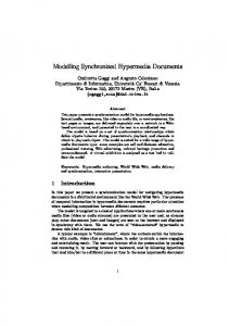
Figure 1. access, edge, and core routers
4.2
Resource management
video). An example application could be the use of a haptic As described in section 2 a management entity is required to administrate the resources of th device for aancritical over a proposed network.within the Differentiated Services work. We adopt approachoperation that was originally
work. There, a so called Bandwidth Broker [Nichols1997] is a domain-wide entity that exclu allocates bandwidth to requesting nodes.
2
1
ER
Approach
In SANDY, we introduce a Resource Manager (RM). The RM is responsible for several tas deal with the allocation of the network resources to users of its domain. There is exactly on per domain. Logically, the resource manager is located in the management plane of a network
The indeterministic nature of network delays is to a large degree determined by the stochastic queueing delays. Propagation Endand usertransmission interface When an end-system to use the SA service classare it has to issu delays (assumingwants a maximum packet size) quest. This request is sent to the RM. If the request can be accommodated, the RM enables t IP cores typically heavily overproviage deterministic. of this service forToday’s that particular user.are This step typically involves the reconfiguration sioned and queueing delaysthe areRM insignificant. Access/ rejection networks corresponding edge routers. Finally, signals the acceptance of the request user.are characterized by low to medium bandwidth links and the Policy Control The first step in deciding a request accepted is performed by the concentrator functionality. Whenwhether several flows isare multiplexed Control module which checks whether the user has the permission to use the SA service. on a medium bandwidth link, queueing delays can quickly beAdmission Policy Control fails,athe request islink passed to the10Admission C come Control high. As Unless an example, consider 2 Mbit/s where (AC) module. On the basis of the knowledge about ongoing reservations, AC tries to com flows are multiplexed. Even if it is assumed that each flow feasible schedule which includes the new request. The AC module is at thehas heart of the SA never more than 1 packet (of, say, 10000that bit)will at the concentrator, approach. Here, the resource allocation algorithms be developed within SANDY a plemented. the worst case delay is already 50 ms for that hop. It is obvious Inter-domain interface If a request isdelay for a communication path become that traverses that a worst case end-to-end bound can soon toomultiple do the RMs of the various domains have to communicate with each other to decide whether a r high for many real-time applications. can be accepted. An RM must therefore be equipped with an inter-domain interface to enab Taking into account the different characteristics of the netcommunication. work regions we employ specific strategies to construct the SA 4.3service Coreclass. network The main focus is on the access networks because Today's core are characterized by highunpredictability bandwidth links that arehave utilized to a sm theyIPare i) networks the primary source of delay and tent only. Typically the average load is in the range of 10-30%. If a backbone link utilizati ii) the largest potential for delay reduction. ceeds 50%, providers usually add more bandwidth. The network is logically divided into access and core region. As an example for such an overprovisioned backbone we refer to data [Sprint2004] publish As one shown figure 1 an access router2 shows (AR) the resides in the access Sprint, of theinlargest ISPs in the US. Table link utilization (averaged over 1s network and connects (a) local network(s) with a domain’s edge router (ER) which has the connection to the core router(s) (CR) of the network. For the core network it is assumed that SA traffic is handled in a separate traffic class that is granted high priority access to the link. Admission to this service is limited. These conditions provide for very little queueing delay. To make it a deterministic component it is proposed to compute a worst case queueing In the following, we describe the tasks the RM has to accomplish:
Given the networking demand of many embedded systems (often operating under real-time constraints) and the fact that the Internet Protocol IP [6] is settling as the standard networking layer, we believe there is an application for coupling local real-time networks over an IP network while still providing deterministic guarantees. In this paper we present an idea for realizing such a service in an environment where the local realtime networks are available (e.g. Profiline, Powerlink, etc). It is not the goal to use the service to ”make the whole Internet real-time”. The objective is to create a class that provides - in this order - 1) a deterministic upper bound on delay and delay jitter and 2) a low delay and jitter. It must be based on standard IP without any modification and it must be possible to forward standard best effort traffic in addition to and without degrading the performance of the real-time traffic. The new approach taken is to investigate the concept of synchronized transmission schedules at the IP layer. Transmission schedules are computed for the delay critical parts of a path such that a conflict free flow of packets is established in these regions. For easier reference, the envisaged service class is referred to as SA service (Synchronized Access) below. Applications relevant for such a service class have very stringent requirements on delay, jitter, and loss that can not be delivered by stochastic QoS approaches typically employed to support multimedia applications (voice, ∗ This work is funded by the Austrian Federal Ministry for Transport, Innovation, and Technology under the FIT-IT contract FFG 807142
delay. Given the small delays, even a worst case computation of the delay should yield a sufficiently small value. It is expected that a more sophisticated and fine-grained delay computation would not result in a significantly smaller upper bound for the queueing delay. This issue is therefore not further considered for the moment. In order to reduce queueing delays in the access area of the network a time-triggered synchronization of traffic at the IP layer is proposed. The approach has several similiarties to a classical TDMA approach. Time is conceptually divided into time slots. A number of slots are logically combined to a frame. For a given set of requests a transmission schedule is computed. The schedule covers one complete frame and is always repeated with the beginning of the next frame. The schedule is computed such that no more than 1 packet per time slot has to be sent at a router’s output port. If such a schedule exists, a conflict free transmission of IP packets is guaranteed for that router. Packets will always find an empty queue at the router output port and will thus experience no queueing delay. This concept makes packet forwarding a deterministic task as competition for bandwidth is precluded. On the ingress side, the transmission schedule is computed for the link from the access to the edge router because this link is considered the bottleneck on the ingress side. Concerning the connection between the end-systems and the access router it is required that the local real-time network enables an end-system to deliver a packet at specified times. These times are allocated by a resource manager when a service request was accepted. To implement a synchronized transmission schedule the participating nodes must have synchronized clocks. We plan to follow an architecture that is similar to the hierarchical CesiumSpray approach [9]. Access routers are equipped with GPS clocks that are used to externally synchronize the (physically dispersed) nodes. Each of these nodes in turn distributes the highly accurate official time as a reference time into a local network to which it is attached.
2.1 Synchronization of ingress and egress Analogous to the ingress side, a conflict free transmission schedule is employed for the link from the egress edge router to the egress access router. This transmission schedule is synchronized to the ingress schedule as described in the following. Between the ingress access router and the egress edge router the worst case queueing delay through the core network is known. It is therefore known when packets are ready to be sent at the egress edge router. If these time slots are indeed allocated for that flow we call this a zero delay (ZD) allocation scheme. Packets that arrive early are buffered at the egress edge router. It must be guaranteed that early packets from one flow can not delay packets from other flows. If a ZD scheme is not feasible because the requested time slots are occupied it is possible to exploit the delay budget (if any) that is given as the user’s requested delay minus the worst case delay through the core network (minus processing and other known delay components). This budget can be used to increase the probability of admission. One possibility is to delay each packet of a flow by a constant number of slots at the egress router. We denote this scheme as
constant delay egress, short CDE. Another variant is to selectively allocate slots with a variable delay at the egress router (VDE). One can easily construct realistic request/release sequences where a new flow can only be admitted if this variable delay allocation scheme is used at the egress. Finally, the maximum utilization is reached if allocation delays are jointly exploited at the ingress and egress router (VD). The VDE and VD scheme can only be used with respect to the jitter constraint specified in the service request. If the transmission schedule on the ingress side is established independently of the egress side, the send times of packets at the egress ER are fixed (worst case delay through the core). There is thus no flexibility in trying to accommodate a new request. It can only be checked whether the request fits in or not. If, however, the schedule for the ingress AR and egress ER is searched for collaboratively, the resource utilization gets higher as the free time slots can be matched to one another. To do this, a merged frame is created by aligning the egress frame to the ingress frame (shift by worst case delay) and logically combining them: a slot in the merged frame is free if and only if it is free in the ingress and aligned egress frame at that position.
3
Probability of admission
In this section we derive the probability that a request can be accepted in the ZD scheme. The frame class FN,s is defined as the set of frames that have a length of N slots out of which s slots are free. The slot positions within a frame are numbered from 1 to N , a slot is either in state free or busy. The function S : {1, . . . , N } 7→ {free,busy} maps a slot position to its state. It is assumed that the probability that a slot is free is the same for all positions. Each frame ∈ FN,s has a distinct set of free slot positions. A set of indices AN,s,f = {p1 , . . . , pf }, pi ∈ {1, . . . , N }, pi < pi+1 is defined as an allocation for a frame ∈ FN,s if the following conditions are fulfilled: · pi+1 − pi = N/f , ∀ i ∈ {1, . . . , f − 1} and · S(p) = free , ∀ p ∈ A. A frame is said to contain an allocation A if S(p) = free , ∀p ∈ A.
3.1
Single frame
First we derive the probability that a request with frequency f can be accepted in a frame ∈ FN,s . The acceptance probability PA (N, s, f ) = X/Y where X equals the number of frames ∈ FN,s that contain at least one feasible allocation and Y equals the total number of frames ∈ FN,s which is given by (Ns ). Note that a frame can contain multiple allocations, e.g. a frame with all slots empty contains all feasible allocations. It must be ensured that no frame is counted more than once. The term X can be calculated by applying the Principle of Inclusion and Exclusion (PIE). Let n = N/f . We divide the N slots into f groups of n slots each. Each position p from an allocation A must be in a distinct group. There are n allocations. The number of � frames � ∈�FN,s that contain � exactly a allocations is n N − (a × f ) given by × . a s − (a × f )
1
ZD CDE VDE VD, b=5
0.8 probability
For each frame containing an allocation, the first slot of the allocation can be chosen in (na ) ways (the remaining f − 1 slots of the allocation are fixed by the first) and the remaining s − af −af free slots can be chosen in (Ns−af ) ways. As each allocation requires f slots, the maximum number of allocations that a frame can contain is m = b fs c. For simplicity, � � we define� � n N − (i × f ) g(i) = and h(i) = . i s − (i × f ) By application of PIE, the number of frames ∈ FN,s that contain at least one feasible allocation is thus given by:
0.6 0.4 0.2 0
X
0
= g(1)h(1) − g(2)h(2) . . . (−1)m+1 g(m)h(m) m X = (−1)i+1 g(i)h(i) i=1
In total, the probability that a request with frequency f can be accepted at a frame of length N with s slots free is given in equation 1. Pm (−1)i+1 g(i)h(i) PA (N, s, f ) = i=1 (1) (Ns )
3.2
Zero Delay
It is assumed here for simplicity that both frames have the same length N and the same number of free slots s. In each frame, the free slots are assumed to be at random positions. The creation of the merged frame as described in section 2.1 results in a new frame ∈ {FN,s∗ }. The number of free slots s∗ in the merged frame depends on the positions of the free slots in the original frames. Clearly, max(0, 2s − N ) ≤ s∗ ≤ s. The probability PM that the merged frame contains exactly s∗ slots is given by: PM (N, s, s∗ ) =
−s (ss∗ )(Ns−s ∗) N (s )
(2)
As the frame classes FN,s∗ are a partition of the sample space the total probability theorem can be applied to compute the probability PZD that the request can be accepted under the ZD scheme: PZD (N, s, f ) =
s X
PM (N, s, s∗ )PA (N, s∗ , f )
(3)
s∗ =s∗ 0
where s∗0 = max(0, 2s − N ).
3.3
Constant Delay Egress
In the CDE scheme, a delay budget can be used to shift all packets of a flow at the egress by a constant amount of slots. To investigate whether a request can be accommodated in the CDE scheme a merged frame is created similar to the ZD case: the egress frame is aligned to the ingress frame by shifting the egress frame by the worst case delay plus an allocation budget b. Then the two frames are combined into one: a slot in the new frame is free if and only if it is free in the ingress and the aligned egress frame.
5
10
15 20 25 request frequency
30
35
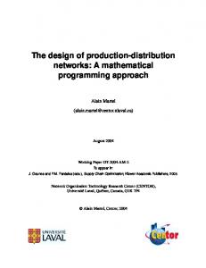
Figure 2. Admission probabilities for ZD, CDE, VDE, VD allocation schemes in a sample scenario (N = 32, s = 16, b = 5)
The admission probability for the CDE case, PCDE (N, s, f, b), can be derived directly from PZD (N, s, f ) which is abbreviated as PZD . The probability that a request can be accepted with a maximum budget of b equals 1 minus the probability that it can not be accepted with any budget of exactly b∗ , where b∗ ∈ {0, . . . , b}. It is thus given by: PCDE (N, s, f, b) = 1 − (1 − PZD )b+1
3.4
(4)
Variable Delay
We do not yet have analytical models for the variable delay schemes. The results shown below for the VD and VDE allocation scheme are achieved with a simulation model. This simulation tool is built on top of a Java implementation of the resource management layer (which is also used for the prototype described below). For the ZD and CDE case, the simulation results show a perfect match with the admission probabilities given by the models in equation 3 and 4, respectively. Figure 2 shows an exemplary result for a scenario where the frame length N = 32, number of free slots s = 16, and the maximum allocation delay budget b = 5. Note that the probabilities were only computed for specific frequencies (the points in the plot) and the connecting lines are just made to enable easier mapping of the points to their s value. As can be seen, the benefit of the CDE scheme over ZD is rather low in this scenario. The increase of admission probability of the VDE scheme compared to CDE is mostly for a request frequency of 4. In that case, CDE delivers a probability of 10.7%, VDE achieves 33.1%. For all other requested frequencies, there is virtually no difference between CDE and VDE. A major improvement can, however, be achieved by using the VD allocation scheme. In this scheme, allocation delays can be exploited at both the ingress and the egress frame. As can be seen clearly in figure 2, the admission probability is drastically increased compared to all other allocation algorithms although the delay budget b is only 5 slots. In real-world scenarions,
Figure 3. Prototype the budget can be expected to have significantly higher values leading to a higher admission probability.
4
Prototype
We are currently in the process of setting up a prototype to study the approach outlined above practically. The prototype is a laboratory testbed as shown in figure 3. All network nodes are standard PCs running Linux 2.6.12 with the adeos patch and RTAI 3.2 [7]. There are 3 local realtime networks (RL1, RL2, RL3) that are each connected to an access router denoted as SA router. The real-time LANs are realized by employing version 0.8.3 of the RTNET [3] stack provided by the University of Hannover. Each node is additionally connected to another network show as thin lines. This LAN is used for configuration, reservation signalling and traffic measurements. The basic scenario is that real-time applications that are located within RL1 / RL2 use the SA service to send traffic to real-time applications located in RL3. Additionally, best effort traffic is sent along the same routes. Before an application may utilize the SA service, it sends a reservation request to the resource manager (node labeled RM) which performs online admission control by searching for a feasible allocation using the algorithms described above. If the request can be accommodated, the two involved SA routers are updated with the new transmission schedule and the time when the application must start generating traffic is sent back as the reservation reply. The schedule is enforced by the SA routers. The timetriggered transmission process runs as a non real-time user process (with maximum priority). To make it usable in the testbed we enforce that the deviation between the sending time imposed by the transmission schedule and the real sending time never exceeds some preconfigured limit D (otherwise the scheduler quits and stops the test run) and account for D in the configuration of the worst case delay through the core. Time synchronization is provided by NTP [4]. All nodes are synchronized to a stratum 1 time server located on the host labeled RM. The clock precision among all nodes is within tens of microseconds. The demonstrator is a tele-haptic application operated over
the prototype testbed. A 3-DOF DELTA haptic device from Force Dimension is attached to node S1. A real-time process (RTAI task) reads the position vector of the haptic device with a fixed frequency and sends it via the SA service to node R1. At R1, a force vector is computed and sent back to the haptic device where the force is applied. The second type of applications are real-time traffic generators located at nodes S1, S2, S3, and S4. They also use the SA service to send data to traffic sinks located on node R1. Finally, non real-time applications located on the same nodes send best effort traffic along the same paths. First trials with measurements of one-way delay, traffic/timing behavior at the SA scheduler, and perceptual quality of the haptic device application, will be available at about the time of the conference.
5
Conclusion
This paper presents an approach for an IP service class that can be used to couple existing local real-time networks while keeping deterministic delay and jitter guarantees. The idea is to employ synchronized IP transmission schedules in the delay critical access areas of a network. The concept is illustrated and a model for the admission probability under a zero delay and constant delay egress allocation scheme is derived. This scheme is able to utilize only a very small portion of the available capacity. It is further shown that variable delay allocation schemes that utilize a delay budget to the amount allowed by the user request can significantly increase the admission probability which makes the general approach feasible. Finally, a prototype testbed is described. It will be used in the near future for a practical evaluation of the architecture.
References [1] J. C. Eidson, M. C. Fischer, and J. White. IEEE-1588 standard for a precision clock synchronization protocol for networked measurement and control systems. In 34 th Annual Precise Time and Time Interval (PTTI) Meeting, pages 243–254, 2002. [2] R. H¨oller, M. Horauer, G. Gridling, N. Ker¨o, U. Schmid, and K. Schossmaier. SynUTC - High Precision Time Synchronization over Ethernet Networks. In Proceedings of the 8th Workshop on Electronics for LHC Experiments, pages 428–432, Colmar, France, September 9-13 2002. [3] Jan Kiska, Bernardo Wagner, Yuchen Zhang, and Jan Broenink. RTnet - A Flexible Hard Real-Time Networking Framework. In 10th IEEE International Conference on Emerging Technologies and Factory Automation, September 2005. Catania, Italy. [4] David L. Mills. Internet time synchronization: The network time protocol. In Zhonghua Yang and T. Anthony Marsland (Eds.), Global States and Time in Distributed Systems. IEEE Computer Society Press, 1994. [5] Institute of Electrical and Electronics Engineers. IEEE Standard for Information Technology - Telecommunications and Information Exchange between Systems - Local and Metropolitan Area Networks - Specific Requirements - Part 3: Carrier Sense Multiple Access with Collision Detection (CSMA/CD) Access Method and Physical Layer Specifications, 2002. IEEE Std. 802.3-2002. [6] J. Postel. RFC 791: Internet Protocol, September 1981. [7] Real Time Application Interface (RTAI), website www.rtai.org. [8] Ulrich Schmid and Klaus Schossmaier. Interval-based clock synchronization. Journal of Real-Time Systems, 12(2):173–228, 1997. [9] P. Verissimo, L. Rodrigues, and A. Casimiro. CesiumSpray: a Precise and Accurate Global Clock Service for Large-scale System. Journal of Real-Time Systems, 12(3):241–294, May 1997.