Jun 2, 2010 - present TSync: a new multi-tier synchronization framework for 3DTI which can ... ticasting a global timestamp, or applying Precision Time. Protocol (PTP) .... To guarantee source reliability, we use TCP to send audio and video ...
TSync: A New Synchronization Framework for Multi-site 3D Tele-immersion Zixia Huang, Wanmin Wu, Klara Nahrstedt, Ahsan Arefin, Raoul Rivas Department of Computer Science University of Illinois at Urbana-Champaign {zhuang21, wwu23, klara, marefin2, trivas}@illinois.edu
ABSTRACT Synchronization is a challenge in the multi-site 3D teleimmersion (3DTI) because it is complicated by the coexistence of highly correlated heterogenous streams from multiple sources, and the need for multi-stream resynchronization when user views change. To address the problems, we present TSync: a new multi-tier synchronization framework for 3DTI which can effectively reduce the multi-stream sync skews. Our contributions are focusing on (1) the use of timed synchronization points for multi-stream synchronization; (2) Internet bandwidth estimation based on machine learning; (3) the cooperative frame rate allocation for correlated multi-streams and (4) the resynchronization protocol used when user views change. Experimental results show that TSync can successfully achieve the synchronization of multi-source heterogeneous streams in 3DTI under Internet dynamics.
Categories and Subject Descriptors H.5.1 [Multimedia Information Systems]: Video; C.2.1 [Network Architecture and Design]: Network communications
General Terms Design, Performance, Experimentation
Keywords 3D Tele-immersion, synchronization
1.
INTRODUCTION
3D tele-immersion (3DTI) is an application that creates a joint virtual space among geographically distributed users for realistic collaborations. Each 3DTI system usually includes three tiers. In the capturing tier, multiple 3D cameras and their processing computers produce multi-view 3D video streams in real time. Audio signals are sampled and encoded
Permission to make digital or hard copies of all or part of this work for personal or classroom use is granted without fee provided that copies are not made or distributed for profit or commercial advantage and that copies bear this notice and the full citation on the first page. To copy otherwise, to republish, to post on servers or to redistribute to lists, requires prior specific permission and/or a fee. NOSSDAV’10, June 2–4, 2010, Amsterdam, The Netherlands. Copyright 2010 ACM 978-1-4503-0043-8/10/06 ...$10.00.
to allow voice conversations. In the transmission tier, audio and multi-view 3D video streams are multiplexed at a local gateway and forwarded to the remote sites. In the rendering tier, both local and remote 3D video streams are aggregated and rendered into a joint virtual space at the display, while audios are mixed and played at the speakers. The synchronization of multiple sensory streams (e.g., audio and video) becomes a key challenge in 3DTI due to several characteristics. First, the audio streams have to be synchronized with multiple highly correlated video streams. The correlation results from the deployment of the 3D cameras in different positions to capture multiple views of the same scene. Second, because of 3DTI’s multi-tier architecture, a sync skew between any two streams in one tier can be propagated to the next tier. Third, the sync skew can be aggravated during its propagation. The sensory streams in 3DTI have heterogeneous Quality-of-Service (QoS) requirements, because different streams employ their own protocols and adaptation algorithms due to their different characteristics. This heterogeneity will inevitably result in different end-to-end latencies. Fourth, due to the multi-sensory nature of 3DTI systems, the sensory streams have to be carefully coordinated in all tiers in order to achieve proper synchronization. Fifth, Internet dynamics must be taken into account and timely frame rate allocation thus becomes a key issue. Sixth, user dynamics (e.g., change of user views [16]) should also be considered and resynchronization should be supported. Although there have been numerous studies on multimedia synchronization, their contributions in 3DTI are very limited. Early in 1990s, [3] classified different synchronization techniques used to control jitters. For audio-visual streaming, we can achieve lip synchronization by scheduling the rendering time [9, 10] or warping audio signals in time domain [4]. In distributed multimedia environments, we can synchronize multi-streams at the sender side by multicasting a global timestamp, or applying Precision Time Protocol (PTP) [1] at the renderer. However, none of these schemes consider the synchronization of multi-source highly correlated streams under their heterogenous QoS, nor do they discuss the concept of resynchronization under Internet and/or user dynamics. In this paper, we design TSync: a synchronization framework which can effectively minimize the multi-stream sync skews in all tiers. Unlike previous studies, our major contributions are as follows. (1) We introduce the concept of timed synchronization point and apply it in the 3DTI system to synchronize multi-streams with heterogenous QoS
C 1 Camera vs1 .. Sender . vsj C j Camera as Gateway Gsdr Asdr Audio
LAN
Internet
Display Receiver Gateway
Di1
Display
Gi
Dik
Audio
Ai
.. .
LAN
Sender Site Esdr
Receiver Site Ei
Figure 1: 3DTI architecture with 2 environments. and prevent sync skew propagations. (2) We impose machine learning on bandwidth estimation under Internet dynamics. (3) We develop the cooperative frame rate allocation scheme for correlated multi-streams to facilitate their coordinated delivery. (4) We propose a protocol for smooth resynchronization under user dynamics. We use the recommended in-sync region of a maximum 80-msec skew [13] as a design guideline. We consider the conversational scenario where end-to-end delays for both video and audio streams are important. The rest of the paper is organized as follows. Section 2 discusses the 3DTI system model. Section 3 presents a multi-tier overview of 3DTI synchronization issues and the TSync framework. Section 4 describes the design of TSync core components. Section 5 is the performance evaluations. Section 6 concludes the paper.
2.
The subscript i is omitted in the paper when �Ercv � = 1. The superscript j for the audio stream is omitted in the paper because �AS� = 1. †
1
vs vs2 vs3 Gsdr IB Gsdr OB
3
4
5
6
VIMS
VIMS
t
1
2
3
4
5
6
1
2
3
4
5
6
1
Gi IB
2
1
Gi OB Gi
2
Trigger
1
3
2
4
3
5
4
6
5
6
A-V Skew
k
Buffer 1
Ai
2
VIMS
3
4
5
6
VIMS
Figure 2: 3DTI Sync Issues. IB: incoming(receiving) buffer. OB: outgoing(sending) buffer. The second frame of vs2 is dropped by the Internet. Capturing-tier Synchronization Global Time Multicast C1
C2
C3
Timed Sync Point Cooperative Frame Rate Allocation Video Streaming
Asdr Audio Streaming
Rendering-tier Synchronization
Di1
Ai
Di2
A-V Sync Audio Buffering Audio Info Extraction
Timed Sync Point Traffic Measure & Bandwidth Est
Streaming Ctrl Feedback
3DTI SYSTEM MODEL
We classify 3DTI sites to be either sender or receiver. Let Esdr denote the set of sender sites, and Ercv be the set of receiver sites. Throughout the paper, we focus on the single sender (denoted as Esdr ) scenario, i.e., �Esdr � = 1. There can be multiple distributed receiver sites Ercv = {Ei }. As Fig. 1 shows, the sender site contains a set of source computing nodes Esdr = {C, Gsdr , Asdr } where C = {C j } are the cameras, Gsdr is the sender gateway, and Asdr is the audio microphone component. The i-th receiver site contains Ei = {Gi , Di , Ai }, where Gi is the receiver gateway, Di = {Dik } the displays or renderers, and Ai the audio speaker component. A path from the sender to a receiver may be routed through an overlay constituting several intermediate sites [15]. In terms of receivers, we consider three scenarios: (1) single-receiver, single-display: �Ercv � = 1, �D� = 1∗ ; (2) multi-receiver single-display: �Ercv � ≥ 2, �Di � = 1 and (3) single-receiver, multi-display: �Ercv � = 1, �D� ≥ 2. Due to the space limit, we will leave our multi-receiver multi-display scenario (ViewCast [15]: �Ercv � ≥ 2, �Di � ≥ 2). The data streams from site Esdr are denoted as S = {AS, VS, . . .}, where AS = {asj } is the set of audio streams, and VS = {vsj } is the set of video streams. We assume the sender site produces one audio stream, i.e., �AS� = 1. Each stream s (either as or vsj )† consists of frames {f1 , f2 , . . .}. The set of video frames that is taken from different cameras at the same time at one site are called a macroframe. The frame rate of s can be different at its source C j or Asdr , the local gateway Gsdr , the receiver gateway Gi , and the display Dik , for which the frame rates are denoted as F Rsp , F Rsgs , F Rsgr , F Rsd , respectively. We define the concept of a display dominant stream (DDS) ddski to be the most important video stream among the correlated multi-source stream bundle for Dik . The selection ∗
Asdr
Transmission-tier Synchronization
Figure 3: TSync overview. of DDS for each display is based on maximizing contribut� vsj (orientation of ing factor (CF) which is determined by O � k (orientation of the user view for camera for vsj ) and O ui � vsj · O � k [16]. We denote a set of DDS for all Dik ): CF = O ui
displays at a receiver site Ei as DDS i = {dds1i , dds2i , . . .}. Because it is impossible to synchronize the audio stream with multiple correlated video streams, we also define the receiver site dominant stream (RDS) rdsi to be the most important stream among DDS i at the receiver site Ei and it is the actual video stream that is used to be synchronized against the audio. The RDS rdsi is selected from DDS i ��D � � � such that rdsi = arg maxs { k=1i O s · Ouk , s ∈ DDS i }. i Note that we limit both the number of DDS for each display and the number of RDS for each receiver site to be one. Other video streams in the multi-source correlated bundle that are neither RDS nor DDS are called non-dominant streams (NDS), and are denoted as a set N DS i .
3. A MULTI-TIER OVERVIEW OF TSYNC We add the audio components to current 3DTI implementation [15]. The synchronization issues are illustrated in Fig. 2. We provide an overview on how these issues are addressed in TSync framework (Fig. 3). • Capturing-tier Each 3DTI site should enforce the synchronous capturing of correlated multi-source streams. In our previous work [15] a video trigger has been adopted at each sender site to allow synchronous capturing of images (Fig. 2). Basically the trigger sends a hardware “grab” signal to all 3D cameras at its site through wired cords when they become ready to capture the next frame. When the signals are sent in TSync, we also send a small soft packet piggybacking a global timestamp
Gsdr IB Gsdr OB
1
Barrier
Barrier
2
1
Gi IB Gi OB
2
t
1
Barrier
1
Barrier
1
Replicated
Figure 4: Timed synchronization points (Barrier) in 3DTI. IB: incoming buffer; OB: outgoing buffer.
Tg to all cameras as well as the audio microphone component in order to facilitate audio-visual synchronization in the rendering tier. Because audio frames are transmitted more often than video frames, we also maintain a local timestamp in the audio stream for intra-stream synchronization at the audio speaker component at the receiver site. To guarantee source reliability, we use TCP to send audio and video frames from the source cameras and audio speaker component to the sender gateway. Its congestion control and retransmission mechanism will cause asynchronous packet arrivals. We define video intra-macroframe skew (VIMS) as the arrival time skew between the first and the last frame belonging to the same macroframe (Fig. 2). To synchronize the video macroframe at the sender gateway, we apply the timed synchronization point in TSync which, due to the 3DTI real-time characteristics, has a bounded time waiting for the arrival of a video macroframe before it is placed in the outgoing (sending) buffer at the sender gateway (Section 4.1). • Transmission-tier Traffic stream differentiation affects the multi-stream synchronization. Between the sender and receiver gateways in 3DTI, we use UDP for audio transmissions to guarantee a constant frame period, while video utilizes DCCP [8] to adapt to Internet congestions. When the multi-stream data rate exceeds the network bandwidth capacity, both video and audio frames can be dropped over the Internet, and the DCCP sending rate will be reduced in response to the congestion. These problems will create huge synchronization issues at the receiver gateway. One solution is to estimate the network bandwidth and allocate the frame rates for each stream in different scenarios. Redundant frames can be discarded at the sender gateway. However this solution is complicated by the Internet dynamics, the correlated multi-stream coordination, and the diverse multi-site topology. We will address the issues in Section 4.2 and 4.3. To avoid Internet congestions and losses at the sender side, we apply the time spacing technique to video streaming in TSync. We use a simple strategy that two consecutive frames within a synchronized video macroframe are sent in a separation of 5 msec and two consecutive fragmented packets within a video frame in a separation of 10 μsec. The time spacing and the Internet dynamics will introduce jitters (and thus VIMS variations in Fig. 2) at the receiver site. In order to resynchronize all video streams so that a complete macroframe can be sent to the renderer, we need to apply the timed synchronization point at the receiver gateway as well (Section 4.1). • Rendering-tier In TSync, we use a simplified version of our previous study [11] to allow lip synchronization. The audio buffering time is the sum of average 3D video rendering time (15 msec
on average per macroframe including 4 video streams [14]), and an empirical 80th percentile audio-visual arrival skew (the arrival time skew between the last frame of a video macroframe and the audio frame with the same global timestamp Tg ) in the previous 2 seconds at the receiver gateway. We assume the audio playing time is negligible. Note that the audio buffer should only be adapted during silence periods and a minimal audio buffering time of 60 msec should be guaranteed [6]. We also propose a resynchronization protocol for the smooth view change in Section 4.4.
4. TSYNC CORE DESIGN 4.1 Timed Synchronization Points Fig. 4 shows the deployment of timed synchronization points at both sender and receiver gateways to deal with the asynchronous multi-stream arrivals. This can be achieved by the timed barrier implementation. Only video streams are affected by the barrier in the current design. The timed barrier will immediately be released if a video macroframe is completely received within the bounded time. Otherwise it needs to wait until the bounded time expires before it releases the macroframe. If a frame is missing or incomplete at the release, the barrier needs to replicate the previous correctly received frame belonging to the same video stream. The amount of waiting time depends on where the barrier is located. At the sender gateway, an incomplete video macroframe will not be placed in the outgoing buffer until the gateway starts to receive the next macroframe from the source cameras. At the receiver gateway, the latest barrier release time is either when it starts to receive the next macroframe from the sender gateway, or the 60 msec behind the audio playing time with the same timestamp Tg , whichever is earlier. We use 60 msec because the recommended in-sync region is 80 msec and we leave 20 msec for video rendering time [14]. If the multi-streams are relayed by an intermediate site, a barrier is deployed at this site to synchronize a video macroframe before it is released and forwarded to other sites. The waiting time incurred on the barrier from the last release is T D + ΔT in msec, where T D is the duration between the last release and the arrival of the first frame belonging to the new macroframe, and ΔT is the expected VIMS. Note that a longer ΔT will accommodate larger VIMS, reduce the missing frame rate and hence improve 3D video quality. However, ΔT is directly related to the end-to-end latency, so a longer ΔT will degrade the interactivity of 3DTI systems. We should balance a tradeoff between the video quality and the interactivity in deciding ΔT . In Section 5, we set ΔT = 50msec so that the one-way end-to-end latency can be bounded by 400 msec recommended in ITU G.114 [7] for up to three intermediate sites [15].
4.2 Bandwidth Estimation based on Machine Learning A real-time 3DTI system requires huge amounts of bandwidth for its multi-stream transmission. Hence it is important to determine the network’s effective bandwidth EB, the maximum bandwidth allowed for 3DTI streaming such that no congestions will be incurred (overall packet loss rate (LR) for the multi-stream bundle is less than 5% in this paper). However EB is unlikely to be measured at run time using existing tools such as [5], because the traffic flows used for
bandwidth measurement can affect the throughput of the 3DTI multi-streams. Simple techniques like measuring the DCCP throughput at the receiver gateway are good only when EB is less than or equal to the multi-stream bandwidth requirement. EB can be under-estimated when it far exceeds the multi-stream bit rate. In addition, the measured DCCP throughput at the receiver gateway may not automatically tell if EB increases due to a congestion reduction, and this drawback will prevent future adaptations. Our approach is to give a rough estimation of EB between the sender and receiver gateways at run time using the machine learning approach based on the eight traffic statistics: (1) audio jitter (>60 msec) percentage , (2) average video throughput, (3) average VIMS, (4) maximum VIMS, (5) average macroframe size (6) the macroframe size corresponding to the maximum VIMS, (7) overall LR and (8) number of video streams. We have noticed that the eight parameters will affect EB either through linear or non-linear relations, and we believe they are sufficient to model EB. We take the number of video streams into account because it will affect VIMS due to the time spacing. In order to find a mapping F between EB (called dependent variable, denoted as y) and the eight statistics (called independent variables, denoted in a vector expression � x with each statistic xi ), we use support vector regression (SVR) [12] for machine learning. The general idea of SVR is to find a linear hyperplane function F = w � ·� x + b such that the deviations of F(� x) from the target y are minimized. To solve nonlinear relations between � x and y, a mapping of � x → φ(� x) using a radial basis kernel function has to be applied. We use LIBSVM [2] to do the regression. We first need to build the regression model and establish a mapping between � x and y in the off-line training process. We take the following steps: Step 1: we throttle the target bandwidth capacity (i.e. EB or y) to be 10Mbps using tc software in Linux. We vary the transmission data rate of 3DTI video streams at the sender gateway, so that the resulting eight traffic statistics (� x) can exhibit variations. Step 2: we iterate step 1 by varying target bandwidth capacity from 10Mbps to 50Mbps (in a separation of 5Mbps), hence SVR can see a variety of situations. Based on � x and the corresponding y, LIBSVM will solve the optimal hyperplane parameters and the prediction mean squared error (MSE) σ 2 of the trained model. Given the trained regression model, we can now apply it at run time to estimate EB in TSync by inputing the eight independent variables to LIBSVM. Due to the Internet dynamics, we only use the average of the most recent 10-sec traffic information. In our experiment, we can achieve a prediction MSE σ 2 = 27.2 (σ = 5.2 Mbps). Of course, there may be unseen network conditions that can over-estimate EB (overall LR is larger than 5%), we record � x that predicts this EB. Every second we reduce the frame rate by one for each video stream, until the overall LR is within the 5% threshold. We compute the new incoming throughput at the receiver gateway and use it to replace EB. Along with all the off-line training data, the updated EB and the recorded � x can be used to retrain the regression model and improve the prediction accuracy.
4.3 Cooperative Frame Rate Allocation In [16], we adapt the bandwidth availability by the dynamic allocation of multi-stream frame sizes based on CF. However this method does not address the synchronization
issues and will create additional computational overhead. In TSync framework, we propose an alternative cooperative frame rate allocation scheme. Its main purpose is to allow the largest possible frame rate for the audio stream as, video RDS and DDS in the scheme to facilitate audio-visual synchronization and achieve good audio and 3D video quality. The allocation is based on the regression result EB. To determine the proper frame rate F Rs of a stream s (either as or vsj ) at a given EB, we need to estimate the future frame size F Ss (n), where n is the current frame index. This can be achieved by a linear predictor: F Ss (n + 1) = �L l=0 al × F Ss (n − l), where L is the predictor order and al (l = 0, 1, . . . , L) are the coefficients. In TSync these coefficients are computed using the Levinson-Durbin recursion approach based on the frame size of the first 50 consecutive frames of stream s received at the sender gateway from the source cameras and audio microphone component. We tested different order L, and found that any L ∈ [6 10] can achieve a prediction accuracy of 90% of samples within 5% deviation and 99% samples within 10% deviation. We simply choose L = 8 in TSync. Note that to make the computations consistent, in this section we represent EB in ’bits/sec’, F Rs in ’frames/sec’ and F Ss in ’bits’. We discuss our frame rate allocation scheme in the three scenarios mentioned in Section 2. In all scenarios, the as should synchronize to RDS. In the first two scenarios, because each receiver site has only one display, RDS of the receiver site is the same as the DDS of its display. In scenario 3, RDS should be determined among all DDS at the receiver site based on the strategy mentioned in Section 2. • Scenario 1: Single-receiver Single-display The sender gateway determines F Rs for each stream s based on the RDS information and regression estimation EB. We simply prescribe that all other non-dominant video streams share the same frame rate at the receiver gateway and the renderer. We denote rds as the receiver site RDS (same as the DDS in this scenario), and EBNDS = EB − p p (F Rrds × F Srds + F Ras × F Sas ). If EBNDS ≥ 0, F Rsgs can be determined ⎧ by: p s = as F Ras ⎨ p gs F� Rrds s = rds F Rs = (1) ⎩ EB NDS /( s∈N DS F Ss ) s ∈ N DS If EBNDS < 0, there is not enough bandwidth for rds. Let p EBrds = EB − F Ras × F Sas , F Rsgs is computed as: � p F Ras s = as EBrds /(F Srds ) s = rds (2) F Rsgs = 0 otherwise • Scenario 2: Multi-receiver Single-display In this scenario, �Ercv � = M and �Di � = 1. Each multistream bundle destined to one receiver behaves as background traffic of other receivers, so we estimate the bandwidth and allocate the frame rate for each receiver individually. We use Eq. 1 and 2 to compute F Rsgs for each stream s targeted to receiver site Ei based on its rdsi and EBi . M regression estimations should be conducted in this scenario. The audio stream as only synchronizes to rdsi at each receiver site Ei , and there is no guarantee for inter-site synchronous rendering among multiple receiver sites. • Scenario 3: Single-receiver Multi-display In this scenario, �Ercv � = 1 and �D� = M . We select rds among DDS = {dds1 , . . . ddsM }. EB is estimated
x 10
4
0.3
150
1
vs 6
2
vs
vs3 4
4
vs
Repliation Rate
8
100
50
2 0 0
100 200 300 Video Macroframe index
0 0
0.2 0.15 0.1 0.05
100 200 300 Video Macroframe index
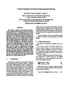
Figure 5: Video frame variations of the 4 video streams and corresponding VIMS at the sender gateway.
between the sender and the receiver gateways. If EB ≤ p p × F Sas + F Rrds × F Srds ), we use a similar approach (F Ras as in Eq. 2 to determine the frame rate of rds. Otherp p × F Sas + F Rrds × wise we � let EBNDS = EB − (F Ras p F Srds + s∈DDS,s�=rds F Rs × F Ss ). We prescribe that all s ∈ DDS, s �= rds share the same F Rsgs in this paper. If gs EBNDS ≥ 0, we compute F Rs∈N DS similar to Eq. 1. If EBNDS < 0, two methods can be applied. gs • Method 1: we can reduce the uniform F Rs∈DDS,s� =rds to: p p EB − (F Ras × F Sas + F Rrds × F Srds ) � (3) s∈DDS,s�=rds F Ss However this method may degrade the user experiences if the video frame rate is below a threshold F Rth , the minimal frame rate that can provide acceptable rendering quality (e.g. 5 frames/s). Hence we propose the second method. • Method 2: we can reduce the number of DDS(excluding rds) until EBNDS ≥ 0. This can be achieved by iterations. In each iteration, we remove the ddsj whose F S is the largest among all DDS(excluding rds). We replace the ddsj with ddsk from the remaining DDS(including rds) such that the resulting CF can be maximized. For example, in a M = 3 scenario, we substitute dds1 (the rds) for dds2 because � dds1 · O � u2 > O � dds3 · F Sdds2 has the largest frame size and O � u2 . O
4.4 Resynchronization Protocol When a user requests a view change at a display, the DDS may change to another video stream which either may not be available or does not have enough frames to render due to frame rate allocation. Hence a resynchronization framework should be developed to allow smooth view changes for all the three scenarios. Suppose the original DDS is vsk , the details of the protocol are illustrated as follows. • Step 1: upon the request of a view change, the new DS (vsj ) is determined and F Rsgs of each stream s is updated based on the allocation scheme in Section 4.3. gr • Step 2: if F Rvs j is above the threshold F Rth , the renderer immediately changes DDS to vsj . Otherwise it determines the video stream set Srvs that satisfies: ∀ s in Srvs , F Rsgr ≥ F Rth . If Srvs is not empty, during the changing period we temporarily use the stream in Srvs with the largest resulting CF (to the new view). Otherwise, we simply keep the origigr nal stream vsk for DDS until F Rvs j is greater than F Rth .
5.
#Video Streams = 1 #Video Streams = 2 #Video Streams = 3 #Video Streams = 4
0.25
VIMS (msec)
Frame size (bytes)
10
EXPERIMENT RESULTS
We evaluate our synchronization scheme in the 3DTI testbed. One microphone and four 3D cameras are used at the sender site. To make our results repeatable, we record at the sender gateway the size and the arrival time of each video
0
10
30 Bandwidth (Mbps)
50
Figure 6: Replication rate at the renderer. Replication rate for 4 streams at 10Mbps is more than 50%, and is not shown completely in the figure.
and audio streams. We use tc software in Linux to simulate real Internet environment. The delay, jitter and loss data are collected from PlanetLab sites in the US. • Sender Gateway VIMS Fig. 5 shows the frame sizes of the four streams from the source cameras, and the corresponding VIMS at the sender gateway. We find that VIMS is related to frame size diversity within each macroframe, and can be larger than 100 msec. This is due to the fact that larger frames usually require more computation time at the cameras. The bandwidth capacity at the sender gateway and the gateway’s thread scheduling may also affect VIMS. These results confirm that capturing-tier synchronization is necessary. • Renderer Video Replication Rate We evaluate our regression estimation and cooperative adaptation scheme under different bandwidth configurations. We define the replication rate as the percentage of video frames that need to be replicated due to the missing or incomplete frames at the receiver gateway. We vary the bandwidth (between the sender and the receiver gateway) at 10, 30, 50 Mbps in scenario 1 respectively with no intermediate site, and the results (Fig. 6) show that the replication rate is less than 3% for four video streams with 50Mbps bandwidth, and a reasonable 15% with 30Mbps bandwidth. 10Mbps bandwidth is not sufficient to support concurrent 4 streams, and will lead to a replication rate of more than 50%. In order to achieve similar replication rates in scenario 2, the bandwidth capacity at the sender gateway should increase in proportion to �Ercv �. • Receiver VIMS and Audio-Visual Skew In this section, we use 50Mbps upload/download bandwidth for all sites in our measurement. Fig. 7(a) presents the sizes of each video macroframe constituting 2 or 4 streams, and Fig. 7(b) shows the corresponding VIMS at the receiver gateway in scenario 1. We notice that VIMS is affected by the video macroframe size. The majority of VIMS is below 25 msec for 2 streams and 80 msec for 4 streams. We present the percentile of the aggregate barrier latency (the latency incurred on barriers at all intermediate sites and the receiver gateway) in Fig. 7(c) using 4 video streams. We compare two cases: (1) no intermediate sites (2) two intermediate sites between the sender and receiver gateways. The results show that only 50% of VIMS are below 150 msec for the second case, and the highest VIMS can be as large as 185 msec. The numbers will definitely degrade the 3DTI interactivity. Unlike the video streams, the audio stream will not be affected by the barrier in the current 3DTI implementation. Fig. 8(a) presents the audio-visual arrival skew at the re-
5
x 10
100 #VS=2 #VS=4
1.5 1 0.5
1
#VS=2 #VS=4
80 60 40 20
0 0
100 200 300 Video Macroframe Index
0 0
# IS=0 # IS=2
0.8 Percentile
2
VIMS (msec)
Video Macroframe Size (bytes)
2.5
0.6 0.4 0.2
100 200 300 Video Macroframe Index
0 0
50 100 150 VS Sync Skew (msec)
200
Figure 7: (a)Left: video macroframe size; (b)Middle: VIMS at the receiver gateway; (c)Right: Percentile of aggregate barrier latency for 4 video streams for 0 and 2 intermediate sites (IS). VS: video stream.
150 100 50 0 0
100 200 300 Video Macroframe Index
200
150
150 100 Ideal Real
50 0 0
100 200 300 Video Macroframe Index
Audio−Visual Lip Sync Skew (msec)
#VS=2 #VS=4
200
Adjusted Audio buffer size (msec)
Audio−Visual Arrival Skew (msec)
250
Ideal Real
100
50
0 0
100 200 300 Video Macroframe Index
Figure 8: (a)Left: audio-video frame arrival skew; (b)Middle: audio buffer adjustment for 4 VS. Ideal: all silences, real: talkspurts and silences; (c)Right: Resulting audio-visual sync skew for 4 VS. VS: video stream. ceiver gateway for scenario 1. It shows that there is an approximate average of 130-msec skew for 4 video streams and 30-msec for 2 streams. So without audio buffer adjustment at the renderer, the 130-msec number already exceeds the 80-msec audio-visual sync threshold guideline. Fig. 8(b) shows the adjusted audio buffer size in 4 video stream scenario. The ideal case is that the audio source remains silent, hence audio buffer can be adapted at any time. The real situation is that silences only happen at certain time, so audio buffer size will remain unchanged during talk-spurts (video macroframe 1-35, 95-179, 263-300 in Fig. 8(b)). Fig. 8(c) demonstrates the resulting audio-visual lip sync skew in both cases. More than 95% of the sync skews are within 80-msec threshold. Due to the space limit, we will not present scenario 2 and 3 which exhibit similar TSync effectiveness.
6.
CONCLUSIONS
We present TSync, the multi-tier audio-visual synchronization scheme for the 3DTI system. Our scheme can actually be extended to any correlated multi-source distributed multimedia environment with diverse QoS. Experiment results show that with TSync the audio-visual sync skew at the renderer can satisfy the 80-msec threshold. We would like to acknowledge the support by NSF CNS 0720702 and 0834480, by UPCRC grant from Intel and Microsoft, and by Grainger Grant.
7.
REFERENCES
[1] IEEE 1588 standard: Precise time synchronization as the basis for real time applications in automation, 2008. [2] C. C. Chang and C. J. Lin. LIBSVM: A library for Support Vector Machines. [3] L. Ehley, B. Furth, and M. Ilyas. Evaluation of multimedia synchronization techniques. In Proceedings of IEEE International Conference on Multimedia Computing and Systems, pages 110–119, May 1994.
[4] S. Goldenstein. Time warping of audio signals. In Proceedings of IEEE Conference on Computer Graphics, pages 52–57, 1999. [5] N. Hu and P. Steenkiste. Evaluation and characterization of available bandwidth probing techniques. IEEE JSAC Special Issue, Aug. 2003. [6] Z. X. Huang, B. Sat, and B. W. Wah. Automated learning of play-out scheduling algorithms for improving the perceptual conversational quality in multi-party VoIP. In Proc. IEEE ICME, pages 493–496, July 2008. [7] ITU-G.114. One-way transmission time, 2003. [8] E. Kohler, M. Handley, and S. Floyd. Datagram Congestion Control Protocol (DCCP), Mar. 2006. [9] T. Little. A framework for synchronous delivery of time-dependent multimedia data. Multimedia Systems, 1(2):87–94, 1993. [10] H. Liu and M. Zarki. An adaptive delay and synchronization control scheme for Wi-Fi based audio/video conferencing. Springer Wireless Networks, 12(4):511–522, July 2006. [11] K. Nahrstedt and L. Qiao. Stability and adaptation control for lip synchronization skews. Tchnical report, University of Illinois, USA, 1997. [12] A. Smola and B. Scholkopf. A tutorial on support vector regression. Technical report, Statistics and Computing, 2003. [13] R. Steinmetz. Human perception of jitter and media synchronation. IEEE Journal on Selected Areas in Communications, 14(1):61–72, 1996. [14] W. Wu, Z. Yang, and K. Nahrstedt. Implementing a distributed 3D tele-immersive system. In Proceedings of IEEE International Symposium on Multimedia, 2008. [15] Z. Yang, W. Wu, K. Nahrstedt, G. Kurillo, and R. Bajcsy. Enabling multi-party 3d tele-immersive environments with viewcast. ACM Transactions on Multimedia Computing, Communications, and Applications, 2010. [16] Z. Yang, B. Yu, K. Nahrstedt, and R. Bajscy. A multi-stream adaptation framework for bandwidth management in 3D tele-immersion. In NOSSDAV, 2006.