IEEE JOURNAL OF SELECTED TOPICS IN QUANTUM ELECTRONICS, VOL. 17, NO. 6, NOVEMBER/DECEMBER 2011
1505
Tunable Distributed Amplification (TDA-) DFB Laser with Asymmetric Structure Nobuhiro Nunoya, Member, IEEE, Hiroyuki Ishii, Member, IEEE, Yoshihiro Kawaguchi, Ryuzo Iga, Tomonari Sato, Naoki Fujiwara, Member, IEEE, and Hiromi Oohashi, Member, IEEE
Abstract—The wavelengths of tunable distributed amplification (TDA) distributed feedback (DFB) lasers consisting of multiple units including an active region and a tuning region can be changed without mode hopping. To expand the tuning range of TDA-DFB lasers, an asymmetric periodic structure is proposed where the units in the cavity have different lengths. It is shown theoretically that the asymmetric periodic structure is effective for expanding the mode-hop-free tuning range. In addition, a tunable laser array was fabricated consisting of six TDA-DFB lasers with an asymmetric periodic structure. A total wavelength tuning range of 44 nm was successfully obtained by expanding the tuning range of each laser, which corresponded to 110 channels with a 50-GHz grid. Moreover, the channel switching speed was investigated in relation to thermal drift. A switching time of less than 40 μs with a frequency deviation of less than 1 GHz was achieved with a thermal drift suppression technique that used the tuning regions of non-lasing lasers as heaters for temperature compensation. Index Terms—Mode-hop-free tuning, thermal wavelength drift, tunable distributed amplification (TDA) distributed feedback (DFB) laser, tunable wavelength laser.
I. INTRODUCTION UNABLE wavelength lasers are used as light sources for wavelength division multiplexing (WDM) networks [1] because one tunable laser can provide multiple channels. In addition to wide band tuning and reliable operation, the lasers must be capable of high-speed wavelength tuning for future photonic networks based on WDM, such as wavelength routing systems. The lasing wavelength of a tunable laser depends on the refractive index of the waveguide forming the laser cavity. The refractive index of a semiconductor can be changed greatly by several methods, such as varying its temperature or injecting a current. We have already developed a tunable laser array (TLA) consisting of multiple distributed feedback (DFB) lasers with thermal control [2]. DFB lasers are widely used for optical fiber communication systems due to their stability and reliability. With DFB lasers, the carrier density is limited under lasing con-
T
Manuscript received November 30, 2010; revised February 7, 2011; accepted February 13, 2011. Date of publication April 15, 2011; date of current version December 7, 2011. N. Nunoya, H. Ishii, R. Iga, T. Sato, N. Fujiwara, and H. Oohashi are with NTT Photonics Laboratories, Nippon Telegraph and Telephone (NTT) Corporation, Kanagawa 243-0198, Japan (e-mail:
[email protected];
[email protected];
[email protected];
[email protected];
[email protected];
[email protected]). Y. Kawaguchi is currently with NTT Electronics (NEL) Corporation, Kanagawa 243-0198, Japan (e-mail:
[email protected]). Color versions of one or more of the figures in this paper are available online at http://ieeexplore.ieee.org. Digital Object Identifier 10.1109/JSTQE.2011.2123083
ditions and so the chip temperature has to be changed to tune the lasing wavelength. In general, changing the temperature of a semiconductor takes longer than current injection. On the other hand, carrier-induced effects caused by current injection, such as the carrier plasma effect and the band filling effect, provide a large and fast refractive index change. Therefore, many types of lasers have been reported whose wavelengths are tuned by current injection. Distributed Bragg reflector (DBR) lasers [3], [4] are widely known as tunable lasers that employ current tuning, where the Bragg wavelength is controlled with the carrier density in the DBR. Sampled grating (SG-) [5] or superstructure grating (SSG-) [6] DBR lasers are special structures designed to expand the tuning range by using multireflection peaks, namely the vernier effect. Vertical grating-assisted codirectional coupler lasers with a superstructure grating (GCSR) DBR [7], modulated-grating Y-branch lasers [8], and digital supermode (DS-) DBR lasers [9] have also developed for wideband tuning. For most DBR-type tunable lasers, both the reflected wavelength and the phase must be controlled to avoid mode hopping. Therefore, current injection-type tunable wavelength lasers without mode hopping have also been developed. These include tunable twin guide lasers [10], short cavity DBR lasers [11], and phase-controlled short cavity DFB lasers [12]. Tunable interdigital electrode (TIE-) DBR lasers [13] followed by tunable distributed amplification (TDA-) DFB lasers [14] provide an innovative method for synchronizing both the Bragg wavelength (reflection peak) shift and the longitudinal mode (phase) shift, thus making continuous tuning possible. Furthermore, TDA-DFB lasers can be tuned by a single tuning electrode, which provides easy and reliable control of the lasing wavelength. In addition, these lasers can be easily integrated with other optical components such as semiconductor amplifiers (SOA) and modulators [15]–[17]. In this paper, a cavity with an asymmetric periodic unit structure was studied theoretically and experimentally, and it was used to expand the tuning range with a good single-mode property. As a result, we achieved 110-channel operation with a 50-GHz grid for a TDA-DFB laser array consisting of six lasers (LDs), a multimode-interferometer (MMI) coupler, and an SOA. We also measured the channel switching speed with respect to the thermal frequency drift. Furthermore, we applied the thermal drift suppression technique to cases where there were channels in the same LDs and in different LDs. II. PRINCIPLE OF AN ASYMMETRIC TDA-DFB LASER Fig. 1 shows the structure of the asymmetric TDA-DFB laser, where active layers and tuning layers are distributed alternately
1077-260X/$26.00 © 2011 IEEE
1506
IEEE JOURNAL OF SELECTED TOPICS IN QUANTUM ELECTRONICS, VOL. 17, NO. 6, NOVEMBER/DECEMBER 2011
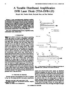
Fig. 1. Cross-sectional schematic view of the asymmetric TDA-DFB laser. It has two sections with different unit lengths Li consisting of one active layer and one tuning layer on either side of a λ/4 shift.
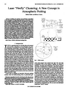
and periodically. Both layers have a diffraction grating and there is a λ/4 phase shift at the center of the cavity for single-mode operation. The unit, which consists of one active layer and one tuning layer, has a length of Li (i; section number). The ratio of the active region to the tuning region (Lai :Lti ) is constant for every unit so that the Bragg wavelength shift and the longitudinal mode shift are synchronized automatically during tuning. Mode hopping occurs due to the difference between the Bragg wavelength shift and the longitudinal mode shift. However, both shifts are always the same in TDA-DFB lasers. Since the upper electrodes in each region are connected to each other, just one tuning current can change the lasing wavelength. The injection of a current into the tuning regions decreases the refractive index. Therefore, the lasing wavelength of the TDA-DFB laser moves to the shorter wavelength side continuously without mode hopping. However, as the difference between the refractive indexes of the active and tuning regions becomes large, the grating becomes similar to a SG, and subreflection peaks are generated on both sides of the main reflection peak with a period that is inversely proportional to the unit length. Consequently, the tuning range with a single mode is limited by submode generation. To expand the potential tuning range by suppressing the side modes during tuning, we developed the asymmetric TDA-DFB laser. The unit lengths of section 1 (L1 ) and section 2 (L2 ) for each side of the λ/4 shift are different. Fig. 2 illustrates the operating principle, and shows the schematic reflection spectra of both sections 1 and 2, the longitudinal modes and the lasing spectrum. As shown in Fig. 2(a), before tuning, lasing occurs at the wavelength of the reflection peak that overlaps one of the longitudinal modes. Fig. 2(b) shows that increasing the tuning current synchronously shifts both the reflection peak and the longitudinal mode to a shorter wavelength. Fig. 2(c) reveals that a further increase in the tuning current generates subreflection peaks on both sides of the main mode. This is because of the periodic arrangement of the tuning regions, which is like a SG. The asymmetric periodic structure of our TDA-DFB laser prevents the generation of supermodes. Sections 1 and 2 have different unit lengths. The reflection peak of Section 1 does not match that of Section 2 because the mode spacing is inversely proportional to the unit length. Therefore, the lasing wavelength moves continuously without mode hopping. Fig. 3 shows the calculated results of the threshold gain of the main mode gth and the threshold gain difference between the main mode and the next mode divided by the threshold gain
Fig. 2. Illustrations to explain the supermode suppression in the asymmetric TDA-DFB laser structure. Reflection spectra, longitudinal modes, and lasing spectra are shown for three cases: (a) before tuning, (b) tuning current increased, and (c) tuning current further increased.
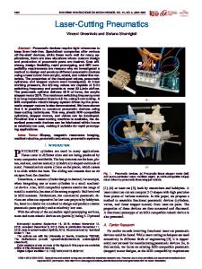
Fig. 3. Calculated results of the threshold gain of the main mode and the threshold gain difference between the main and second modes for both the symmetric and asymmetric structures while changing the equivalent refractive index difference between the active and tuning regions.
of the main mode (Δgth /gth ) as a function of the equivalent refractive index difference Δn between the active and tuning regions. The main mode means the lasing mode before tuning. The next mode means the mode with the lowest threshold gain except for the main mode. All the calculations were performed for both the symmetric structure and the asymmetric structure. In Fig. 3, the results for the symmetric and asymmetric
NUNOYA et al.: TUNABLE DISTRIBUTED AMPLIFICATION (TDA-) DFB LASER
structures are indicated by triangles and circles, respectively. The gth and Δgth /gth values are represented by unfilled and filled symbols, respectively. These calculations were performed using the conventional matrix method based on the coupledwave theory [18]. A coupling coefficient of 20 cm−1 was assumed for both structures. The phase shift was set between sections 1 and 2. Sections 1 and 2 both included five units consisting of an active layer and a tuning layer. With the asymmetric structure, the unit lengths of sections 1 and 2 were 60 and 81 μm, respectively. With the symmetric structure, both sections had a unit length of 70.5 μm. The ratio between the active and tuning regions was 1:2 for both structures. The waveguide loss was assumed to be around 10 cm−1 . The coupling loss of the joint between each layer and carrier-induced losses caused by current injection into the tuning regions were disregarded because the goal was to compare symmetric and asymmetric structures. Fig. 3 shows only the calculated results of the plus Δn side, because they are almost the same as those of the minus Δn side. The threshold gain of the main mode increases as the refractive index difference increases, because the reflected power of the main reflection peak decreases as shown in Fig. 2. On the other hand, the threshold gain difference decreases; in other words, the single-mode property deteriorates. With the asymmetric structure, the phase shift is not at the center of the cavity due to the different unit lengths for each section, while it is at the center for the symmetric structure. This is why the threshold gain of a symmetric structure is smaller than that of an asymmetric structure. For the same reason, the threshold gain difference of a symmetric structure is higher than that of an asymmetric structure for the low refractive index difference region. However, the threshold gain difference of a symmetric structure decreases rapidly as the refractive index difference increases and mode hopping finally occurs at Δn of around 0.025. Δgth /gth of around 0.2 is thought to be sufficient for singlemode operation, even if gain profile is considered. Therefore, an asymmetric structure can maintain single-mode operation better than a symmetric structure owing to the suppression of the next mode. III. DEVICE FABRICATION The photograph at the top of Fig. 4 shows the top view of a fabricated TDA-DFB laser array consisting of six LDs, bent waveguides, a MMI coupler, and a semiconductor optical amplifier (SOA). The TDA-DFB laser array has 12 electrodes for lasers and one electrode for the SOA, which is compatible with our developed TLA consisting of 12 DFB LDs. The bottom schematic diagram in Fig. 4 shows the structure of the TDADFB laser and its cross section. TDA-DFB lasers have an asymmetric structure with different unit lengths of L1 and L2 for each side of the λ/4 phase shift. Alternately arranged active and tuning layers are connected with each other by interdigital electrodes. The asymmetric TDA-DFB lasers were fabricated on an n-InP substrate using metal-organic vapor phase epitaxy (MOVPE). The active regions of both the TDA-DFB-LDs and the SOA consisted of compressively strained GaInAsP multiple-quantum
1507
Fig. 4. Photograph of the top view of the TDA-DFB-LD array and a schematic diagram of the TDA-DFB laser. Six LDs, an MMI coupler, and an SOA are integrated on one chip. Each laser has an asymmetric periodic structure consisting of active regions and tuning regions.
wells (MQW: 14 layers) and separate confinement heterostructure layers including a grating fabrication layer. A relatively large number of QWs were used because of the higher gain and adequate Δn. The distributed active regions and tuning regions were formed with the butt-joint technique based on etching and regrowth. The tuning regions comprised a lattice-matched GaInAsP bulk layer with a bandgap wavelength of 1.4 μm. L1 and L2 were 60 and 81 μm, respectively, which were designed from calculated reflection spectra to reduce overlap of subreflection peaks. The ratio of the active and tuning layers for both sections, La 1 /Lt 1 and La 2 /Lt 2 , was 1/2. The total cavity length of the lasers was 705 μm. Six lasers integrated on one chip were arranged in parallel at 60-μm intervals. Since there are many butt joints in the cavity, high coupling joints are important in terms of fabricating TDA-DFB-LDs with high performance characteristics such as a low threshold current and high efficiency. Therefore, optical field profiles in the active and tuning regions were designed so that they almost corresponded. Another GaInAsP bulk layer was also formed with the butt-joint technique for waveguides and an MMI coupler with a bandgap wavelength of 1.3 μm. After all the butt joints had been completed, a grating was formed throughout the cavity using electron beam lithography with a coupling coefficient of about 25 cm−1 . The grating period of each laser was slightly different to cover a wide wavelength range without gaps. The λ/4 phase shift was set between sections 1 and 2, namely slightly toward the front of the cavity [19]. This procedure was followed by the regrowth of the p-InP cladding layer and the GaInAsP contact layers. A waveguide was then made with a buried heterostructure formed by the etching and regrowth of an Fe-doped InP semi-insulator layer as shown in Fig. 4.
1508
Fig. 5.
IEEE JOURNAL OF SELECTED TOPICS IN QUANTUM ELECTRONICS, VOL. 17, NO. 6, NOVEMBER/DECEMBER 2011
Fiber output power characteristics as a function of an SOA current.
The chip size of the TDA-DFB-LD array was 600 μm × 2500 μm. Both facets of the chip had antireflection coatings. To reduce facet reflection further, the output waveguides were angled to the front facet. Absorption regions consisting of the same MQW as the LDs were fabricated to absorb the reflection light from the back facet. The TDA-DFB-LD array was packaged in a butterfly-type module with thermoelectric coolers (TEC), lenses, an isolator, and a wavelength locker, which is the same as the TLA module described in [2].
Fig. 6. Fiber output power (upper) and lasing wavelength (lower) as a function of tuning voltage.
IV. LASING CHARACTERISTICS Fig. 5 shows the output characteristics of the TDA-DFB-LD array module as a function of the SOA current ISOA . The active current Ia and tuning voltage Vt were fixed at 150 mA and 1.0 V, respectively. The operating temperature was controlled at 25 ◦ C by the TEC. The six curves show the characteristics of six LDs integrated on one chip. The output powers of LD1 and LD6 were smaller than those of LD2 and LD3 owing to the gain profile of the MQW. LD1 and LD6, respectively, cover the longest and shortest wavelength parts of the tuning range of the TDA-DFBLD array. Therefore, the lasing wavelengths of those LDs are at both edges of the gain profile. However, an output power of 20 mW can be obtained for all the LDs at an SOA current of around 200 mA. Fig. 6 shows the fiber output power and the lasing wavelength of the TDA-DFB-LD array module as a function of Vt at a temperature of 25 ◦ C. The single-mode operation areas are shown. The Ia and the ISOA values were fixed at 150 and 200 mA, respectively. When the tuning voltage Vt changed from 0.8 to 1.6 V, the tuning current It also changed from around −2 to 80 mA. The output power decreased as the tuning voltage increased. A carrier injected into the tuning layers induced a loss caused by free-carrier absorption, and the input power to the SOA decreased. However, since the output degradation was small, the output power could be recovered easily by slightly increasing the SOA current. The lasing wavelength changed continuously. And each LD covered a different wavelength band.
Therefore, it was easy to apply simple feedback control during the operation to stabilize the lasing wavelength. Fig. 7 shows the tuning spectra of the asymmetric TDADFB laser array, and Fig. 8 shows the relationship between the lasing frequency and the side-mode suppression ratio (SMSR) or tuning voltage for each channel. These results were obtained with a different chip from the module shown in Figs. 5 and 6. 110-channel operation with a 50-GHz grid was achieved. The active layer current and the SOA current were both 150 mA. The tuning wavelength range with a single mode of one TDADFB laser was about 8 nm due to the asymmetric structure. Each laser could operate with 17–20 channels. In addition, we achieved an SMSR of over 35 dB for all channels. The total lasing frequency range of the array was from 189.95 to 195.40 THz, which corresponds to a tuning wavelength range of 44 nm. While the tuning wavelength range of this array was slightly outside the C band, it is easy to adjust it to optimum wavelength range by optimizing the grating periods for each laser. V. CHANNEL SWITCHING Tunable wavelength lasers based on current tuning can change their lasing frequency quickly as a result of such carrier effects as the plasma effect and band filling. One problem as regards achieving fast switching is thermal frequency drift. Fig. 9 explains the thermal frequency drift that occurs during channel switching. As the tuning current increases, the lasing frequency
NUNOYA et al.: TUNABLE DISTRIBUTED AMPLIFICATION (TDA-) DFB LASER
1509
Fig. 10.
Fig. 7.
Measurement setup for time-resolved spectra of channel switching.
Lasing spectra at 110 frequency channels with a spacing of 50 GHz.
Fig. 11. Time-resolved spectra of channel switching. At a time of 0, the channel was switched from 193.80 to 194.55 THz in the same LD.
Fig. 8. SMSR (top) and tuning voltage at 110 channels with a 50-GHz grid spacing.
Fig. 9.
Diagram of channel switching to explain a thermal drift.
increases rapidly owing to the carrier effects. However, the injected current also induces a gradual increase in the chip temperature, which lowers the frequency. In general, while carrier effects appear within nanoseconds, the thermal effect is slow and takes in excess of several milliseconds. Therefore, the suppression of a thermal frequency drift is the key to achieving high-speed channel switching.
We have already reported that thermal drift is well suppressed by using a thermal drift compensator (TDC) that is monolithically integrated parallel to the laser mesa [20], [21]. With normal switching, the tuning current It changes but the active current Ia does not. The change in the total current It + Ia causes a change in the chip temperature. When using the TDC, the total current was maintained by the current injection into the TDC. We can apply this method to a TDA-DFB-LD array without adding any other special mesa structure, since we use the tuning region of an LD mesa that is not lasing in parallel to the operated LD mesa as a TDC. Fig. 10 shows the measurement setup we used to obtain a time-resolved waveform. We repeated the channel switching periodically. To clarify the thermal drift suppression effect, the switching period should be lengthened to follow the temperature change in the device caused by current injection. Therefore, the lasing wavelength was switched by changing the injection current with a switching period of 100 ms, where the time resolution was 40 μs. In this paper, the switching time is defined as time with a frequency deviation of less than 1 GHz. There are two cases of channel switching in the LD array. One is where both channels exist in the same LD. The other is where channels are switched between different LDs. Fig. 11 shows the channel switching in the same LD, namely LD5. While the active current was kept at 75 mA, the tuning current was changed from 1.56 to 52.3 mA. The SOA current was 150 mA under all conditions. To achieve thermal compensation, the tuning current of LD6 was changed from 52.3 to 1.56 mA at the same
1510
IEEE JOURNAL OF SELECTED TOPICS IN QUANTUM ELECTRONICS, VOL. 17, NO. 6, NOVEMBER/DECEMBER 2011
TABLE I OPERATING CONDITIONS FOR EACH CHANNEL FOR THREE OPERATING METHODS
Fig. 12. Time-resolved spectra of channel switching between 194.65 THz in LD6 and 194.25 THz in LD5. Results are shown without thermal compensation, with thermal compensation, and with both thermal compensation and local heating.
time as the switching channel to keep the total injection current constant. Without compensation, the maximum frequency deviation from a static frequency, which means the frequency under continuous operation, was 7 GHz. The channel switching time with a frequency deviation of less than 1 GHz was around 3 ms. The compensated operation greatly suppressed the thermal drift, which resulted in a switching time of less than 0.2 ms. We also measured the channel switching between different LDs. Since the channels were in different LDs, we also had to switch the active current. Fig. 12 shows the results of channel switching from 194.65 THz in LD6 to 194.25 THz in LD5 with three different operating techniques. The operating conditions are shown in Table I. For channel switching without thermal compensation, whose operating conditions are listed in Table I(A), the frequency deviation and switching time were 6 GHz and around 1 ms, respectively. There was little difference between the total currents of the two channels, which is why the frequency deviation and switching time were smaller and faster than in the previously mentioned case shown in Fig. 11. For channel switching with thermal compensation, the tuning current for each laser was kept constant for both channels as shown in Table I(B). Although the switching time was reduced to around 0.3 ms as a result of the thermal compensation by keeping the total injected current constant, a slight thermal drift remained during the initial stage of the switching, because the large current change in the active layers induced a local temperature deviation. Since the distance between each LD is too great for complete thermal compensation, the next LD should be heated adequately before lasing. Therefore, we applied a local heating current to the tuning regions of LD5 before operation, as shown in Table I(C). To stabilize the chip temperature, the total current was compensated by the tuning current of LD3. Finally, we achieved a channel switching time of less than 40 μs, which was the time resolution limit for this measurement. Preliminary heating can be easily applied to the TDA-DFB-LD array because we use periodic units consisting of active and tuning regions. In other words, the tuning current can easily heat the entire laser stripe in the TDA-DFB laser.
No thermal compensation technique is needed to realize a switching time of less than 10 ms defined as Application A in the optical internetworking forum-integrable tunable laser assembly or integrable tunable transmitter assembly-multisource agreement (OIF-ITLA-MSA or OIF-ITTA-MSA) [22], [23], because this method using the additional current results in a larger electrical power consumption. Moreover, if a relatively slow switching time is allowed, we can use a wavelength locker copackaged in the LD module. However, for future photonic networks, such as wavelength routing systems, the channel switching speed will be faster without the wavelength locker. Therefore, the amount of thermal drift reduction should be decided by the requirements regarding the channel switching speed and the electrical power consumption.
VI. CONCLUSION The asymmetric TDA-DFB laser was developed for reliable high-speed and wideband tuning, to allow the lasing wavelength to be tuned without mode hopping. It was clarified by calculation that the asymmetric structure of the TDA-DFB laser was superior to the symmetric structure. As a result, we obtained a tuning range of about 8.0 nm for our fabricated TDA-DFB laser. Moreover, we achieved 110-channel operation with a 50-GHz grid by using an array consisting of six asymmetric TDA-DFB LDs. We also investigated and reduced the thermal frequency drift after switching channels to achieve high-speed channel switching. A channel switching time of less than 0.3 ms was obtained by employing a thermal drift compensation technique that used the tuning current of the next LD in the laser array. In addition, the switching time could be decreased to less than 40 μs with a local heating technique. The asymmetric TDA-DFB laser array will be very useful for future optical communication systems based on WDM, because of its high speed and wideband and also of its mode-hop-free tuning.
NUNOYA et al.: TUNABLE DISTRIBUTED AMPLIFICATION (TDA-) DFB LASER
ACKNOWLEDGMENT The authors thank Dr. Y. Tohmori and Dr. Y. Kondo for their continuous encouragement. The authors also thank Mr. M. Hosoya, Mr. K. Shimono, and Ms. T. Harayama for their help with fabrication and measurement. REFERENCES [1] J. Buus and E. J. Murphy, “Tunable lasers in optical networks,” J. Lightw. Technol., vol. 24, no. 1, pp. 5–11, Jan. 2006. [2] H. Ishii, K. Kasaya, and H. Oohashi, “Spectral linewidth reduction in widely wavelength tunable DFB laser array,” IEEE J. Sel. Topics Quantum Electron., vol. 15, no. 3, pp. 514–520, May/Jun. 2009. [3] M. Yamaguchi, M. Kitamura, S. Murata, I. Mito, and K. Kobayashi, “Wide range wavelength tuning in 1.3 μm DBR-DC-PBH-LDs by current injection into the DBR region,” Electron. Lett., vol. 21, no. 2, pp. 63–65, 1985. [4] Y. Kotaki, M. Matsuda, M. Yano, H. Ishikawa, and H. Imai, “1.55 μm wavelength tunable FBH-DBR laser,” Electron. Lett., vol. 23, no. 7, pp. 325–327, 1987. [5] V. Jayaraman, Z.-M. Chuang, and L. A. Coldren, “Theory, design, and performance of extended tuning range semiconductor lasers with sampled gratings,” IEEE J. Quantum Electron., vol. 29, no. 6, pp. 1824–1834, Jun. 1993. [6] Y. Tohmori, Y. Yoshikuni, T. Tamamura, H. Ishii, Y. Kondo, and M. Yamamoto, “Broad-range wavelength tuning in DBR lasers with super structure grating (SSG),” IEEE Photon. Technol. Lett., vol. 5, no. 2, pp. 126– 129, Feb. 1993. ¨ [7] M. Oberg, S. Nilsson, K. Streubel, J. Wallin, L. B¨ackbom, and T. Klinga, “74 nm Wavelength tuning range of an InGaAsP/InP vertical grating assisted codirectional coupler laser with rear sampled grating reflector,” IEEE Photon. Technol. Lett., vol. 5, no. 7, pp. 735–738, Jul. 1993. [8] J.-O. Wesstr¨om, S. Hammerfeldt, J. Buus, R. Siljan, R. Laroy, and H. de Vries, “Design of a widely tunable modulated grating Y-branch laser using the additive vernier effect for improved super-mode selection,” in Proc. 18th IEEE Int. Semicond. Laser Conf. (ISLC’02). GarmischPartenkirchen, Germany, pp. 99–100, Paper TuP16. [9] A. J. Ward, D. J. Robbins, G. Busico, E. Barton, L. Ponnampalam, J. P. Duck, N. D. Whitbread, P. J. Williams, D. C. J. Reid, A. C. Carter, and M. J. Wale, “Widely tunable DS-DBR laser with monolithically integrated SOA: Design and performance,” IEEE J. Sel. Topics Quantum Electron., vol. 11, no. 1, pp. 149–156, Jan./Feb. 2005. [10] M.-C. Amann, S. Illek, C. Schanen, and W. Thulke, “Tunable twin-guide laser: A novel laser diode with improved tuning performance,” Appl. Phys. Lett., vol. 54, no. 25, pp. 2532–2533, 1989. [11] N. Fujiwara, T. Kakitsuka, M. Ishikawa, F. Kano, H. Okamoto, Y. Kawaguchi, Y. Kondo, Y. Yoshikuni, and Y. Tohmori, “Inherently mode-hop-free distributed bragg reflector (DBR) laser array,” IEEE J. Sel. Topics Quantum Electron., vol. 9, no. 5, pp. 1132–1137, Sep./Oct. 2003. [12] N. Nunoya, Y. Shibata, H. Ishii, H. Okamoto, Y. Kawaguchi, Y. Kondo, and H. Oohashi, “4.6 nm mode-hop-free tunable DFB laser with high coupling coefficient gratings,” in LEOS Annu. Meet. 2006 (LEOS’06). Montreal, Canada, Oct. 2006, pp. 657–658, Paper WZ3. [13] H. Ishii, H. Tanobe, Y. Kondo, and Y. Yoshikuni, “A tunable interdigital electrode (TIE) DBR laser for single-current continuous tuning,” IEEE Photon. Technol. Lett., vol. 7, no. 11, pp. 1246–1248, Nov. 1995. [14] H. Ishii, Y. Kondo, F. Kano, and Y. Yoshikuni, “A tunable distributed amplification DFB laser diode (TDA-DFB-LD),” IEEE Photon. Technol. Lett., vol. 10, no. 1, pp. 30–32, Jan. 1998. [15] N. Nunoya, H. Ishii, Y. Kawaguchi, Y. Kondo, and H. Oohashi, “Wideband tuning of tunable distributed amplification distributed feedback laser array,” Electron. Lett., vol. 44, no. 3, pp. 205–207, 2008. [16] N. Nunoya, H. Ishii, Y. Kawaguchi, R. Iga, T. Sato, Y. Kondo, and H. Oohashi, “110-channel operation with a 50-GHz grid in mode-hop-free tunable distributed amplification (TDA-) DFB laser array,” in Proc. Int. Semicond. Laser Conf. (ISLC’08). Sorrento, Italy, Sep., pp. 143–144, Paper WB1. [17] N. Nunoya, H. Ishii, N. Fujiwara, and H. Oohashi, “Novel thermal drift suppression method in channel switching of mode-hop-free tunable laser array,” in Proc. Opt. Fiber Commun. (OFC’10). San Diego, CA, Mar., pp. 1–3, Paper OMU6.
1511
[18] M. Yamada and K. Sakuda, “Analysis of almost-periodic distributed feedback slab waveguides via a fundamental matrix approach,” Appl. Opt., vol. 26, no. 16, pp. 3474–3478, Aug. 1987. [19] M. Usami, S. Akiba, and K. Utaka, “Asymmetric λ/4-shifted InGaAsP/InP DFB Lasers,” IEEE J. Quantum Electron., vol. QE-23, no. 6, pp. 815–821, Jun. 1987. [20] H. Okamoto, H. Yasaka, K. Sato, Y. Yoshikuni, K. Oe, K. Kishi, Y. Kondo, and M. Yamamoto, “A wavelength-tunable duplex integrated light source for fast wavelength switching,” J. Lightw. Technol., vol. 14, no. 6, pp. 1033–1041, Jun. 1996. [21] N. Fujiwara, H. Ishii, H. Okamoto, Y. Kawaguchi, Y. Kondo, and H. Oohashi, “Suppression of thermal wavelength drift in super-structure grating distributed bragg reflector (SSG-DBR) laser with thermal drift compensator,” IEEE J. Sel. Topics Quantum. Electron., vol. 13, no. 5, pp. 1164–1169, Sep./Oct. 2007. [22] OIF-ITLA-MSA-01.2, Optical Internetworking Forum. (2008). [Online] Available: http://www.oiforum.com/ [23] OIF-ITTA-MSA-01.0, Optical Internetworking Forum. (2008). [Online] Available: http://www.oiforum.com/
Nobuhiro Nunoya (M’01) received B.E., M.E., and Ph.D. degrees in physical electronics from the Tokyo Institute of Technology, Tokyo, Japan, in 1997, 1999 and 2001, respectively. In 2002, he joined Nippon Telegraph and Telephone (NTT) Photonics Laboratories, NTT Corporation, Kanagawa, Japan. From 2008 to 2009, he was a Visiting Researcher with the University of California, Santa Barbara, CA. He is currently with NTT Photonics Laboratories. His research interests include semiconductor lasers and integrated devices for optical communications. Dr. Nunoya is a member of the Japan Society of Applied Physics (JSAP), the Institute of Electronics, Information and Communication Engineers (IEICE), and the IEEE/Photonics Society.
Hiroyuki Ishii (M’08) was born in Chiba, Japan, in 1966. He received B.E., M.E., and Ph.D. degrees in electronics and communication engineering from Waseda University, Tokyo, Japan, in 1988, 1990 and 1999 respectively. In 1990, he joined NTT Opto-electronics Laboratories (now NTT Photonics Laboratories), Kanagawa, Japan. Since then, he has been engaged in developmental research on semiconductor lasers and integrated devices for optical communications systems. Dr. Ishii is a member of the Japan Society of Applied Physics (JSAP), the Institute of Electronics, Information and Communication Engineers (IEICE), and the IEEE/Photonics Society.
Yoshihiro Kawaguchi received B.S. and M.S. degrees in applied chemistry from Osaka University, Osaka, Japan, in 1981 and 1983, respectively. In 1983, he joined the Electrical Communication Laboratories, Nippon Telegraph and Telephone Corporation (NTT), Kanagawa, Japan, where he had been engaged in research on the MOMBE growth of III– V semiconductors. He is currently working on the MOVPE growth of III–V materials for optoelectronic devices.
1512
IEEE JOURNAL OF SELECTED TOPICS IN QUANTUM ELECTRONICS, VOL. 17, NO. 6, NOVEMBER/DECEMBER 2011
Ryuzo Iga was born in Toyama, Japan, in 1962. He received the B.E. and M.E. degrees in applied fine chemistry and the D.E. degree in electromagnetic energy engineering, all from Osaka University, Osaka, Japan, in 1985, 1987 and 1995, respectively. His doctorial dissertation was on selective growth by laser-assisted metal-organic molecular beam epitaxy (MOMBE). In 1987, he joined NTT Opto-electronics Laboratories. Since then, he has been engaged in research on the crystal growth of III–V semiconductor compounds. Since 1999, he has been with NTT Photonics Laboratories, Kanagawa, Japan. His current research interests include MOVPE growth technologies for the fabrication of optical integrated devices. Dr. Iga is a member of the Japan Society of Applied Physics.
Tomonari Sato was born in Gunma, Japan, in 1978. He received B.E., M.E., and Ph.D. degrees in engineering from the University of Tsukuba, Ibaraki, Japan, in 2001, 2003, and 2009, respectively. In 2003, he joined NTT Photonics Laboratories, Nippon Telegraph and Telephone Corporation (NTT), Kanagawa, Japan. He has been engaged in research on the MOVPE growth of III–V semiconductors and development of semiconductor lasers for sensor applications. Dr. Sato is a member of the Japan Society of Applied Physics.
Naoki Fujiwara (M’03) was born in Tokyo, Japan, in 1977. He received the B.E., M.E., and Ph.D. degrees in electrical engineering from Waseda University, Tokyo, Japan, in 1999, 2001, and 2009, respectively. In 2001, he joined NTT Photonics Laboratories, Kanagawa, Japan. Since then, he has been engaged in developmental research on semiconductor lasers. Dr. Fujiwara is a member of the IEEE/Photonics Society and the Institute of Electronics, Information, and Communication Engineers (IEICE).
Hiromi Oohashi (M’03) was born in Tokyo, Japan, 1961. She received the B.S. degree in applied physics from Waseda University, Tokyo, Japan, in 1985, and the M.S. and Ph.D. degrees in physical electronics from the Tokyo Institute of Technology, Tokyo, Japan, in 1987 and 2007, respectively. Since joining NTT Basic Research Laboratories, Nippon Telegraph and Telephone Public Corporation Tokyo, Japan, in 1987, she has been involved in research on optical nonlinear processes in semiconductor materials. In 1993, she moved to the NTT Optoelectronics Laboratories where she is involved in research and development related to the temperature dependence and reliability of semiconductor lasers. Her current research interests include the development of optical devices for WDM systems. Dr. Oohashi is a member of the Institute of Electrical and Electronics Engineers, the Japan Society of Applied Physics and the Institute of Electronics, Information, and Communication Engineers of Japan.