2AWE plc, Aldermaston, Reading, Berks RG7 4PR, UK. ABSTRACT. A method is reported for improving the performance of a Fabry-Pérot optical accelerometer, ...
OPTICAL ACCELEROMETER WITH MECHANICAL AMPLIFICATION VIA A V-BEAM MECHANISM Edward Davies1, David S. George2, Malcolm C. Gower1 and Andrew S. Holmes1 1
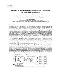
Imperial College London, EEE Department, Exhibition Road, London SW7 2AZ, UK 2 AWE plc, Aldermaston, Reading, Berks RG7 4PR, UK lever is that high stress concentration occurs around the pivot, potentially leading to a reduction in lifespan due to fatigue. This paper reports on a MEMS FPI optical accelerometer with a high resonant frequency which implements a V-beam structure for amplification of the proof mass to enhance sensitivity. To our knowledge this is the first demonstration of an optical accelerometer which uses mechanical amplification to improve performance. A V-beam structure was chosen because it is less prone to stress concentration than pivot-based designs. A schematic of the device is shown in Figure 1. One mirror of the Fabry-Pérot cavity is formed by the cleaved end of the optical fibre, which launches and collects the light, while the other mirror is formed by a gold coated silicon block situated centrally between two angled beams (the V-beam). One end of the V-beam is connected to the proof mass while the opposite end is fixed. When the proof mass is displaced under applied acceleration, the V-beam structure amplifies the displacement and changes the FPI cavity length. In the actual device the fibre is located in an alignment channel formed in the same silicon layer as the moving parts.
ABSTRACT A method is reported for improving the performance of a Fabry-Pérot optical accelerometer, based on the use of a V-beam mechanism to amplify the proof mass displacement. Amplification allows the sensitivity to be increased without compromising bandwidth or requiring an increase in cavity finesse. An analytical expression relating the amplification factor to the V-beam length, width and angle was derived and used to produce a series of differently angled devices. A 1.9° device was capable of detecting accelerations from 0.01 to 10 g rms. The 1.33° accelerometer produced an amplification of 18.6 ± 6.4.
INTRODUCTION Miniature accelerometers typically employ a proof mass supported on an elastic suspension inside a housing. Under an externally applied acceleration, inertial forces cause displacement of the proof mass relative to the housing, and this displacement is measured by an internal transducer. Optical accelerometers are attractive due to their immunity to electromagnetic radiation and their compatibility with harsh environments. Various optical transducers for measuring the displacement of the proof mass have been reported based on optical fibre Bragg gratings [1, 2], intensity based measurement [3, 4] and Fabry-Pérot interferometers (FPI) [5]. Whereas optical fibre accelerometers are constrained by the physical dimensions of the fibre itself, MEMS accelerometers are limited in size only by the micromachining techniques used to fabricate them. As such, they allow greater control over the proof mass and spring constant. Intensity-based devices can be realised by MEMS processing techniques [6, 7] but generally offer lower sensitivities than optical fibre and FPI designs. FPI accelerometers, on the other hand, have the potential for high sensitivity while also being compatible with micro-fabrication [8-10]. For all accelerometer types there is an inherent trade-off between bandwidth and sensitivity. For FPI devices, the sensitivity-bandwidth product can be increased by enhancing the finesse of the optical cavity. However, with MEMS processing this can be difficult due to the high quality finish needed for the mirror surfaces. An alternative approach, investigated in this work, is to amplify the motion of the proof mass. The magnification of small displacements using compliant MEMS structures is well known [11] and has been used previously in applications such as strain sensing [12] and thermal [13] and piezoelectric [14] actuation. Recently, structures that amplify the movement of a proof mass in a capacitive accelerometer have also been developed. Ya’akobovitz and Krylov produced an out-of-plane pivoting lever design with an amplification of 12 [15], while Zeimpekis et al implemented an in-plane lever design with an amplification of 40 [16]. However, the disadvantage of a
978-1-4673-5655-8/13/$31.00 ©2013 IEEE
Figure 1: Schematic of V-beam mechanically amplified optical accelerometer. The following sections discuss the design and modelling of the device, the fabrication process and interrogation method, and the measured performance in comparison with theory.
MODELLING AND DESIGN The operating principle of the V-beam amplifier can be understood using Figure 2, where the V-beam angle has been exaggerated for illustration. The motion of the proof mass causes a compression of the V-beam structure in the x-direction. To accommodate this compression the structure deflects laterally, creating an amplified displacement at the silicon mirror. The two beams securing the mirror are straight when relaxed and constrained to deflect without any end rotation (i.e. as flexures).
609
MEMS 2013, Taipei, Taiwan, January 20 – 24, 2013
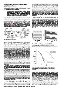
this a thin layer (~200 nm thick) of gold was deposited over the entire device by sputter coating. The role of the gold coating was to increase the reflectivity of the silicon mirror while also removing unwanted cavity effects from the rear surface of the mirror block. Figures 3a and 3b show lowand high-magnification SEM views of a released V-beam, while Figure 3c shows a close-up view with the fibre in place. The notches in the side of the fibre alignment groove were included to aid axial positioning of the fibre.
Figure 2: V-beam amplifier structure. By deriving expressions for the axial compression and lateral deflection of each elastic beam, it is readily shown that the mechanical amplification is given by:
m
y 1 x 2u u
(1)
In this equation u = tan(), and = (w/l)2 where w and l are the width and length of the elastic beams respectively. The variation of m with the V-beam angle has a single maximum which occurs at u , so the maximum achievable amplification is:
max{m}
1 l 4 4w
Figure 3: SEM images showing (a) a released V-beam, (b) detail of silicon mirror and calibration notches, and (c) the FPI cavity formed with the optical fibre.
(2)
where the approximate result assumes l >> w, as is typically the case for the beams in a MEMS device. To assess the validity of equations (1) and (2), a series of devices with differently angled V-beams (0.34°, 0.78°, 1.33°, 1.58° and 1.9°) were designed. The elastic beams were 20 μm wide and 1.5 mm long, giving a maximum expected amplification of around 19 at a V-beam angle of 0.76°. The proof mass was supported by a simple hammock suspension comprising four straight beams of length 0.9 mm and width 20 m. The aim in this work was to produce devices with a resonant frequency greater than 10 kHz. The resonant frequency was determined by an eigenfrequency calculation implemented in Matlab and based on the methods outlined in [17], and the results were verified by two other methods: a Comsol eigenfrequency calculation and a Comsol frequency sweep. The resonant frequency was found to be heavily dependent upon the angle of the V-beam, and this effect was compensated for by adjusting the proof mass dimensions. The silicon mirror was designed to be 125 µm long and 60 µm wide, the width being chosen to ensure negligible bending when the V-beam was deflected. The device was fabricated in a bonded silicon-on-insulator (BSOI) wafer with a mechanical layer thickness of 85 m and an oxide thickness of 2 m. The mirror height was therefore 85 m, and with a 125 m-diameter optical fibre resting on the handle layer the illuminated area of the mirror was roughly 25 m below the top surface.
The optical fibre was positioned using two micro-positioners, one for the device and the other for the fibre; this was done with the aid of a microscope, while monitoring the reflection spectrum using an OSA (optical spectrum analyser). Once the desired location had been achieved the fibre was secured using UV curable glue. The experimental setup used to interrogate the devices is shown in Figure 4. A broadband light source, centrally located around 1550 nm, is band-pass filtered to produce a narrow-band source at a wavelength nominally midway between a maximum and a minimum in the reflection spectrum. Under applied acceleration the reflection spectrum shifts, resulting in a change in the reflected intensity. The accelerometers were secured to a digitally controlled shaker, and the time variation of the reflected intensity was recorded using a photodiode connected to a data acquisition (DAQ) module and a computer running a specifically written Labview program.
Figure 4: Setup used to measure the acceleration and frequency responses of the accelerometers. To measure the dynamic range, the shaker was set to produce a sinusoidal output at 100 Hz with amplitude ranging from 0.01 to 10 g rms. For frequency response measurements, the rms acceleration was fixed and the frequency changed from 6 to 18 kHz in 100 Hz increments. In both cases, a fast Fourier transform was applied to the photodiode signal and the accelerometer reading taken as the amplitude of the fundamental component.
FABRICATION AND TESTING The moving parts and the fibre alignment groove were defined in the mechanical layer of the BSOI wafer by photolithography and deep reactive ion etching. The moving parts were then released by vapour HF (hydrofluoric acid) etching of the oxide layer. Following
610
The 1.33o and 1.9o accelerometers were capable of detecting accelerations as low as 0.01 g rms, the limitation of the shaker used, while the 0.34o device had a minimum detectable acceleration of ~0.06 g rms. All three devices showed a near linear response over the low acceleration range in Figure 6, with any departure from this being attributed to noise. Figure 7 shows the measured frequency response of the 1.33o accelerometer along with the various predicted theoretical values. Arbitrary units are used on the vertical axis to compare the results since the theoretical methods predict only the resonant frequency or the frequency spectrum. The theoretical values are close to that of the experiments with only two points to note: firstly, the Comsol frequency sweep method predicts a higher Q-factor because damping is not properly accounted for; secondly, the predicted resonant frequencies are higher, probably due to differences in device dimensions compared to the design specifications.
A measurement of the amplification factor of each device was also made. This was achieved by forming a second FPI cavity using the gold-coated silicon sidewall of the proof mass and a second optical fibre. The spectra for the mass and V-beam cavities were then recorded using an OSA, first with the mass in its equilibrium position, and then with the mass manually displaced. The changes in cavity length were determined from the recorded spectra and used to calculate the amplification.
RESULTS The acceleration responses from 0.01 to 10 g rms for three devices (0.34°, 1.33° and 1.9°) are shown in Figure 5, while Figure 6 shows the performances of the same devices at low accelerations. From equation (1), these devices are expected to have amplification factors of 13.9, 16.2 and 13.0 respectively, and the sensitivities might be expected to be distributed in a similar manner. However, the overall sensitivity also depends on the mechanical resonant frequency and the finesse (and hence fringe contrast) of the Fabry-Pérot cavity. The marked difference in sensitivity between the 0.34° and 1.9° devices (which are expected to have similar amplification factors) was attributed mainly to differences in cavity finesse. The response of the 1.33° device is limited to 3 g rms due to the intensity based technique being restricted to changes in cavity length below a quarter of the interrogation wavelength. A fringe counting technique, such in phase and quadrature, would overcome this limitation [18].
Figure 7: Frequency response of a 1.33° accelerometer: (a) experimental measurement; (b) Comsol frequency sweep; (c) Comsol eigenfrequency calculation; (d) Matlab eigenfrequency calculation. The measured amplification factors of five devices, along with the theoretical curve based on equation (1), are shown in Figure 8. Taking into account the measurement errors, the experimental results are consistent with theory. The error bars were derived by making multiple estimates of each cavity length using different pairs of fringes in the reflection spectrum.
Figure 5: Acceleration responses of three differently angled accelerometers.
Figure 8: Measured amplification factors for five differently angled devices compared to theoretical curve.
Figure 6: As Figure 5, but with axes expanded to show data at low acceleration levels.
611
[7] B. Guldimann, P. Thiebaud, N. F. de Rooij, and R. A. Turpin, "Micromachined, fiber-optic based accelerometer with shutter modulation," in Tech. Digest of IEEE 13th International Conference on MEMS, 2000, pp. 710-714. [8] K. Zandi, B. Wong, Z. Jing, R. V. Kruzelecky, W. Jamroz, and Y. A. Peter, "In-plane silicon-on-insulator optical MEMS accelerometer using waveguide Fabry-Pérot microcavity with silicon/air bragg mirrors," in Tech. Digest of IEEE 23rd International Conference on MEMS, 2010, pp. 839-842. [9] M. D. Pocha, G. A. Meyer, C. F. McConaghy, S. P. Swierkowski, and J. D. Wolfe, "Miniature accelerometer and multichannel signal processor for fiberoptic Fabry-Pérot sensing," IEEE Sensors Journal, vol. 7, pp. 285-292, 2007. [10] M. A. Perez and A. M. Shkel, "Design and demonstration of a bulk micromachined Fabry-Pérot μg-resolution accelerometer," IEEE Sensors Journal, vol. 7, pp. 1653-1662, 2007. [11] S. Kota, J. Joo, Z. Li, S. M. Rodgers, and J. Sniegowski, "Design of compliant mechanisms: applications to MEMS," Analog Integrated Circuits and Signal Processing, vol. 29, pp. 7-15, 2001. [12] J. Guo, M. Suster, D. J. Young, and W. H. Ko, "High-gain mechanically amplified capacitive strain sensor," in Tech. Digest IEEE Sensors Conference, 2005, pp. 464-467. [13] W. P. Sassen, V. A. Henneken, M. Tichem, and P. M. Sarro, "An improved in-plane thermal folded V-beam actuator for optical fibre alignment," Journal of Micromechanics and Microengineering, vol. 18, paper 075033, 2008. [14] S.-C. Huan and G.-J. Lan, "Design and fabrication of a micro-compliant amplifier with a topology optimal compliant mechanism integrated with a piezoelectric microactuator," Journal of Micromechanics and Microengineering, vol. 16, pp. 531-538, 2006. [15] A. Ya'akobovitz and S. Krylov, "Toward sensitivity enhancement of MEMS accelerometers using mechanical amplification mechanism," IEEE Sensors Journal, vol. 10, pp. 1311-1319, 2010. [16] I. Zeimpekis, I. Sari, and M. Kraft, "Characterization of a mechanical motion amplifier applied to a MEMS accelerometer," J. Microelectromechanical Systems, vol. PP, pp. 1-11, 2012. [17] M. S. William and J. D. Todd, Structures: Theory and Analysis: Palgrave Macmillan, 2000. [18] A. Ezbiri and R. P. Tatam, "Passive signal processing for a miniature Fabry-Pérot interferometric sensor with a multimode laser-diode source," Opt. Lett., vol. 20, pp. 1818-1820, 1995.
The highest amplification measured was 18.6 ± 6.4 for the 1.33° device. In this case there were only three fringes in the wavelength range under examination and this resulted in relatively large uncertainty compared to the other devices. The measurement for the 0.78° device seems anomalous, and it is believed that the V-beam displacement may have been constrained by contact with surrounding silicon, leading to an under-estimate of the amplification factor.
CONCLUSION A MEMS Fabry-Pérot optical accelerometer has been demonstrated which uses mechanical amplification via a V-beam structure to increase performance. An analytical model for the amplification factor has been derived and verified experimentally by fabricating and testing a series of devices with different V-beam angles. The maximum amplification measured was 18.6 ± 6.4 and this was for a 1.33° device. A device with a 1.9° V-beam angle was capable of detecting accelerations from a 0.01 to 10 g rms. The maximum acceleration detectable is currently limited by the intensity-based interrogation method used, and alternative interrogation methods that can overcome this restriction will be investigated in future work.
ACKNOWLEDGEMENTS The authors would like to thank AWE plc for funding this work. © British Crown Owned Copyright 2012 /AWE, published with the permission of the Controller of Her Britannic Majesty's Stationery Office.
REFERENCES [1] T. A. Berkoff and A. D. Kersey, "Experimental demonstration of a fiber Bragg grating accelerometer," IEEE Photonics Technology Letters, vol. 8, pp. 1677-1679, 1996. [2] A. Fender, W. N. MacPherson, R. Maier, J. S. Barton, D. S. George, R. I. Howden, G. W. Smith, B. Jones, S. McCulloch, C. Xianfeng, R. Suo, Z. Lin, and I. Bennion, "Two-axis temperature-insensitive accelerometer based on multicore fiber Bragg gratings," IEEE Sensors Journal, vol. 8, pp. 1292-1298, 2008. [3] A. Llobera, V. Seidemann, J. A. Plaza, V. J. Cadarso, and S. Buttgenbach, "Integrated polymer optical accelerometer," IEEE Photonics Technology Letters, vol. 17, pp. 1262-1264, 2005. [4] G. A. Rines, "Fiber-optic accelerometer with hydrophone applications," Appl. Opt., vol. 20, pp. 3453-3459, 1981. [5] T. Ke, T. Zhu, Y. Rao, and M. Deng, "Accelerometer based on all-fiber Fabry-Pérot interferometer formed by hollow-core photonic crystal fiber," Microwave and Optical Technology Letters, vol. 52, pp. 2531-2535, 2010. [6] J. A. Plaza, A. Llobera, C. Dominguez, J. Esteve, I. Salinas, J. Garcia, and J. Berganzo, "BESOI-based integrated optical silicon accelerometer," J. Microelectromechanical Systems, vol. 13, pp. 355-364, 2004.
612