This paper describes in detail the design, development, and evaluation of the TWISTER III (Telexistence Wide- angle Immersive STEReoscope) and ...
Please see the color plates on page 278
TWISTER: An Immersive Autostereoscopic Display Kenji Tanaka Junya Hayashi Masahiko Inami Susumu Tachi Graduate School of Information Science and Technology, The University of Tokyo {tanaken, junya, minami, tachi}@star.t.u-tokyo.ac.jp
Abstract This paper describes in detail the design, development, and evaluation of the TWISTER III (Telexistence Wideangle Immersive STEReoscope) and demonstrates how this system can display immersive three-dimensional full-color and live motion pictures without the need for special eyewear. The device works as a cylindrical display by rotating 30 display units around an observer and presenting time-varying patterns, while immersive autostereoscopic vision is achieved by employing a “rotating parallax barrier” method. After explaining the principle, we discuss the designs and implementations for maximum performance in various aspects of the display. We also evaluate the display.
pable of simultaneously displaying a stereoscopic image to two or more people, Eichenlaub et al. developed a multiplezone autostereoscopic display using an ICFLCD with lookaround capability. NHK developed a system that uses realtime full-color integral photography with an HDTV camera and an optical fiber array[7]. This system requires a tradeoff between resolution and the directional variance of the light. Autostereoscopic systems and their characteristics are listed in Table 1. Table 1. Autostereoscopic displays TWISTER Perlin et al. SANYO Eichenlaub IP television Holographic
1. Introduction
immersive
autostereo
live motion picture
one-tomany
vertical parallax
+ -
+ + + + + +
+ + + + -
+ + +
+ +
1.1. Immersive autostereoscopic display overview 1.2. Overview of TWISTER To date, there have been many displays proposed as suitable systems for Virtual Reality (VR). Some displays offering a high sense of presence are called immersive. There are several varieties of Head-Mounted Displays (HMDs)[1], optical systems carried by the user, and immersive multiscreen display units such as the CAVE[2]. However, since most systems require special glasses for stereopsis, these systems pose difficulties in photographing the user’s face and cannot be used for face-to-face applications such as an interview[3]. Many trials have been performed to address this particular problem. The display in question is called an autostereoscopic display. The MIT Spatial Imaging Group[4] used 3D computer-generated holographic images reconstructed in real time using acousto-optic modulation of light. However, the spatial resolution was very low. Parallax barriers and lenticulars have also been used in a number of systems. Perlin et al.[5] developed an autostereoscope by using a picell electronic light shutter, while Sandin et al.[6] used a variable barrier screen (Varrier). For a system that is ca-
IEEE Virtual Reality 2004 March 27-31, Chicago, IL USA 0-7803-8415-6/04/$20.00©2004 IEEE. Proceedings of the 2004 Virtual Reality (VR’04) 1087-8270/04 $ 20.00 IEEE
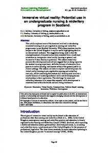
The goal of this project is to develop an 1) immersive, 2) autostereoscopic, and 3) live and interactive full-color motion picture display. As a solution to this target, three prototypes of this type of immersive display have been developed so far : TWISTER I, II[8][9], and III. TWISTER III works as a cylindrical display by rotating 30 display units around the observer while preserving timevarying patterns. Each of these display units contains two LED arrays, a vertical 1D array for the left eye and one for the right eye, and a thin barrier. The units rotate at a speed of about 60 revolutions per minute (rpm), and the controller synchronizes the display update to create an effective frame rate of 30 frames per second (fps). With the ability to encode eight NTSC inputs, TWISTER meets the criteria for an immersive display that can present live full-color motion pictures. In order to meet the criterion of autostereoscopic viewing, we adopted the “rotating parallax barrier” method. Figure 1 shows the principle of the “rotating parallax barrier.” A thin metal barrier (parallax barrier) is arranged in
59
front of two LED arrays. This barrier interrupts the luminescence of the emitted light on the complimentary side, so each array is visible only to the eye on the corresponding side. At one moment, only the images for the left eye and right eye are observed in areaL and areaR , respectively. Both images are observed in areaB , and neither image is observed in areaN . When the display units (including the occluders) rotate around the user, these areas also rotate with the display. The regions in which the left and right eyes must be placed are defined so that all of the inner points are always included in areaL or in areaR while the cylinder rotates for a range of angle of rotation. Therefore, the regions are dependent on the desired horizontal field of view. As long as the eyes are in the regions, cylindrical stereo images are shown to the observer. First in Section 2, we discuss the system’s design and performance, derived from the features of TWISTER III. Some topics include the empirical knowledge we obtained through exhibitions and demonstrations. The implementation details are elaborated upon in Section 3, followed by topics of image acquisition and generation (Section 4). In Section 5, we evaluate the stereoscopic presentation capability of TWISTER III. The specifications of TWISTER I, II and III are listed in Table 2.
2. Design and performance 2.1. Field of view The horizontal field of view (FOV) of humans exceeds 180 degrees. Since there are 140 degrees of binocular vision, a stereo display should present a FOV of at least 140 degrees. With traditional stereoscopic displays such as HMD and IPT, the stereo glasses narrow the FOV for stereopsis. Even with wide FOV HMDs, the FOV is 90 degrees to 120 degrees. When one tries to look at an object with binocular vision (stereopsis), the FOV is about 90 degrees, at most. TWISTER has a wide display domain that covers the human FOV of binocular and monocular vision. From the detailed discussion of the FOV in Section 2.4, we can conclude the stereoscopic FOV of TWISTER exceeds 140 degrees. In addition, since peripheral vision is important for the sense of motion, TWISTER is especially suitable for motion-picture presentation. The vertical FOV of TWISTER III is 64 degrees. It is designed so that it can display the upper half of a human body at a distance of two meters. The selected height of the eyes is above the midpoint of the LED arrays in order to increase the display region below that level. The vertical FOV of humans is greater below that level.
2.2. Color reproduction and tonal resolution The color reproduction and the tonal resolution are determined by the light emitting device and the method of driving the device. By using RGB triplet LEDs (E1S101W-3in1-lens from Toyoda Gosei), it is possible to achieve a bright, high-contrast ratio display with full-color reproduction especially rich in red. This is one of the advantages compared to other displays using projectors and Cathode Ray Tubes (CRTs). We have confirmed that TWISTER can be used even in a well-lit room with a maximum luminance of 740 cd/m2 .
Figure 1. Rotating parallax barrier
2.3. Spatial resolution and frame rate Table 2. Specifications of TWISTER Specification Horizontal # of pixels / 360 deg Visual acuity Vertical # of pixels / 360 deg Visual acuity Temporal resolution (frame/s) Horizontal FOV (deg) Vertical FOV (deg) Color expression Radius of the rotator(mm) Speed of rotation (rpm) Stereopsis
I 960 20/70 128 20/400 Still image 70 40 Red only 600 60 Possible
Proceedings of the 2004 Virtual Reality (VR’04) 1087-8270/04 $ 20.00 IEEE
II 1,080 20/400 128 20/400 Still Image 90 40 RGB 24bit 600 60 Possible
III 1,920 20/220 256 20/330 30 90 64 RGB 24bit 800 60 ~ 90 Possible
The horizontal resolution acuity is 20/200 based on the luminescence period of LED and the rotation speed, while the vertical resolution acuity is 20/400 based on the packaging density to the substrate of LED. With these resolutions, we confirmed one can roughly distinguish the facial expression of a human at a distance of two meters (Figure 11 left). One option for improving the horizontal resolution is to vary the resolution according to the region of interest of the observer. This variation works since human visual acuity in the circumference region falls sharply. By using a diffuser, the image quality is improved. However, the resolutions have room for improvement.
60
We employed the NTSC format (including both interlace and progressive sources) with a frame rate of 30 fps, similar to that of many other displays. Video driver units were designed in order to present motion pictures.
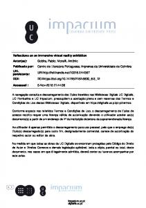
2.4. Head position Since TWISTER is an autostereoscopic display, it is possible in principle to present a precise stereoscopic image by reproducing the incident rays to the eyes. However, there is no flexibility of head rotation in that situation. We have made efforts to allow flexibility of head rotation without tracking the observer’s head. In this section, we analyze the effect of head movement (translational and rotational) on the observed images. Head tracking has two implications: 1) the generation of images according to the head position and 2) controlling rays so that autostereoscopic presentation can be performed. For the first issue, one possibility is to generate images so that the displayed image is always accurate only for the user’s front even if his/her head rotates. This kind of rendering is called panoramic stereo or omni-stereo image acquisition[10]. This methodology makes the absence of head tracking an advantage rather than a shortcoming: the motion pictures prepared for TWISTER can be observed for any direction. We further discuss the rendering issues in Section 4. For the second issue, some methods to keep the allowable head position and direction large are introduced in the next paragraphs. Image separation The main parameters that affect the viewing condition are the distance between two LED arrays and the width of the parallax barrier. More precisely, since LEDs have width, areaL does not border on areaR , but there is a buffer zone where the light from both the left and right arrays are visible. Figure 2 shows the photograph of a screen with 1 cm ticks placed at the center of TWISTER when illuminated with only the left array (left) and the right array (right). The width of the buffer zone is estimated at about 2 cm from this measurement.
Translational head movement Shown in Figure 8 is the plot of the observable eye positions by translational movement for a certain stereoscopic FOV. The plot has a diamond shape, and its diagonal length can be approximated using straightforward algebra: a = i/2 − z/(2 sin θ ), b = i/(2 tan θ ) − z/(2 sin θ ), where i is the interpupilar length and z is the width of the buffer zone mentioned above. The maximum θ (stereoscopic FOV) is calculated as θmax = cos−1 (z/i). It is 72 degrees for the typical interpupilar length of 65 mm, when z = 2cm. This system qualifies since the total FOV becomes 144 degrees. It is important to determine the width of the barrier so that z is minimum. Head rotation The effect of “looking around,” i.e., “rotation of the head” can also be taken into further consideration. Figure 9 shows how the possible observation area changes with the rotation of the head. In the top view, we consider half lines that start from the LED arrays on either side and pass along the right and left edges of the parallax barrier. They are henceforth called area division lines. If we place the intersecting point of the area division lines at the center of TWISTER (left), the head rotation angle is limited to about 15 degrees on each side in this case because the midpoint of both eyes is not the center of head rotation. When we put the intersecting point beside the center, the possible observation area (the diamonds) becomes smaller, and we can rotate the head as much as 30 degrees on each side. This is a trade-off problem. In the former case, the FOV for stereopsis is large at θ = 0, but head rotation is not allowed. In the latter case, on the other hand, head rotation is allowed to some extent, but the FOV for stereopsis for each θ becomes smaller. In this case, it is also possible to use TWISTER as an ordinary two-dimensional immersive display of 360 degrees since for any θ particular points are in areaB . Among these variations, the actual parameter was selected to be between two situations after trials. Practically, the issue of observable head position is not very serious. When the eyes are temporarily out of the sweet spot, one of the eyes always enters the above-mentioned buffer zone. Since the lighting intensity of the buffer zone is comparatively high and the observer can perceive the area borders, he/she can find the best position easily. Six people of a total of 1100 viewers pointed out this issue.
2.5. Rotation speed Figure 2. Actual shadow pattern of the barrier when illuminated by only right and left LED arrays.
Proceedings of the 2004 Virtual Reality (VR’04) 1087-8270/04 $ 20.00 IEEE
There are several factors to determine the rotation speed. In this section we focus on four major factors: flicker, the saccade effect, circular vection, and the time lag between two eyes. The radius of the cylinder was set at 0.8 m
61
after conducting a preliminary experimentation of the accommodation-convergence relation[9]. Flicker and saccade effect The minimum presentation frequency where one does not notice flickering is at least 60Hz, though it depends on the brightness. In order to comply with this condition, with 30 display units, the rotation of TWISTER was designed to be 120 rpm. We have confirmed that the rotation speed could be raised to 120 rpm without turning on LEDs and to 90 rpm with LEDs on. Theoretically, if the rotation speed of TWISTER is equal to the maximum angular speed of saccade (rapid eye movement), the LED arrays are perceived as a stationary object. At a speed higher than the speed of saccade (500 to 600 degrees per second), this phenomenon can be avoided. Circular vection A subject who stands inside a spinning drum perceives that he is spinning in the opposite direction. This effect is called circular vection. When the spinning speed is low (2 to 100 degrees per second), a linear relationship exists between the speed of the drum and the perceived speed induced by circular vection[11]. At the adopted speed of 60 (rpm), it is supposed that this effect can be effectively avoided. However, some of the users reported dizziness while in the booth. Some people felt a sense of incongruity with head motion and with eye movement in the same direction as the display’s rotation. The complex intricacies of saccade effects and circular vection remain somewhat elusive. Time lag between the left eye and the right eye With TWISTER, in principle, the presentation of two images does not occur simultaneously; however, the respective images are shown simultaneously when the eyes are located in areaL and areaR . When the rotation is 60 rpm, the duration of simultaneous vision can be evaluated at 300 to 500 msec, which is long enough to produce the desired effect. In fact, stereo perception is possible for rotation speeds as low as 42 rpm, which confirms a previous report[12] stating that stereo perception is possible when the left image and the right image are displayed simultaneously for at least one moment. Safety and robustness The sound generated by rotation was 75 dB measured at the position of the user’s ears and 60 to 68 dB outside the booth when the rotation speed was 60 rpm. This noise level was equivalent to that found in a slightly noisy restaurant. Since TWISTER is intended to be used in a public place such as a
Proceedings of the 2004 Virtual Reality (VR’04) 1087-8270/04 $ 20.00 IEEE
convention center, this level is not overly distracting. Wind is also generated outward, but practically it does not disturb the observer or the people outside the booth. One design option is to hang the rotator from its axle from a large framework as adopted in TWISTER II. This decreases the noise level considerably.
3. Implementation 3.1. Mechanism
The mechanical structure was simplified as much as possible to increase its robustness. Moreover, for portability, it was designed to be assembled and disassembled easily. TWISTER is composed of a cylindrical framework and a stand that supports and drives it. We henceforth call the cylindrical framework the “rotator.” The whole structure is shown in Figure 10 (left). Made of aluminum, the rotator is light (less than 70 kg) and rigid. It consists of upper and lower round rings, 30 display units, 30 support pillars, and a slip-ring support component. The top and bottom rings are made from thick aluminum plates processed precisely by a milling machine. Each pillar supports a display unit. The medial height of the display unit is set at 1700 mm. Each part, such as the LED boards, was designed for easy maintenance. In order to determine the presentation position of an LED pixel with sufficient accuracy, the attachment position of a substrate can be finely tuned. Clear acrylic protection walls are located on the inside and the outside to prevent a user from touching the rotator. Furthermore, an antireflection film is put on the inside to prevent the light of the LED behind the user from being reflected on the inside cylindrical protection wall. A slip-ring is supported by a rotator, and the wiring for free rotation is fixed by a beam on the upper part of a protection wall. Motors (150W DC motors from Maxon Motor Corp.) and rubber-molded drive rollers were installed in the upper corners of the stand to drive the rotator. Moreover, eight guide rollers were installed so that the rotator can be fixed vertically and fixed along the radius direction. Shown in Figure 10 (right) is the illustration of the drive rollers and the guide rollers. Thanks to the precise manufacturing of the framework, the time jitter of the display surface along the radius of the cylinder is very subtle (under 0.5 mm over one revolution). The horizontal jitter of the display pixel along the display surface is within one pixel (under 2 mm), which is not distracting. The precision of the structure improves not only the quality of the image but also the stereo presentation performance.
62
3.2. Display unit and video driver
Use of diffuser
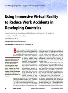
On one display unit, 512 LEDs (256 for the left, 256 for the right) are implemented with a pitch of 3.75 mm on two vertically connected LED boards (Figure 3). The total length is 960 mm and the total number of vertical pixels is 256 for each eye. In this section, the details of the display unit are described. 56 200 42 LED arrays
LED with lens
480 3.75
parallax barrier
1.2
(mm)
Figure 3. Display unit
Video signal and driver units Without regard to whether the image is computer-generated, captured, or played back, four NTSC video signals are used to reproduce the images. After inverse gamma compensation[9] is applied, the video signals are synchronized using four synchronized time base correctors (A-30 from FOR-A Corp.), and transmitted inward the rotator via the slip-ring (S70 from JAPAN SERVO) of 32 poles. The total window of 1920 x 256 pixels (whole cylindrical screen) is virtually divided into four partitions at 90degree intervals, and the images for the right and left eyes for each region are transmitted in one NTSC signal. As the vertical scanning period is shorter than the horizontal scanning period, unlike ordinary NTSC, the scanning line of the TWISTER is vertical and sweeps from right to left. The NTSC signals are processed and converted into digital signals (LVDS) by two (for left and for right) NTSC decoder boards (VP-1018 from ViewPLUS) on the rotator. The signals are then processed and distributed to LED controllers with a video driver unit (VP-1019 from ViewPLUS). The video data are updated every 1/30 seconds and displayed on the LED array according to its position. The position is detected using the impulse signal from a photo interrupter placed at the circumference of the cylinder and dividing the period into sufficient resolution. The total number of pixels for one frame is 1920 × 256 = 491520 pixels, which corresponds to a total data rate of 84.4 MB/sec for both eyes. The image data are transmitted in the LVDS signal by a 108 MB/sec data bus.
Proceedings of the 2004 Virtual Reality (VR’04) 1087-8270/04 $ 20.00 IEEE
The graininess of LEDs is not only annoying but also may have bad effects on depth perception. To avoid such a problem, diffusers are arranged in front of the LED arrays. After considering various materials for a diffuser, we used double-piled mending tape (3M Corporation). The diffuse film was attached parallel to the LED array at a distance of 23 mm so that the LED grain cannot be seen. Figure 11 (right) shows the effect of diffuser. With a diffuser, the brightness of the display is reduced by roughly half that of the original, but this is not a problem because the LED can be made brighter. In the picture, there is also an observable difference between the vertical blur and the horizontal blur because the LED flashes periodically in an impulse-like transition, and the edge of the horizontal blur is almost always cut sharp with the barrier edge.
4. Image generation In rendering for TWISTER, we have to consider the problem of displaying a panoramic stereoscopic image without head tracking. In order to address this problem, we discuss two kinds of rendering in this section. We can apply the following discussion both to Computer Graphics (CG) and to real scenes.
4.1. Two modes of rendering One mode of rendering, which we call Mode 1, assumes that the user’s head does not move at all. In this mode, the image is precise for one direction, but there is no flexibility of head rotation. In another mode, which we call Mode 2, the generated image is always accurate only for the user’s front even if his/her head rotates. This kind of rendering is also called concentric mosaics[13]. In this mode, we assume that the user’s head moves by one degree of freedom along a specified orbit. Shown in Figure 4 are the rendering diagrams of Mode 1 and Mode 2. The coordinate system has its origin in the center of TWISTER and is right-handed with respect to the floor. In the figure, the midpoint of both eyes coincides with the center of TWISTER, but this is not necessary. Whichever direction the user turns, the correct light information will come at least from the front. The light information coming from other directions is just an approximation in this mode. Depth presented in Mode 2 As mentioned above, the light information that comes from directions other than the front is just an approximation and
63
y
Mode 1 d P1L
d
Q1
Q2
P1R P2L
ex
θ' r
Q1
P1L
P2R
θ
-ex
y
Mode 2
Q2
P1R P2L P2R
θ x
5 m, and the fact that when one’s head is free, the scope in which one focuses on objects with saccades is within 15 degrees[14], the depth distortion does not cause a serious problem, and this mode can also present a sufficient sense of immersion. We also confirmed this fact from visual observation.
-ex
ex
O
θ' r
x
O φ
φ φ = 0 φ = 15
4.2. Practical rendering In order to photograph a still panoramic stereo image, we panned two cameras separated by 65 mm, or the average human interpupilar distance, and composed the captured images (Figure 13 left). On the other hand, we simulated the camera directions with 32 different projection matrices in order to render a dynamic panoramic stereo image in real time CG (Figure 13 right). To be more precise, the images should be generated (or captured) according to the height of the eyes and the interpupilar distance of the viewer. Because many people don’t move their head up and down during the experience, the problem of vertical parallax can be mostly alleviated by doing so.
φ = 30
1 φ = 60 d: 0.5m 0.67m 0.8m 1m 1.33m 2m 4m
0.5
0
0.5
1/d' 1/d
1
1.5
Figure 4. Rendering diagrams (upper) and Depth presentation in Mode 2 (lower).
includes error. In this subsection, we calculate the depth presented in Mode 2, when the user turns his/her head in a certain direction φ . We can calculate the distance of the object (d) as follows: 1 1 sin θ 1 sin θ = − cos θ � − d r ex ex r
(1)
where ex is half of the interpupilar distance of each subject, θ is the angle of � P1R OQ1 , and r is the radius of TWISTER as defined in Figure 4 (upper). When the point is in the direction of φ , the distance to the object d � can be estimated as 1 1 sin θ � � − (2) � d r ex cos φ since the half-interpupilar distance is approximately e�x = −→ ex cos φ . Since θ is constant for any direction if |OQ| is constant in Mode 2 rendering, the distortion of Mode 2 rendering of a concentric circle can be estimated using θ � = θ as follows: � � � � 1 1 1 1 sin θ 1 θ = − − 1 � − − 1 (3) cos φ ex d� d d ex cos φ �
Figure 4 (lower) shows 1/d 1/d for a certain φ and d, which is the distortion of depth presentation in Mode 2. It is confirmed that for a certain d larger than the radius of TWISTER, the depth can be estimated to be larger, and for a certain φ , d � becomes infinite. Although the depth is estimated to be larger, the error is within 15% when |φ | < 15 degrees and d < 4 m. From the above discussions, the fact that depth perception with convergence is valid under
Proceedings of the 2004 Virtual Reality (VR’04) 1087-8270/04 $ 20.00 IEEE
4.3. Spatio-temporal sampling pattern In TWISTER, since the LEDs are rotating, if a progressive source such as a film is shown, a luminescent spot will appear in the portion where the real object does not exist, and vice versa. This phenomenon is peculiar to a rotating display like TWISTER. On a revolving display, each image of a dynamic scene (such as a film or NTSC) will be presented by an LED that travels over 12 degrees in 1/30 seconds. It causes the pixel to be displayed in portions that were unintended. Figure 5 shows this situation. If a portion of a stripe is not located on one straight line, it is perceived as a jitter (left). In more severe cases, an object may appear to be divided. A measure to counter this phenomenon is to show only suitable picture information, which should be acquired exactly along the LED path (right). In other words, we have to adopt a spatio-temporal sampling pattern other than ordinary film. By using CG, this problem can be solved by refining the time unit. If we use a real scene, the continuous image information between the discrete frames must be estimated in some way. However, this is not a serious problem for an object that travels slow enough (e.g., under 30 degrees/sec).
5. Stereo vision performance 5.1. Stereopsis presentation The actual stereoscopic image presented is shown in Figure 12. By visual observation, stereopsis was achiev-
64
frame 1 data in the film frame 2 LED path frame 3
on
off
t
0.75
PSE in Depth Perception
Depth Perception
1
0.5
Depth of real indicator 50cm 1m 1.33m 2m 4m
0.5 0.3
0.4
0.5
0.25
1.0
2.0 4.0
Perceived Depth (m)
real object path
Proportion of judgements
Without compensation With compensation h h
frame 0
PSE regression line y=x
1 1.33
Intended Depth (m)
Figure 5. Spatio-temporal sampling.
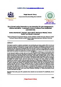
5.2. An experiment on depth perception We performed some experiments in order to further evaluate the performance as a stereoscopic display. In the first experiment, we had the subjects compare the depth of the real indicator with the displayed indicator. The real indicator was a green LED placed outside the booth, and the luminescence part was masked or diffused so that the luminosity and size roughly equaled that of the displayed indicator. The visual angle of the luminescent spot of TWISTER was under 15 minutes. The rotation was controlled to be 60 ± 1.8 (rpm). We adopted the method of constant stimuli. The displayed indicator was shown with a random depth, while the real indicator was at a fixed distance in 20 continuous trials. The subject’s head was fixed using a jaw stand at a height of 1600 mm above the ground; the real and displayed indicators were located at the same height. One sequence has a period of 6.0 seconds: 1.5 seconds TWISTER indicator, 1.0 second darkness, 1.5 seconds real indicator, and 2.0 seconds darkness. The visual acuity, the interpupilar distance, and stereo acuity of the subjects were measured beforehand. The displayed depth was calculated using the equation(1). Figure 6 (left) is the plot of the proportion of judgments that the displayed indicator is farther than the real indicator. The horizontal axis indicates the displayed depth. Shown in Figure 6 (right) are the error plots of Point of Subjective Equality (PSE), the point (50%) at which the proportion of judgments in which the displayed indicator is farther, and the range within which the proportion of judgments is 25% to 75%. Added to the plot are the regression line and the line where the two values are the same. With
Proceedings of the 2004 Virtual Reality (VR’04) 1087-8270/04 $ 20.00 IEEE
4
+infinity +infinity 4
0
able. Unlike typical parallax barriers, stereopsis was possible with almost no cross talk. By calculating the Fraunhofer diffraction with a slit, the influence of the diffraction can practically be ignored since the size of the diffraction pattern is theoretically less than x = 4 × 10⁻³ mm. In the measurement of the illuminance mentioned above (Figure 2, right), the illuminance at the position of the unilluminated eye was under the detection limit of 0.5 lx, that of darkness.
2
2 1.33 1
0.5
Dispalyed Depth (m)
Figure 6. Depth perception with TWISTER (left) and PSE in depth perception (right).
this plot, it is shown that, in the assumed range of 0.5 m to 3 m, the depth is perceived in a linear relation with the displayed depth. As causes of the shift in perceived depth, we can consider 1) the window-frame effect caused by the graininess of the LED, 2) the inadequate resolution, and 3) the inconsistency between convergence and accommodation. Since we used diffusers and not sub-pixel rendering in this experiment, we suspect 3) to be the main reason. From Donders’ line (the accommodation-convergence relation), it is hard to fuse by convergence an object at a distance of 5 m or farther when the screen is set at a distance of 0.8 m. However, it is possible when the screen is set at 1 m. We retested this experiment, selecting screen distances of 0.8 m, 1 m, and 1.2 m, and obtained the same results. In order to eliminate the possibility of accommodationconvergence mismatch, we tried to observe the display using glasses for farsightedness (0.25 diopter) and confirmed that in this case, we perceived the displayed indicator to be farther than 4 m. Since in our application of face-to-face communication, the maximum depth is assumed to be about 3 m, we can conclude the display qualifies. It is presumed from the experiment using glasses for farsightedness that the radius of the display extends the maximum depth that can be displayed.
5.3. Limit of fusional vergence The limit of fusional vergence was measured in order to investigate to what scope of depth one can fuse an image with vergence and judge the depth with stereopsis. In this experiment, a pattern of double circles with a disparity of 22.5 min/arc was displayed at the intended distance of 5 cm to infinity. The results are shown with the p of the doublesided t-test in Table 3. The proportion of correct answers is over 80% in the range of 50 cm to infinity. It can also be proven that one can judge the relative depth of multiple objects displayed with TWISTER at the assumed distance from 0.5 m to 3 m.
65
Acknowledgement
Table 3. Subject accuracy displayed depth 0∼12 cm 12∼50 cm 50 cm∼1.33 m 1.33 m∼ ∞ ∞ ∼ (divergence)
front 7% 62% 80% 85% 67%
p < 0.5 < 0.001 < 0.001 < 0.001 < 0.004
back 67% 100% 100% 93% 100%
p < 0.001 < 0.001 < 0.001 < 0.001 < 0.125
6. Conclusion TWISTER has proven to be an effective and promising display in VR. TWISTER achieves our goals for an 1) immersive, 2) autostereoscopic, and 3) live and interactive full-color motion picture display. 1) Immersion: After a detailed discussion, we concluded the stereoscopic FOV of TWISTER exceeds 140 degrees, which is enough for the sense of presence, and was not achieved with conventional IPT- or HMD-type displays. 2) Autostereopsis: We also achieved autostereoscopic presentation with almost no cross talk. In an experiment, it was proven that TWISTER can be used for linear depth presentation at a distance of 0.5 m to 3 m, which is required in face-to-face communication. It was also proven that one can fuse an image with vergence and judge the relative depth of multiple objects at a distance of 0.5 m to 3 m with a disparity of at least 22.5 min/arc. 3) Live and interactive full-color motion picture: We achieved 30 fps, 24bit full-color motion picture presentation with a total of 1920 × 256 pixels for each eye. Thanks to LEDs, bright(740 cd/m2 ) and rich color reproduction was also made possible. As for the design issues that we must address, we have listed flicker, the saccade effect, circular vection, the time lag between eyes, and the accommodation-convergence relationship. In association with the absence of head tracking, we have tried an option of omni-stereo rendering. The spatio-temporal sampling pattern was discussed as an issue peculiar to a rotating display. Regarding implementation, we enumerated some hurdles which have been overcome: stable rotation of the cylindrical framework, fast data transfer and distribution for motion pictures, and some improvement of the image quality. Future subjects for study include improvement of spatial resolution, reduction of flicker, and reproduction of long distance depth. We are also planning to develop an image sensor for panoramic stereo motion picture acquisition. Using the sensor, one-to-many communication with a sense of presence will be possible. With image data transmitted from a sensor carried by a remote robot, viewers in remote booths (cockpits) can view the same objects or scenes at the same time in arbitrary ways. Such an application can be available because stereo pictures are shown without head tracking.
Proceedings of the 2004 Virtual Reality (VR’04) 1087-8270/04 $ 20.00 IEEE
This research has been supported by the CREST project of JST (Japan Science and Technology Agency).
References [1] I. E. Sutherland. The ultimate display. In Proceedings of IFIP Congress, pages 506–508, 1965. [2] C. Cruz-Neira, D. J. Sandin, and T. A. DeFanti. Surroundscreen projection-based virtual reality: The design and implementation of the CAVE. In Proceedings of SIGGRAPH 1993, Computer Graphics Proceedings, Annual Conference Series, pages 135–142. ACM, ACM Press / ACM SIGGRAPH, 1993. [3] S. Tachi, T. Maeda, Y. Yanagida, M. Koyanagi, and H. Yokoyama. A method of mutual tele-existence in a virtual environment. In Proceedings of ICAT 96, pages 9–18, 1996. [4] S. A. Benton. Experiments in holographic video imaging. In P. Greguss, editor, Proceedings of the SPIE Institute on Holography, volume IS#08, pages 247–267, 1991. [5] K. Perlin, S. Paxia, and J. S. Kollin. An autostereoscopic display. In Proceedings of SIGGRAPH 2000, Computer Graphics Proceedings, Annual Conference Series, pages 319–326. ACM, ACM Press / ACM SIGGRAPH, 2000. [6] D. J. Sandin, T. Margolis, G. Dawe, J. Leigh, and T. A. DeFanti. The Varrier auto-stereographic display. In Stereoscopic Displays and Virtual Reality Systems VIII, Proceedings of the SPIE, volume 4297, pages 204–211, 2001. [7] F. Okano, H. Hoshino, J. Arai, and I. Yuyama. Real-time pickup method for a three-dimensional image based on integral photography. Applied Optics, 36(7):1598–1603, 1997. [8] Y. Kunita, N. Ogawa, A. Sakuma, M. Inami, T. Maeda, and S. Tachi. Immersive autostereoscopic display for mutual telexistence: TWISTER I (Telexistence Wide-angle Immersive STEReoscope model I). In Proceedings of IEEE VR 2001, pages 31–36. IEEE, 2001. [9] K. Tanaka, J. Hayashi, Y. Kunita, M. Inami, T. Maeda, and S. Tachi. The design and development of TWISTER II: Immersive full-color autostereoscopic display. In Proceedings of ICAT 2001, pages 56–63, 2001. [10] S. Peleg, M. Ben-Ezra, and Y. Pritch. Omnistereo: Panoramic stereo imaging. IEEE Trans. on PAMI, pages 279–290, 2001. [11] B. DeGraaf, A. H. Wertheim, and W. Bles. Angular velocity, not temporal frequency determines circular vection. In Vision Research, volume 30, pages 637–646, 1990. [12] K. N. Ogle. Stereoscopic depth perception and exposure delay between images to the two eye. In J. Opt. Soc. Amer., volume 53, 1963. [13] H. Y. Shum and L. W. He. Rendering with concentric mosaics. In Proceedings of SIGGRAPH 1999, Computer Graphics Proceedings, Annual Conference Series, pages 299–306. ACM, ACM Press / ACM SIGGRAPH, 1999. [14] A. T. Bahill, D. Adler, and L. Sterk. Most naturally occuring human saccades have magnitudes of 15 deg or less. In Investication of Ophthalmology, volume 14, pages 468–469, 1975.
66
Color plate of paper TWISTER: An Immersive Autostereoscopic Display on page 59
rotation slip ring acrylic tube (fixed part)
lower ring
rotator display unit
stand (fixed part)
guide roller motor
Figure 10. Structure of TWISTER III (Whole part and closer look of the rotator and the rollers). Figure 7. An observer experiencing TWISTER
top view
θ
Center of TWISTER
b a
interpupilar distance
Figure 11. Actual image presented on TWISTER III(left)/ Diffused (lower) and nondiffused (upper) image(right).
Field of view for stereopsis: 30 degrees 60 degrees 90 degrees
Figure 8. Observable eye positions for a certain stereoscopic FOV.
top view
Left image
Intersecting point for θ= 0
Figure 12. Stereoscopic presentation field of view (left eye) point of view (left eye)
Center of TWISTER Center of head rotation
Area B
180
225
left
Field of view for stereopsis: 30 degrees Head rotation 0 degree 15 degrees 30 degrees
right
Figure 9. Head rotation and the observable eye positions.
Proceedings of the 2004 Virtual Reality (VR’04) 1087-8270/04 $ 20.00 IEEE
Right image
Figure 13. Variety of point of view and eld of view of left camera (left) and constructed CG panoramic image(right).
278
deg 270