vorticity and can be thought of as an infinitely small whirlpool. When all these small whirlpools are added together the final flow pattern arises. Vortex particles.
Two-dimensional simulation of gaseous phenomena using vortex particles Manuel Noronha Gamito Pedro Faria Lopes Mário Rui Gomes INESC, Rua Alves Redol, 9, 2º, 1000 LISBOA E-Mail: {mag|pfl|mrg}@inesc.pt
Abstract. This article presents a simple, fast and stable method for the animation and visualisation of turbulent gaseous fluids in two dimensions. We draw on well known methods from computational fluid dynamics to model the fluid using vorticity and velocity fields. While the vorticity is transported by a particle system, we use a uniform grid to compute velocities and displacements for each particle. This mixed approach where free particles move on a fixed grid requires little computational power, making it suitable for computer animation. The method simulates the behaviour of fluids in situations where the contact between fluid masses with different velocities generates an intermediate mixing layer which can give rise to turbulence phenomena. Unlike previous algorithms, it is possible to generate quasi-turbulent patterns, where large scale coherent vortex structures are still discernible in the flow.
1 Introduction The modelling and animation of fluids are among the greatest challenges anyone working in computer graphics can face. Fluids are a constant presence in our lives, from the water that covers two thirds of our planet to the air that surrounds us. There is an understandable desire to portray such objects side by side with other more tractable geometric objects. In this article a method is presented for the animation and visualisation of gaseous fluids based on a vorticity model [12]. The vorticity is a measure of the amount of circulation of the fluid at each point in space. If the vorticity field is known at some instant it is possible to obtain its evolution for all subsequent instants. The vorticity field is represented with a particle system [14]. A vortex particle (also know as a vorton in the computational physics literature) carries around a given amount of vorticity and can be thought of as an infinitely small whirlpool. When all these small whirlpools are added together the final flow pattern arises. Vortex particles continually form and evolve over time, giving rise to highly complex and appealing motions. Common examples can be a column of smoke rising through the air or the foam pattern a ship's propeller leaves behind it on the water. We use a regular grid to store an equivalent sampled version of the vorticity field. A velocity field is calculated over the grid as the solution to a Poisson equation with suitable boundary conditions. The particles are then advected according to this
velocity field. This method is particularly useful for the simulation of fluid flows with low viscosity and in the presence of large velocity gradients. This type of flows is characterised by small regions of concentrated vorticity, which can eventually become turbulent. At present, the method is only applicable for two dimensional flow fields. It has, however, very low computational costs and can handle systems with large numbers of particles, which makes it an attractive method for the generation of complex animated textures. Such textures can then be mapped onto the surface of three-dimensional objects, much like Gardner's textures [8].
2 Previous Work Several models for fluid flow including turbulent effects, have already been presented in the literature. In early works, turbulence was functionally defined as the superposition of band-limited noises over consecutively smaller scales [13]. This adhoc definition of turbulence was used for the synthesis and animation of clouds [7,16]. The results, although quite good for static images, were forcefully unrealistic when it came to simulating the dynamics of the clouds. Yaeger was the first to use a vorticity model in computer graphics to animate the atmosphere of the planet Jupiter [23]. The vorticity field, corresponding to an initial cloud pattern, was sampled on a grid and the evolution of vorticity was solved over that grid using pseudo-spectral techniques. Methods such as this, that sample and solve field equations over grids, are known as Eulerian methods. For a grid with a resolution of N´N the method must solve a system of N2 differential equations, one for each node where a vorticity value is stored. Clearly, Eulerian methods are not particularly efficient when highly detailed animations are desired. Haumann was able to build arbitrarily complex flow patterns by the addition of basic flow primitives [10]. These primitives were simple solutions to the fluid mechanics equations for incompressible fluids and included uniform flows, sinks and sources of fluid and vortex effects. A static flow field could be built and particles would be advected through it. Sakas considered the turbulence of a fluid to be a stochastic noise superposed on a constant flow [15]. The noise was synthesised from a power spectrum given by the Kolmogorov distribution. The patterns obtained by such spectral synthesis methods correspond to the description of fully developed turbulence. Turbulence can be described as a superposition of an infinite number of vortices, or eddies, with sizes varying over all scales [21]. From the large scale eddies, energy is transmitted down to smaller ones without loss. The energy of the fluid is finally dissipated to the environment when it reaches the smallest eddies. The large scale eddies are the first ones to appear in the temporal evolution of a turbulent flow. These eddies then break up into smaller ones until the whole range of scales is present and a fully developed turbulence regime is established. Spectral synthesis with the Kolmogorov power spectrum does not take into account the dynamics of the large scale eddies and so cannot model quasi-turbulent flows where fully developed turbulence has not yet
been reached. A cigarette smoke is a typical example of this type of flow. The smoke near the cigarette tip is mostly non turbulent and the turbulence gradually increases as the smoke rises in the air. Stam also used spectral synthesis to define a turbulent velocity field at the microscopic scale [19]. To this, a deterministic flow field was added to describe the large scale motion of the fluid. A particle system is advected over the resulting field. The particles are treated as opaque blobs and rendered with a ray-tracing paradigm to give the fluid a gaseous look. The animations obtained with this method are fairly convincing but it is still not possible to model the large scale vortical motion since the macroscopic flow field is deterministic. Also, energy and momentum transfers between this and the small scale velocity field are not considered, making it impossible to model the onset of turbulence arising from the macroscopic motion of the fluid. Recently Chiba used a vorticity model to build animated two-dimensional velocity fields [4]. These fields were used to advect particle systems and to create flame and smoke simulations. Vortices are randomly dropped in a three-dimensional field (two spatial coordinates plus one temporal coordinate) according to a given probability distribution. The vortices are considered as spheres of constant vorticity and induce a rotational velocity field around them. This model is perhaps closest in spirit to the functional noise model [13] and suffers from the same limitations.
3 Vorticity Dynamics The fluid behaviour is governed by two equations: a continuity and a dynamics equation. For incompressible fluids (and ignoring external forces like gravity) these two equations take the form: Ñ×v = 0
(1)
¶v 1 + ( v × Ñ ) v + Ñp = uDv (2) ¶t r At every instant the flow is described by the velocity field v(x,t), p(x,t) is the pressure distribution, r is the density (a constant) and u is the kinematic viscosity. Equation (1) represents the law of mass conservation. The amount of fluid entering any given volume must equal the amount of fluid going out. Equation (2) is the fluid mechanics equivalent to Newton's second law F = ma. The existence of a pressure gradient inside the fluid gives rise to a flow v(x,t) which seeks to eliminate it. We will consider the flow to be purely rotational, i.e. there will always be a vector field y(x,t) which allows the flow to be written as: v( x, t ) = Ñ ´ y (3) Since the flow v(x,t) is planar (let us suppose it lies on the x-y coordinate plane) the field y(x,t) is bound to be everywhere coincident with the z axis. It can be considered as a scalar field y(x,t) since its direction is already know. The equation (3) becomes: v ( x , t ) = Ñ ´ ye z (4)
where ez is the direction of the z axis. Using the rotational flow greatly simplifies the dynamics by replacing the general vector field v(x,t) with the scalar field y(x,t), known as the stream function. It can be seen by plugging (3) or (4) in (1) that a rotational flow automatically verifies the continuity equation. The vorticity represents the amount of fluid circulation in every point in space and through time, being given by: w ( x, t ) = Ñ ´ v (5) Again we have that the vorticity is a vector always normal to the plane of the fluid. It therefore suffices to consider only its magnitude w(x,t). By taking the curl on both sides of (2) and using (1) one gets:
¶w + ( v × Ñ ) w = uDw ¶t
(6)
Notice that the curl applied on the left side of (2) managed to take the pressure gradient out of the way. The dynamics are now further simplified since only a stream function y(x,t) and a vorticity field are needed to fully describe the flow. Yaeger used this equation in his model to simulate the Jovian atmosphere. To try and find a more efficient method the variable w is instead considered to be the vorticity carried by an infinitesimal fluid particle along its trajectory and through time. Equation (6) becomes: dw = uDw (7) dt The partial derivative of the vorticity relative to time is replaced with a total derivative because w has no longer an explicit dependence on the spatial coordinates. This equation means that the vorticity of a particle is gradually diffused around it due to viscous effects. The vorticity is initially concentrated in the centre of the particle and will spread to a disk of increasing radius. In the particular case of an inviscid fluid (u = 0), the vorticity is a conserved quantity of every particle. The equation of motion for a given particle i is now: dx i = v ( xi , t ) (8) dt Each particle takes the velocity of the flow at its current position. Comparing (7) and (8) with (6) it can be seen that a particle system is a natural representation of the dynamics of a turbulent flow. Particles tend to concentrate on high vorticity areas and with more accentuated dynamics. This means the computational effort is concentrated in areas where it is most needed, while other areas, with little or no activity, are ignored. To complete the vorticity model, we relate the flow (in terms of its stream function y(x,t)) to the vorticity field by plugging (3) into (5) to yield the Poisson equation: Dy = - w
(9)
From the vorticity field at any given time it is now possible to get y(x,t) as a solution of (9) and then obtain the flow v(x,t) from the curl (4), which in two dimensions takes the simplified form: vx =
¶y , ¶y
vy = -
¶y ¶x
(10)
4 A Particle-Grid Model Our hybrid model combines a particle system with a fixed uniform grid [6,11]. The particles transport vorticity while the grid is used to solve the field equation. Each iteration of the algorithm can be briefly summarised in the following steps: · · · · ·
Interpolate particle vorticities to the grid, according to equation (11). Numerically solve the field equation (9) on the grid to obtain the stream function. Calculate velocity field on the grid from the stream function, according to eq. (4). Calculate particle velocities using interpolation from the grid (equation (13)). Advect particles (equation (15)).
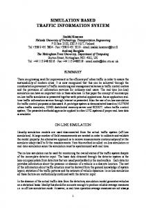
The first step builds a representation of the vorticity field over the grid, based on the vorticity information carried by the particles. Fig. 1 shows the vorticity interpolation scheme. V3
V4 A2
A1 Vp
A4 V1
A3 V2
Fig. 1. Vorticity interpolation.
The particle vorticities are accumulated on the grid in such a way that each particle contributes to the four grid points that surround it. The particle vorticity Vp is bilinearly interpolated to the grid points V1 to V4. For Vi (1 < i < 4) we have: A Vi = 2i Vp (11) h where A1 to A4 are the areas subtended by the particle and the grid points and h is the grid spacing. This scheme conserves the total vorticity of the system. With the vorticity grid at hand, the Poisson equation (9) is now solved relative to the stream function y(x,y) on a rectangular domain a £ x £ b, c £ y £ d. On the edges of this domain, boundary conditions must be imposed in order to have a complete formulation of the problem. A simple condition specifies that y(x,y) be equal to zero for x = a, x = b, y = c and y = d. This condition, coupled with the definition of the flow (10), implies that v(x,t) can only have a tangential component along the boundaries. No inflow or outflow is possible and the fluid remains constrained inside
the computational domain. The Laplacian operator in (9) is approximated with finite differences in order to solve the equation. The FISHPACK* library was used, containing a set of FORTRAN routines to solve both Poisson and Helmholtz type equations over a variety of coordinate frames [20]. At this point we have a discrete representation yi,j of the stream function over the grid. From this representation, the fluid's velocity field vi,j can be obtained. For a given grid point (i,j) the curl (10) is approximated by the following differences: vix, j =
y i , j +1 - y i , j -1 2h
, viy, j =
y i -1, j - y i +1, j 2h
(12)
A particle's velocity is now calculated with an interpolation scheme similar to the one previously used to interpolate vorticities. Considering again Fig. 1, where the grid points now store the velocities v1 to v4, the velocity vp of the particle is calculated through a bilinear interpolation: (13) v p = ( A1v1 + A2 v 2 + A3v 3 + A4 v 4 ) h 2 During the advection stage, each particle is displaced according to: x p ( t + Dt ) = x p ( t ) + v p ( t ) Dt
(14)
where Dt represents the time increment. Equation (14) can be easily identified with the Euler method for the solution of ordinary differential equations. More robust methods, like the Runge-Kutta, could have been used, with increased computational costs. Up to now the viscous effects, represented by the right hand side of the vorticity transport equation (7), have been neglected. Equation (14) updates the position of the particles but their vorticity remains constant, resulting in the simulation of an inviscid fluid. To simulate viscous diffusion of vorticity into the environment a simple random walk procedure can be used after the advection stage of each particle [5]. The advection of a particle p is now: x p ( t + Dt ) = x p ( t ) + v p ( t ) Dt + dx (15) where dx is a vector whose components (dx1,dx2) are independent gaussian variables with zero mean and variance 2 uDt . The random walk simulates the diffusion of vorticity in a statistical sense. Although the vorticity of each particle remains concentrated around the particle's centre, the particles themselves suffer a diffusion process which effectively spreads the vorticity field according to equation (7).
5 A Turbulent Jet Stream The vorticity model, described in the previous section, will be applied to the animation of gaseous phenomena. In particular, we wish to animate a column of smoke rising through the air. This type of animation can be used to simulate cigarette *
This library is part of the NetLib archive, available world-wide through anonymous FTP.
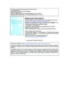
smoke. The combustion process occurring at the tip of the cigarette heats the air around it. Hot air, having lower density than ambient air, will rise until its thermal energy is dissipated through convection. At the same time, small ash particles are released from the cigarette tip and transported along with the rising jet. These particles are opaque and give a visual representation of the flow, which otherwise would have been invisible to the naked eye. To avoid performing a full-scale physical simulation of the phenomenon, the model of a mechanical jet will be used as an approximation to the behaviour of the much more complex thermal jet. In the mechanical jet, the heating and convection considerations are ignored. This amounts to dropping the variables of heat and density and retaining only the fundamental variables of the vorticity model, namely the vorticity and the stream function. The upward motion of the smoke will be imposed with a uniform vector field. Vortices are automatically created at the cigarette tip and will follow this uniform flow while interacting with each other. This situation is depicted in Fig. 2 and corresponds to a jet of fluid ensuing from an orifice of width W with a constant speed U0. U0 Unstable Laminar Flow Schematic of Physical Flow
y x W Fig. 2. A turbulent jet with upward velocity U0 and width W. The two dots represent two fluid particles and their respective circulations at the separation of the flow.
If we ignore for a moment any bulk rotational motion of the fluid we will have a uniform flow inside the region -W/2 < x < W/2 with upward speed U0 and outside of this region the fluid will remain at rest. There are two interfaces at x = -W/2 and x = W/2 where the two masses of fluid slide through each other. The vorticity is zero everywhere except at the interfaces where it is uniformly distributed along the height. For the interface at x = -W/2 the vorticity is positive, corresponding to a counterclockwise sense of rotation of the fluid. Reversibly, any fluid point lying along the line x = W/2 will have negative vorticity and will tend to spin in a clockwise manner. What we have then are two parallel vortex sheets with opposite vorticity. This scenario is mathematically possible but it is also completely unstable from a physical point of view. Abernathy has shown that tiny disturbances in the two sheets will quickly develop into a stable pattern, consisting of a succession of pairs of large
counter-rotating eddies [1]. This type of pattern arises in a wide variety of flow situations and is known as the Karman vortex street. The intrinsic instability of the two vortex sheets is quite pronounced. In our algorithm, errors due to finite approximations are sufficient to trigger the formation of the Karman street. Vorticity is continually created at the two points x = ±W/2, y = 0 at a constant rate given by: dG 1 = ± U 02 (16) dt 2 where the positive value refers to the left point. The variable G is called circulation and is related to the vorticity by the relation:
G = òò w dxdy
(17)
According to (16), as more fluid is ejected the total circulation and the total vorticity of the system increase steadily. The quadratic rate of increase relative to the ejection speed U0 makes the system very sensitive to this parameter. The vorticity created at the two exit points of the jet then travels upward with speed U0/2. This value comes from the fact that the vorticity lies in the interface between two masses of fluid travelling at speeds of 0 and U0 so that it will tend to have an average speed of U0/2. This uniform vertical flow is superposed over the rotational flow given by (10). To discretize the model of the turbulent jet, the continuous vorticity filaments which are shed at the exit points must be replaced by a sequence of vortex particles. The algorithm consists of iterating over the consecutive time instants ti = i.Dt for i Î N0. At the start of each iteration every particle is displaced vertically by an amount U0Dt/2 and a new pair of vortex particles is placed at the exit points, with circulations given by: gDt 2 Gi = ± U0 (18) 2 where the additional parameter g gives an animator control over the vorticity creation mechanism. It can be shown that the finite difference approximations, present in the Eulerian part of the algorithm, are responsible for the introduction of an artificial viscosity term, which has the effect of spreading the vorticity of a particle around its position [11]. The exact expression for this spreading effect is rather complicated and for simplicity reasons we will assume that the vorticity is uniformly distributed inside a circle whose radius we know to be proportional to the grid cell size h. With the above said and using (17) one gets: Gi µ h 2 w i (19) This equation is then plugged into (18) to arrive at a formula giving the vorticities wi of newly created particles. Notice that the constant of proportionality implicit in (19) can be hidden inside the g parameter.
6 Rendering Having the means to generate the time evolution of the jet stream, we must now turn to the question of how to visualise it. As previously said, the microscopic ash particles released from the cigarette and transported by the flow are responsible for the visible properties of the smoke. It seems natural to use particle elements again for rendering purposes. Such particles will act as fluid markers, being advected by the flow according to the advection equation (15), and will be passed on to the rendering module. At the start of every iteration and at the same time as new vortex particles are created, the span -W/2 £ x £ W/2, y = 0 (refer to Fig. 2) is filled with equispaced markers. All previously existing markers have been advected upwards by the flow so that a continuous stream is created at the origin. The creation process is controlled by a concentration parameter, measured in number of particles per grid cell, which determines the spacing and the amount of markers introduced. The random walk component of equation (15), induced by the viscosity of the fluid, has a jittering effect and prevents the occurrence of visual artefacts in the particle stream. Fluid markers are renderend using spot noise. For a more detailed explanation of this technique refer to [22].
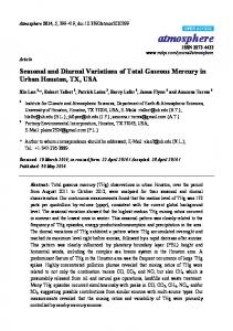
7 Results Colour plate 1 (see Appendix) shows frames from an animation of a turbulent smoke jet produced over a grid of 32´128 resolution, spanning an area of 0.25´1.0 spatial units. The jet has an initial width of 0.015625 (equivalent to a span of two grid cells) and initial velocity U0 = 0.5. The dynamics of vorticity is controlled by a factor g = 0.2 and the viscosity is u = 1.5´10-5. The jet has a concentration of about eight particles per grid cell for an image of 128´512 pixels. Particles are automatically deleted from the system when they hit the upper limit of the computational domain. This animation illustrates the transition from laminar to turbulent flow. The jet has an initial uniform upwards flow but the instability of the vortex sheet model soon manifests and the flow evolves into a complex pattern of turbulent eddies. This onset of turbulence is an example of how the macroscopic motion of the fluid can influence its microscopic motion (a uniform flow generates large eddies which decompose into smaller and smaller eddies). The computation times were measured on a Silicon Graphics Indigo 2 machine. The frame with the highest number of particles took 3.6 seconds to generate (0.43s for the solution of the Poisson equation, 2.29s for particle advection and field interpolations and 0.88s for rendering) for a total of 19676 particles (1905 vortex particles and 17771 fluid markers). Colour plate 2 (see Appendix) shows another animation of the same jet, this time with a width of 0.078125 (spanning 10 grid cells). The system reached a peak value of 64769 particles with a peak time of 11.89s per image.
The time complexity of the algorithm is O(k) + O(mn.log n) for a system with k particles and an m´n grid. The algorithm can be quite efficient, even for large numbers of particles, provided the grid resolution is kept small (typical values are between 32 and 256 cells along each side of the grid). The O(k) complexity on the number of particles is quite remarkable since previous particle dynamics algorithms had O(k2) or O(k.log k) [3]. This complexity is independent of the distribution of particles throughout the domain. To the authors knowledge, the only other particle algorithm with O(k) complexity is based on a multipole expansion of the inter-particle interactions [9].
8 Future Developments Many improvements can be made on the algorithm. The first and most obvious one is the extension to a fully three-dimensional vorticity model. In three dimensions, the concept of a vortex particle as the basic building block of the vorticity field must be replaced by the concept of a vortex filament; a thin, closed line, carrying a constant amount of circulation. A term must also be added to the right side of the vorticity transport equation (6) to account for a new phenomenon, known as vortex stretching [17]. Because of the orthogonality properties already explained in section 3, the vortex stretching term vanishes in two dimensions. During the evolution of the flow, vortex filaments tend to stretch and to become highly entangled in each other as a result of the vortex stretching mechanism. An initially smooth filament may end up having sections with high radius of curvature. These effects are a manifestation of the turbulent properties of the flow. In a discrete model of three-dimensional vorticity, a vortex filament must be represented with a collection of points, linked together with straight line segments or other higher order interpolants. As the filaments stretch and distort intermediate points must be inserted in the collection to keep a good accuracy of the representation [2]. Such a threedimensional vorticity algorithm will be harder to implement and will certainly be much slower. It is questionable whether such an algorithm can be useful for computer animation purposes. An interaction of the jet with an externally supplied wind field could also be modelled. At present the environment is considered to be at rest, which is not a very realistic assumption. The smoke stream would look more natural if small wind drafts could introduce disturbances in the flow. Along the same lines, the source of fluid should be able to move during the animation. Such an effect would cause a bending of the smoke stream in a direction opposite to the movement of the source. Another interesting possibility is the interaction of the fluid with rigid bodies. The fluid should be able to detect the presence of other bodies and adapt itself to avoid interpenetrations. In practical terms this would imply the specification of interior boundary conditions to the equation of the flow (9). The presence of viscous effects would vastly complicate this situation because a boundary layer and a vorticity creation mechanism would have to be considered along the surface of the objects [18]. In the opposite direction, the fluid should be able to influence the movement of
the rigid bodies through the actuation of drag and lift forces. These two mechanisms would allow fluid dynamics algorithms to be integrated in a transparent manner with already existing rigid body dynamics algorithms.
9 Conclusions We have presented a method for the simulation of turbulent behaviour in fluids. The method is based on computational techniques, well established in the CFD domain for some decades. We have taken some applications of fluid dynamics out of the realm of large vector supercomputers and have made them usable for medium sized workstations, where they may find application in computer graphics. All the control variables of the model can be conveniently abstracted so that any animator, with no prior knowledge of fluid mechanics, can rapidly take advantage of it. For the animation of smoke, for instance, one only has to specify simple parameters like the concentration of particles, the thickness and initial velocity of the smoke or the desired degree of turbulence. The algorithm is stable. The vorticity of a particle is uniformly distributed inside a circle centred at the particle's position. The radius of the circle is a function of the grid spacing and the quantification errors made by the finite difference approximations. This fuzziness of the particle's vorticity makes the interaction force between particle pairs go smoothly to zero for short ranges. The possibility of hard collisions is avoided and the total energy of the system can be efficiently conserved. The algorithm is fast since its complexity changes linearly with the number of particles. We have produced animation sequences using large numbers of particles, which would have been impracticable or even impossible to produce with previous particle dynamics algorithms. The algorithm is also easy to implement. Apart from the Poisson equation solver, which can be implemented with public domain software, all other operations consist of trivial bilinear interpolations and particle advections. The main disadvantage of the method lies in its two-dimensional nature. It produces animated textures which later can be mapped onto three-dimensional objects. Threedimensional algorithms are possible and several implementations already exist. However, the increased complexity of three-dimensional vorticity models reflects on both the complexity and the computational costs of these algorithms. In this article the vortex particle method was applied to the animation of a turbulent smoke stream but many other applications of the same basic algorithm can be devised. Several animations are currently under development, namely the animation of turbulent planetary atmospheres (along the lines of [23]), the generation of wakes behind moving bodies and the simulation of foam on the surface of water streams. Acknowledgements The authors wish to express their gratitude to Joaquim Jorge for reviewing the text and to Gavin Pringle for helpful criticisms along the way. The first author would also like to thank
Mafalda Barbosa for showing an incredible amount of patience at a time when other more urgent work was needing immediate attention.
References 1. Abernathy, F.H., Kronauer, R.E., "The formation of vortex streets", Journal of Fluid Mechanics, vol. 13, pp. 1-20, 1962. 2. Almgren, A.S., Buttke, T., Colella, P., "A Fast Adaptive Vortex Method in Three Dimensions", Journal of Computational Physics, vol. 113, pp. 177-200, 1994. 3. Appel, A.A., "An Efficient Program for Many-Body Simulations", SIAM Journal on Scientific and Statistical Computing, vol. 16, n. 1, pp. 85-103, 1985. 4. Chiba, N., Muraoka, K., Takahashi, H., Miura, M., "Two-dimensional Visual Simulation of Flames, Smoke and the Spread of Fire", The Journal of Visualisation And Computer Animation, vol. 5, pp. 37-53, 1994. 5. Chorin, A.J., "Numerical Study of Slightly Viscous Flow", Journal of Fluid Mechanics, vol. 57, n. 4, pp. 785-796, 1973. 6. Christiansen, J.P., "Numerical Simulation by the Method of Point Vortices", Journal of Computational Physics, vol. 13, pp. 363-379, 1973. 7. Ebert, D.S., Parent, R.E., "Rendering And Animation of Gaseous Phenomena by Combining Fast Volume and Scanline A-buffer Techniques", ACM Computer Graphics, vol. 24, n. 4, pp. 357-366, (Proc. SIGGRAPH '90). 8. Gardner, G.Y., "Visual Simulation of Clouds", ACM Computer Graphics, vol. 19, n. 3, pp. 297-363, (Proc. SIGGRAPH '85). 9. Greengard, L., Rokhlin, V., "A Fast Algorithm for Particle Simulations", Journal of Computational Physics, vol. 73, pp. 325-348, 1987. 10. Haumann, D., Wejchert, J., Arya, K., Bacon, B., Khorasani, A., Norton, A., Sweeney, P., "Aspects of Motion Design for Physically-Based Animation", Scientific Visualisation of Physical Phenomena, (CG International '91 Proceedings), Springer-Verlag, Tokyo, June 1991, pp. 147-158. 11. Hockney, R.W., Eastwood, J.W., "Computer Simulation Using Particles", IOP Publishing, Bristol, 1988. 12. Leonard, A., "Vortex Methods for Flow Simulation", Journal of Computational Physics, vol. 37, pp. 289-335, 1980. 13. Perlin, K., "An Image Synthesiser", ACM Computer Graphics, vol. 19, n. 3, pp. 287-296, (Proc. SIGGRAPH '85). 14. Reeves, W.T., "Particle Systems- A Technique for Modelling a Class of Fuzzy Objects", ACM Computer Graphics, vol. 17, n. 3, pp. 359-376, (Proc. SIGGRAPH '83).
15. Sakas, G., "Modelling and animating turbulent gaseous phenomena using spectral synthesis", The Visual Computer, vol. 9, n. 4, pp. 200-212, 1993. 16. Saupe, D., Peitgen, H.O., "The Science of Fractal Images", Springer-Verlag, Berlin Heidelberg New York, 1988. 17. Sethian, J., "A Brief Overview of Vortex Methods", Vortex Methods and Vortex Motion, Gustafson, K.E., Sethian, J., (Eds.), SIAM, 1990 18. Sethian, J., Brunet, J., Greenberg, A., Mesirov, J.P., "Two-Dimensional, Viscous, Incompressible Flow in Complex Geometries on a Massively Parallel Processor, Journal of Computational Physics, vol. 101, pp. 185-206, 1992 19. Stam, J., Fiume, E., "Turbulent Wind Fields for Gaseous Phenomena", ACM Computer Graphics, vol. 27, n. 4, pp. 369-376, (Proc. SIGGRAPH ´93). 20. Swarztrauber, P., Sweet, R., "Efficient Fortran SubPrograms For The Solution Of Elliptic Equations", NCAR TN/IA-109, July, 1975, 138 pp. 21. Tennekes, H., Lumley, J., "A First Course in Turbulence", MIT Press, Cambridge, 1972. 22. van Wijk, J.J., "Flow Visualisation with Surface Particles", IEEE Computer Graphics & Applications, pp. 18-24, July, 1993. 23. Yaeger, L., Upson, C., Meyers, R., "Combining Physical and Visual Simulation: Creation of the Planet Jupiter for the Film 2010", ACM Computer Graphics, vol. 20, n. 4, pp. 85-93, (Proc. SIGGRAPH '86).
Two-dimensional simulation of gaseous phenomena using vortex particles
Colour Plate 1. Turbulent smoke stream.
Colour Plate 2. Turbulent smoke stream with increased thickness.