automation is illustrated in a case study of an Automated. Teller Machine (ATM) System. The UCDA tool increases design productivity, reduces time-to-market ...
1
UCDA: Use Case Driven Development Assistant Tool for Class Model Generation Kalaivani Subramaniam, Dong Liu, Behrouz H. Far and Armin Eberlein Department of Electrical and Computer Engineering, University of Calgary 2500, University Drive, N.W., Calgary, Alberta, Canada, T2N 1N4 {subrama, liud, far, eberlein}@enel.ucalgary.ca Abstract. The development of class models using the Rational Unified Process (RUP) requires complete, correct and unambiguous use case specification documents. The Use Case Driven Development Assistant (UCDA) tool provides automated assistance in developing use case diagrams, writing use case specification documents and developing the analysis class models. UCDA uses a freely available natural language parser and Rational Rose’s extensibility interface to support the automation of the Object Model Creation Process (OMCP). The parser is a shift-reduce parser and is implemented in Python. This paper introduces the UCDA tool and its application in OMCP. The process of automation is illustrated in a case study of an Automated Teller Machine (ATM) System. The UCDA tool increases design productivity, reduces time-to-market and is of great help to novice software developers.
1. Introduction Object Oriented Analysis and Design (OOAD) is a software development paradigm widely used in software development. Identifying objects and classes from requirements [8] that are represented in natural language is an essential task in OOAD. UCDA employs common requirements elicitation techniques to gather requirements and to document them in the requirements document. The software designer then analyzes the requirements and identifies the objects with the Object Model Creation Process (OMCP) [4]. Attributes, associations and behaviour of objects are also established as part of this model. Later, the object model is refined using generalization, and objects and classes are identified based on domain knowledge, real world experiences and user interviews. Tools that implement this process are already available [4]. NIBA (Natural Language Requirements Analysis) is an approach that starts with linguistic analysis and transforms a textual requirements specification into a conceptual predesign schema, which is then validated and mapped onto conceptual schema [1]. This tool parses the
requirements in German. The tool LInguistic Assistant for Domain Analysis (LIDA) processes text to develop object models. It analyzes the text to identify the model elements; then the model elements are refined through a validation process [2]. Our methodology follows the IBM Rational Unified Process (RUP) approach to automate the class model generation. “RUP is a configurable software development process platform that delivers proven best practices and a configurable architecture” [3]. RUP implements several best practices in software engineering. It specifies the functional behaviour of a system using use cases. Use case model development is a kind of knowledge elicitation. The structure of this paper is as follows. Section 2 provides a methodology for developing the class model. Section 3 describes UCDA, a tool that is designed to generate the use case model, robustness diagrams, collaboration diagrams and class diagrams. Section 4 presents a case study of the proposed system. Finally, Section 5 provides conclusions.
2. Methodology Our methodology requires a careful analysis of the stakeholders’ requests, which are stated in textual form. Use cases and classes are then identified based on predefined rules. The method follows the Rational Unified Process (RUP) approach to develop the use case model and the class model. The models are developed using Rational Rose according to the Unified Modeling Language (UML) standards. The process starts with stakeholders’ requests of the proposed system. Typically these requests are parsed by the natural language parser and then analyzed by the system to identify actors and use cases. The relationships among actors and use cases are identified and the use case diagram is developed using these artifacts. Detailed information about each use case is collected from the stakeholders. This information is formalized according to a use case template, validated and collected in a use case
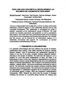
2 specification document. The document along with the use case diagram serves as the source of information for developing the class diagram. The objects are identified from the use case specification document and categorized into boundary objects, entity objects or control objects. The robustness diagrams are developed to show the different types of objects and their relationships to one another. Then the collaboration diagrams are generated to show the messages passed between the objects. A glossary is used during this process to prevent ambiguity and increase consistency. Finally objects are refined to generate the class diagram. The activity diagram showing the workflow of the UCDA tool is shown in Fig.1. An example of using this methodology is given in Section 4.
• • • • • • • • •
Identify A c tors and Us e Cas es from S tak eholders ' reques ts
Recognises certain complex sentences and simplifies them. Identifies actors and use cases and develops use case diagrams. Generates XML files containing the details of the models. Generates the models in Rational Rose. Assists the user with filling in the use case specification template. Validates the use case specification document. Reads the use case specification to identify objects and their associations; and develops robustness diagrams. Identifies messages passed between objects and develops collaboration diagrams. Generates and validates the class model.
3.2. Architecture The architecture of UCDA is shown in Fig. 2.
Develop Us e Cas e diagram and Us e Cas e S pec ific ation NATURAL LANGUAGE PARSER
Identify objec ts and de velop Robus tnes s diagram Identify A s s oc iations am ong objec ts and develop Collaboration diagram
STAKEHOLDERS' REQUESTS
USE CASE MODEL DEVELOPER GLOSSARY
BUSINESS RULES
Refine objec ts and develop c las s diagram
USE CASE SPECIFICATION
CLASS MODEL DEVELOPER
CLASS DIAGRAM
GLOSSARY
BUSINESS RULES
Fig. 2 Architecture of UCDA Fig. 1 The workflow of UCDA tool
3. UCDA: Use Case driven Development Assistant 3.1. Overview UCDA (Use Case driven Development Assistant) is a tool that helps developers to develop use case models, robustness diagrams, collaboration diagrams and class diagrams; and to visualize these models using the Rational Rose tool. UCDA supports the UML standards. A freely available natural language parser is integrated with UCDA tool to parse stakeholder requests. The various guidelines to extract the actors, use cases, objects and classes are applied to the parser output. UCDA has the following features. It: • Uses a natural language parser to parse stakeholder requests. Basically the parser analyzes the sentence and tags each word with its part-of-speech.
UCDA consists of two main components: The Use Case model developer and the Class model developer. The use case model developer helps the stakeholder to specify the requirements of the proposed system and to identify actors and use cases. These actors and use cases can be exported to the modeling tool. The modeling tool used in the UCDA tool is Rational Rose. The changes made to the model in Rational Rose affects the elements in UCDA tool. Use cases can be realized by the Class model developer. Objects and messages between them are identified from the use case specifications. The tool can generate robustness diagrams and collaboration diagrams in Rational Rose. The behaviour described in use case specifications can be distributed to the analysis classes. The analysis class model is the final output of the tool.
3.3. Use Case Model Developer The various features of use case model developer component are:
3 •
Read text entered by stakeholder and assign part-ofspeech to words in the text. • Study the structure of the sentence and check if it is a complex sentence (e.g., sentences with more than one verbs or sentences with conjunctions) • If the sentence is complex, reduce the complexity by splitting it into simpler sentences. • Retrieve the subject and predicate from the simple sentences. • Identify the modifiers (e.g., adjectives, auxiliary verbs) associated with the subject and predicate. • Filter the modifiers and check if subject exists in the glossary. If subject exists then subject is the actor and predicate is the use case. Kurt Bittner and Ian Spence provide a questionnaire to identify actors and use cases [5]. In UCDA, the structure of the sentence is considered for automating actor and use case identification. The following rules are applied for automating actor and use case identification. 1. If the Subject of a sentence is a noun or noun phrase consisting only of nouns, and this noun/noun phrase is found in the glossary then the noun/noun phrase is an actor. 2. If system is the Subject of the sentence, then it is not a valid actor. 3. If the Subject of a sentence is an actor, then the following predicate (P) forms are valid use cases. P: V; P: V/NP; P: V/PP 4. If the Subject of a sentence is an actor and the predicate is of the form: P: VP/NP1/“from”/NP2 then VP/NP1 is the use case and NP2 is an actor and an association exists from the actor to the use case. 5. If the Subject of a sentence is an actor and the predicate is of the form: P: VP/NP1/”to”/NP2 then VP/NP1 is the use case and NP2 is an actor and an association exists from an actor to the use case. V: Verb; NP: Noun Phrase; PP: Prepositional Phrase The next task of the use case model developer component is to generate the use case specification document. Each use case is associated with a use case specification document. UCDA provides the interface for the user to enter use case specification details according to the use case specification template (shown in Table 1). Table 1. Use Case Specification template 1. 2.
3. 4. 5. 6.
Use Case Name 1.1 Brief description Flow of Events 2.1 Basic Flow 2.2 Alternative Flow Special Requirements Preconditions Post conditions Extension Points
This document is parsed by the class model developer component to identify objects. So the statement structures should be simple (shown in Fig. 3).
VP: Verb Phrase NP: Noun Phrase Vgp: Verb Group AP: Adjective Phrase PP: Prepositional Phrase
ch oice se qu en ce
Fig. 3 Possible statement structures UCDA verifies that the statements entered by the user conform to the above statement structures. Conditional statements start with an IF statement, iterative statements with a WHILE statement and concurrency statements with a CON statement. Pronouns are replaced by concrete nouns and Passive voice is reconstructed to be active. The tool verifies the document based on completeness, complexity and structure.
3.4. Class Model Developer To develop the class model from the use case specifications, we summarized the relationships between syntactic structures of natural language and semantic associations of objects in the models. Fig. 4 shows a model of the actions in actor-system interaction [6]. Four types of behaviour are included in the model. The relationships between the behaviour types and the associations of stereotype objects are listed in Table 2.
4
Behavior Types:
Request Validation
Actor
Request Validation Change Response
Change
Response
System
Fig. 4 An actor-system interaction model Table 2. Relationships between behaviour types and associations between stereotype objects Behaviour Type Association Request Validation Change Response
: actor, object
and
: boundary object,
: control object,
: entity
We identified the relationships between all statement structures and behaviour types, and represented them in 17 rules for object and message identification [7]. Because of the length of this paper, we only demonstrate one rule for transitive structure shown in Fig. 5, where NP represents a noun phrase; VPss represents a verb phrase with the statement structure; PP represents a prepositional phrase; Vgp represents a verb group; and Prep represents a preposition.
The responsibilities of the classes can be identified from the messages in the collaboration diagrams. Each message consists of a sender, a receiver, and an action. The receiver has the responsibility for the execution of the action. The messages in collaboration diagrams are transformed to the classes’ responsibilities in this way. Composition, generalization and aggregation relationships are to be identified in the class model of the system under development. Rule: If one use case includes another use case, then a composition relationship is likely to exist between the core control classes identified from the use cases. Rule: If one use case has a generalization relationship with another use case, then a generalization relationship is likely to also exist between the core control classes identified from the use cases. We propose a method to validate the analysis model, especially the robustness diagrams. There are some constraints for objects and associations in a robustness diagram according to its semantics. The rules listed in Table 3 are derived from the constraints and used for robustness diagram validation. Table 3. Rules for robustness diagram validation Case
NP
Allowed Not allowed.
Vgp
Not allowed.
Predicate VPss
Suggestion
Not allowed.
Statement Subject
Validation
Not allowed.
PP NP Prep
Allowed.
NP
Not allowed.
Fig. 5 The structure of a transitive statement The rule for object identification is: Rule: If the structure of a statement is transitive (as shown in Fig. 3), and Subject/NP//Noun(head) is an actor, then this statement corresponds to the Request behaviour type. Predicate/PP/NP//Noun(head) is a boundary object if it exists in the glossary, and Predicate/VPss/NP/ Noun(head) is an entity object if it exists in the glossary. If there are two objects or an actor and an object in one statement, an association between them is identified. To generate the collaboration diagram, the messages contained in one scenario are identified. The corresponding rule for message identification is: Rule: If Subject/NP//Noun(head) is an actor, and Predicate/PP/NP//Noun(head) is a boundary object, then the action is Predication/VPss/Vgp/Verb(head) + Predication/VPss/Vgp/NP//Noun(head), the sender is Subject/NP//Noun(head) and the receiver is Predicate/PP /NP//Noun(head).
Allowed. Allowed. Not allowed.
: actor, object
: boundary object,
: control object,
: entity
4. UCDA: Case Study This section uses the ATM system specification to show the working of the proposed system. The functional description of an ATM system is: “The customer inserts the cash card in the machine. Customer can withdraw cash from an account. The bank approves the transaction. In addition, customer can deposit the amount. Customer can transfer amount between accounts. Customers can check the balance in
5 the account. The customer can cancel the transaction at any time.” The natural language parser parses the specification. Based on the rules given in Section 3.3, the system identifies the actors and use cases, and generates an XML file containing actors and use cases. The tool reads the XML file and generates the corresponding diagrams in the Rational Rose tool. The use case diagram generated by the UCDA tool is shown in Fig. 6. The association between actors and use cases are shown in use case diagram. Fig. 7 Use Case Specification Interface Screen Actors: customer, bank Flow of Events: Basic Flow: 1. the system start withdrawal transaction; 2. the customer select the account on the customer console; 3. the system get the account from the customer console; 4. the customer select the amount on the customer console; 5. the system get the amount from the customer console; 6. the system generate the withdrawal transaction information; 7. the system send the withdrawal transaction information to the bank; 8. the bank send the withdrawal transaction approval to the system; 9. the system dispense the cash in the cash dispenser; 10. the customer get the cash from the cash dispenser; 11. the system record the withdrawal transaction information into the log; 12. the withdrawal transaction end; Alternative Flow: If the bank do not approve the withdrawal transaction, then 1. the system display an error message on the customer console; 2. the system record the withdrawal transaction information into the log; 3. the withdrawal transaction end;
Fig. 6 Use Case diagram generated by UCDA We compared the use case diagram generated by the tool with that of software engineering graduate students having considerable knowledge in this area. The tool is evaluated based on the time taken to develop the use case diagram and the number of correct actors and use cases identified. The tool generates the use case diagram much faster compared to students and the number of correct actors and use cases generated by the tool are also higher. We also compared the use case diagram generated by the tool with the use case diagram provided by experts. We found that the tool has identified 100% of the actors and 70% of the use cases. To complete the use case model, each use case is associated with a use case specification document. Fig. 7 shows the user interface for writing use case specification details. The tool provides the template to document conditional, iterative and concurrent statements. The tool verifies the sentences entered by the user according to the format specified in Fig. 3. The tool generates the document in word format and XML format. The use case specification document for the “withdraw cash” use case is specified in Fig. 8. The CREWS project suggests several guidelines for writing the use case specification document [9]. Our tool implements these guidelines and templates.
Fig. 8 Use Case Specification of ‘withdraw cash’ The specification is processed using the methodology discussed in Section 3.4. Fig. 9 shows the environment for use case realization including Rational Rose.
. Fig. 9 The environment for use case realization Fig. 10 shows the robustness diagram that is generated from the use case specification. The validation of the robustness diagram shows that there should be a boundary object between the bank and the Withdrawal transaction class. The use case specification is reviewed and steps 7 and 8 in the basic flow are revised as follows: 7. the system send the withdrawal transaction information to the network connection;
6 8. the bank get the withdrawal transaction information from the network connection; 9. the bank send the withdrawal transaction approval to the network connection; 10. the system get the withdrawal transaction approval from the network connection; A new robustness diagram is generated according to the revised use case specification and shown in Fig. 11.
Network connection send withdrawal transaction information() send withdrawal transaction approval()
Cash dispenser
Log
dispense cash()
record withdrawal transaction information()
Withdrawal transaction start() get account() get amount() generate withdrawal transaction information() get withdrawal transaction approval() end()
Customer console select account() select amount() display error message()
Customer
Bank
Customer console Withdrawal transaction (from Logical View)
(from Use Case View)
(from Logical View)
(from Use Case View)
Fig. 13 Class diagram
Log
Cash dispenser
(from Logical View)
(from Logical View)
Fig. 10 Robustness diagram
Customer (from Use Case View)
Customer console Withdrawal transaction (from Logical View)
Bank
Network connection (from Logical View)
(from Logical View)
(from Use Case View)
We compared the performance of the tool with the software engineering student’s performance provided the student already knows about OOAD. We found that the tool generates the better class model in less time compared to the students. By automating these tasks, software design effort and cost can be reduced. Furthermore, this tool provides valuable guidance to novice software designers.
References Cash dispenser (from Logical View)
Log (from Logical View)
Fig. 11 New Robustness diagram The collaboration diagram is shown in Fig. 12, and the class diagram containing the identified classes from the use case is shown in Fig. 13. All the diagrams are automatically generated by UCDA. 1: start 6: generate withdrawal transaction information 14: end 17: end
2: select account 4: select amount
3: get account 5: get amount
: Customer console
: Customer
13: record withdrawal transaction information 16: record withdrawal transaction information
15: display error message : Withdrawal transaction
: Log
7: send withdrawal transaction information 11: dispense cash 10: get withdrawal transaction approval
12: get cash
8: get withdrawal transaction information
: Cash dispenser
9: send withdrawal transaction approval : Network connection : Bank
Fig. 12 Collaboration diagram
5.
Conclusion
Identifying objects and classes is a challenging task in software engineering. In this paper, we presented a methodology to develop a class model from natural language requirements and its implementation in the UCDA tool. The methodology focuses on generating intermediate artifacts such as use case diagrams, robustness diagrams and collaboration diagrams.
[1] L.C. Niba, “The NIBA Workflow: From textual requirements specification to UML-schemata”, Proceedings of International Conference on Software & Systems Engineering and their Applications, ICSSEA 2002, Paris, December 2002. [2] Scott P. Overmyer, Benoit Lavoie, Owen Rambow, “Conceptual Modeling through Linguistic Analysis Using LIDA”, Proceedings of the 23rd International Conference on Software Engineering, ICSE 2001, 401-410, May 2001, Toronto, Ontario, Canada. [3] Rational Unified Process http://www-306.ibm.com/software/awdtools/rup/ [4] Romi S. Wahono, Behrouz H. Far, Jingde Cheng, “A Framework of Object Identification and Refinement Process in Object-Oriented Analysis and Design”, Proceedings of the 1st IEEE International Conference on Cognitive Informatics, ICCI 2002, Calgary, Canada, 2002. [5] Kurt Bittner, Ian Spence, “Use Case Modeling”, Addison Wesley, 2002. [6] Alistair Cockburn, “Writing Effective Use Cases”, Addison-Wesley, 2000. [7] D. Liu, “Automating Transition from Use Cases to Class Model”, Master Thesis, University of Calgary, Calgary, 2003. [8] Grady Booch, “Object-Oriented Analysis and Design with Applications”, Addison-Wesley, 1994. [9] Karl Cox, Keith Phalp: “Use Case Authoring: Replicating the CREWS Guidelines Experiment”, Int. Journal of Empirical Software Engineering, Issue 5, 245-267, 2000.