reviewed paper Automated Urban Management Processes: Integrating a Graphical Editor for Modular DomainSpecific Languages into a 3D GIS Michel Krämer, Andreas Stein (Michel Krämer, Fraunhofer Institute for Computer Graphics IGD, Fraunhoferstraße 5, 64283 Darmstadt, Germany,
[email protected]) (Andreas Stein, Fraunhofer Institute for Computer Graphics IGD, Fraunhoferstraße 5, 64283 Darmstadt, Germany,
[email protected])
1 ABSTRACT In this paper we present the results of integrating a graphical editor for geospatial processing workflows into a 3D GIS. We use modular domain-specific languages (DSLs) that are tailored to specific application domains. The vocabulary consists of so-called recipes that are grouped into cookbooks representing the language for a certain application domain. Recipes can be reused in multiple cookbooks. This approach allows for a good usability as the user quickly becomes familiar with the domain-specific languages by recognizing common recipes. In this paper we also describe guidelines for choosing the right granularity for recipes which allows for complex rules while using simplest possible recipes. We also describe a workflow for domain-specific language design based on ontologies to identify the correct domain vocabulary. Our approach can be used to automate processing of geospatial datasets in the area of urban planning. To evaluate our approach we use the implemented graphical rule editor in a practical scenario and present it to a user group from the urbanAPI project. 2 INTRODUCTION Geospatial data is used in a wide range of applications. One of them is urban planning where spatial data is used for urban assessment or simulation of planning decisions as well as environmental and disaster management, etc. These applications often require the domain expert to integrate or harmonize data, to process it in order to derive new information, to use it as input for simulation algorithms, and finally, to visualize data in order to assess the results. Today these steps are mostly performed manually using standard GIS software. This can be quite tedious, especially if the planning scenario is complex and is subject to discussion—be it amongst urban planners and municipal decision makers or even in public. Discussion is inevitable in urban planning and of course a useful instrument to improve urban development. However, expectations of stakeholders often change through discussion. If this happens constantly, urban planners will likely have to process all the spatial data again and again. If they have to do that manually, new iterations will be rather lengthy and presumably expensive. Automated processes can help alleviate this problem. Today, the amount of spatial data to be analysed and processed grows continuously. For example, modern satellite imagery produces more data per day than it produced during several months a few years ago. There is a growing need to analyse this information for applications such as urban planning. For example, satellite images showing development over several years can be used to estimate or simulate urban growth. Searching LIDAR data for special geological formations can not only help assess areas for urban development but also recognise environmental risks such as landslides. The larger the data to analyse becomes, the more the domain expert depends on automated processes. One way to automate processes in today’s GIS software is to use scripts written in a general purpose language—for example Visual Basic or Python as seen in the proprietary software solution ESRI ArcGIS. On the other hand there are some products such as Safe Software FME Desktop that try to ease the process definition by using graphical elements such as diagrams or graphical workflow representations. However, in recent years another approach—which is actually well-known for quite some time in computer science—has become more and more prominent. In order to allow users with non-IT background to specify complex configurations, rules and workflows, so-called domain-specific languages (DSLs) are used. Such languages have a limited vocabulary that is tailored to specific application domains or even single use cases. DSLs allow the domain experts to express problems in their own words, in fact to program complex workflows without the need for a background in computer science or a deep understanding of programming. To summarize, for urban planning large amounts of data have to be processed over and over again. Current automation solutions use general purpose languages or other graphical representations that are quite complex, probably hard to understand for non-IT personnel and hence error-prone. Domain-specific Proceedings REAL CORP 2014 Tagungsband 21-23 May 2014,Vienna, Austria. http://www.corp.at
ISBN: 978-3-9503110-6-8 (CD-ROM); ISBN: 978-3-9503110-7-5 (Print) Editors: Manfred SCHRENK, Vasily V. POPOVICH, Peter ZEILE, Pietro ELISEI
99
Automated Urban Management Processes: Integrating a Graphical Editor for Modular Domain-Specific Languages into a 3D GIS
languages can help reduce the complexity of a specific problem to an application domain that is well-known to the user—i.e. the domain expert. In this paper we present the results of integrating a graphical editor for domain-specific languages into an existing 3D GIS. We use chainable production rules to allow the user to create sequential workflows. We describe the basic grammar for our languages and the UI elements we implemented. Finally, we evaluate if our solution can be used reasonably in a selected scenario. 3 STATE OF THE ART Domain-specific languages (DSLs) are languages with the following properties: •
They are tailored to a specific application domain or even to a single use case;
•
The language’s vocabulary contains words well known to the domain expert;
•
The language’s expressiveness is rather limited.
The latter means the language cannot be used for general purpose—that’s why it is indeed called a domainspecific language—but instead it is a lot easier to understand and to use for non-IT personnel. In computer science, domain-specific languages have been used for quite some time already. In the IETF protocol specifications, for example, DSLs are very often used to facilitate interoperability because they avoid machine-dependent minutiae such as encoding issues. Apart from that, in the UNIX operating system you can very often find DSLs in configuration files. For example, the Apache HTTP server configuration files are written in a special language using words from the domain of web server configuration—e.g. RewriteRule, Redirect, Proxy, etc. Furthermore, DSLs are also used in database management systems. SQL, for example, is in fact a domain-specific language. DSLs can be created in various ways. Martin Fowler gives a comprehensive overview over domain-specific language design (Fowler, 2010). He differentiates between internal DSLs and external ones. Internal DSLs are embedded into a host language, most often a general purpose language. External ones have their own custom syntax and grammar. Modern dynamic languages such as Groovy or Ruby allow developers to create internal DSLs very easily. In Groovy you can even alter the language’s syntax by building and traversing arbitrary abstract syntax trees (ASTs) with compiler plugins. Static languages often do not provide such means, but Scala, for example, is known to have been used already for a lot of internal DSLs. For example, Lee et al. developed the Delite Compiler Framework which uses a DSL embedded into Scala (Lee et al., 2011). Delite can be used to execute parallelized code on multiple platforms. The DSL abstracts the code from the actual platform it is executed on. Lee et al. use a technique called language virtualization (Chafi et al., 2010) which allows them to reuse existing Scala compiler components such as lexer, parser and type checker. Apart from that, you can also find embedded DSLs in Java. Albeit being restricted by the host language’s syntax so-called fluent interfaces have been widely adopted. Fluent interfaces are often referred to as being internal DSLs. Compared to internal DSLs, external ones are not restricted by the host language. With the right tool, the language designer is able to do almost anything. Just like general purpose languages, external DSLs are typically created using language recognition tools such as Lex/Yacc or ANTLR, but they can also be created with sophisticated language workbenches such as Xtext. Graphical DSLs use visual elements. They can be found in areas such business process modelling. For example, BPEL (Business process execution language) and XPDL (XML process definition language) are domain-specific languages defining the execution semantics of business processes. The MIT App Inventor is a tool that allows developers to create Apps for the Android operating system using graphical programming elements. However, App Inventor tries to mimic a general purpose language and therefore goes beyond the scope of typical a DSL. There are existing tools containing a graphical editor that can be used to specify geospatial operations. For example, with ESRI’s ArcGIS ModelBuilder (which is part of the ESRI’s ArcGIS Spatial Analyst) users can perform operations such as classification or colourisation on data that matches given criteria. The ArcGIS ModelBuilder is targeted to geospatial applications and therefore only contains operations needed in this domain. This includes spatial indexes (and operations such as “near” or “inside”) as well as geometrical operations (such as building buffer polygons). The tool supports 2D data and 2,5D raster data, but lacks support for higher dimensions. 3D city models are nowadays an integral part of the urban planning process.
100
REAL CORP 2014: PLAN IT SMART
Michel Krämer, Andreas Stein
Such kind of data cannot be processed with the ArcGIS ModelBuilder. The approach presented in this paper, however, can be applied to 3D data. The use of domain-specific languages in the area of urban planning is rather novel. In one of our previous papers we present a first approach of performing urban policy modelling and making with the help of ICT enabled tools, in particular domain-specific languages (Krämer et al., 2013). We use DSLs to define policy models that can be used during the planning phase, and also for automated evaluation of policy implementations later on. Compared to the approach in this paper, we use textual DSLs—instead of graphical ones—to define the policy model which makes it very readable and easy to understand for domain experts (i.e. urban planners). In order to specify automated workflows, however, we suggest using graphical DSLs consisting of simple conditions and processing steps tailored to the urban planning application domain. With the graphical editor presented in this paper, specifying a workflow is a matter of selecting the right conditional blocks and actions, putting them in the correct order and specifying some parameters if necessary. 4 LANGUAGE SPECIFICATION In our implementation geospatial processes are described using so-called production rules. They consist of two parts (cf. figure 1): •
The condition (or left-hand side) selects objects from the dataset. In our case, we essentially use a chain of filters here that is applied to the whole dataset. Objects that pass the filter chain will be selected.
•
The rule’s consequence (or action, or right-hand side) specifies what should be done with the selected objects. In our implementation you can use various pre-defined actions for data manipulation.
Production rules are event-based and can be chained. Executing a rule may alter the dataset. This might let the condition of another rule become true which will then be executed as well. This process is typically called forward chaining. It is an integral part of production rule systems which allows the user to create complex processing workflows.
Fig. 1: A production rule consists of a condition (left-hand side) and an action (right-hand side), both containing recipes (here symbolized with ‘R’). If the condition evaluates to true, the action will be executed.
In our implementation, rules are specified with pre-defined, reusable components that we call recipes. To improve usability we implemented so-called cookbooks which group recipes by the application they are used in. For example, our rule editor provides a number or recipes to assess data quality. All of them are kept in a cookbook called ‘Quality Assurance’. Basically, cookbooks represent different domain-specific languages. The ‘Quality Assurance’ cookbook, for example, represents the language that contains the vocabulary of the ‘quality assurance domain’ (cf. figure 2). Most of the recipes in this cookbook use terms specific to this domain, others are rather generic and can be reused in various domains. They are hence assigned to multiple cookbooks. This allows for a good usability as the user quickly becomes familiar with the individual domainspecific language vocabulary by recognizing common recipes.
Proceedings REAL CORP 2014 Tagungsband 21-23 May 2014,Vienna, Austria. http://www.corp.at
ISBN: 978-3-9503110-6-8 (CD-ROM); ISBN: 978-3-9503110-7-5 (Print) Editors: Manfred SCHRENK, Vasily V. POPOVICH, Peter ZEILE, Pietro ELISEI
101
Automated Urban Management Processes: Integrating a Graphical Editor for Modular Domain-Specific Languages into a 3D GIS
Fig. 2: Recipes (conditions and actions) are grouped into application-specific cookbooks. In this case, there is a cookbook containing recipes related to quality assurance and another one containing recipes for urban planning.
The recipes that can be used in a rule’s condition are functional filters without side-effects. This allows them to be used in arbitrary order. The recipes on the rule’s right-hand side are imperative actions that must be executed in the order specified since one recipe might depend on the results of another. In order to achieve good usability we designed our rule editor as follows: •
The recipes are intended to be self-explanatory for the domain experts. They use domain vocabulary and they do not expose too many technical details to the user.
•
The rule editor detects conflicting input and therefore helps users to create correct rules. For example, the rule editor disallows the user to append a recipe to a rule’s right-hand side if there is already a recipe that deletes the selected data. Any other recipe would be useless after that.
•
We have defined guidelines for granularity (see section 5) in order to enable complex rules while using simplest possible recipes.
Some of the recipes require additional information from the user. Hence the recipes can have parameters. For example, there is an action to extrude a plane from 2D to 3D which needs the user to specify the height. Our rule editor provides forms for the recipe parameters. 5 GRANULARITY In order to achieve a good usability we took special care to create recipes that are as simple as possible but at the same time as powerful as needed, so rules will be understandable for the domain expert and not too large (i.e. powerful). Condition recipes and action recipes should be categorized as follows: •
Location. Recipes from this category operate on the location of objects in the dataset. For example, the data source (web service, file, etc.), the layer the object is assigned to, and so on.
•
Property. This category contains recipes that operate on object attributes such as colour, texture, metadata, level of detail (LOD), object type, etc.
•
Geospatial. Recipes from this category are related to geospatial properties of objects in the dataset. For example, height, width and depth of an object, geospatial coordinates, etc.
Each recipe can only be assigned to one category. That means condition recipes cannot filter for properties from more than one category. Action recipes should also only alter properties from one category. For example, it would be violating to create a recipe called ‘Colourise and move’ which at the same time changes an object’s colour and its geospatial coordinates. A better solution would be to create two separate recipes. In addition to the described categories the actions are divided into three types: add, update and delete. An action recipe which adds an object to a layer is in the ‘location’ category and is of type ‘add’. The three types are similar to CRUD (create, read, update, delete; known from database management systems) and are used to visually differentiate the recipes in the user interface.
102
REAL CORP 2014: PLAN IT SMART
Michel Krämer, Andreas Stein
Fig. 3: UML class diagram of the implemented recipe model. Categories help developers to separate concerns and therefore to find the right granularity for new recipes.
6 LANGUAGE MODELLING BASED ON ONTOLOGIES A domain ontology is a set of concepts (things that exist in that domain), their classification, relations, and terminology/taxonomy (i.e. the words used in the domain to describe the concepts). The definition of a formal ontology is considered an essential step for domain-specific language design or even for any software project (Gašević, 2006). In this work we aim for creating domain-specific languages that use terms from the user’s domain. Ontology building is used in the area of semantic web to identify concepts and relations from a given application domain (Nicola, Missikoff, & Navigli, 2009). Ontologies can be useful for the definition of domain-specific languages where they act as the basis from which the taxonomy, vocabulary, and parts of the grammar are derived. Note that in our approach, ontologies are only used for this specific purpose. We do not need them anymore after we defined the domain-specific language. They are just one step in our modelling process. In order to create a domain-specific language we suggest the following workflow: (1) Analyse the application domain. (2) Create scenarios/storyboards. (3) Analyse storyboards and look for subjects and objects. Create an ontology and use the subjects and objects as concepts. (4) Look for verbs. Use them in the ontology as relations to connect subjects and objects. Free verbs that are not related to concepts become actions in your language. (5) Build sample DSL scripts that use the created ontology and the free verbs. (6) Review and reiterate if needed. It is crucial that language modelling is performed in strong collaboration with domain users, so the final language contains the vocabulary that is actually used in the targeted domain and can in fact be understood by the domain experts. In the following example use case a workshop was held where we designed domain ontologies and a domain-specific language on the whiteboard together with the users. 7 EXAMPLE USE CASE In this section we are going to discuss a use case from the research project “urbanAPI” which is funded from the 7th Framework Program of the European Commission. One of the project’s consortium partners is Vitoria-Gasteiz, the capital city of the Basque Country and of the province of Álava in northern Spain. Vitoria-Gasteiz is the European Green Capital of 2012. A network of public zones, green spaces, parks, and boulevards extends over the entire city. It is surrounded by the Green Belt, a narrow semi-natural green area
Proceedings REAL CORP 2014 Tagungsband 21-23 May 2014,Vienna, Austria. http://www.corp.at
ISBN: 978-3-9503110-6-8 (CD-ROM); ISBN: 978-3-9503110-7-5 (Print) Editors: Manfred SCHRENK, Vasily V. POPOVICH, Peter ZEILE, Pietro ELISEI
103
Automated Urban Management Processes: Integrating a Graphical Editor for Modular Domain-Specific Languages into a 3D GIS
which plays an important role in improving citizens’ health and quality of life, as well as raising general environmental awareness throughout the public. The municipality plans to extend urban green areas and, in particular, to implement an Interior Green Belt that encompasses the city’s inner core. For this, parts of the city need to be restructured. For example, the Avenida Gasteiz—one of the main traffic routes—will be refurbished by adding grass, trees and plants. Of course, such a construction project has a high impact on public life. The municipality tries to raise awareness of this project within the public by providing 3D visualisations showing the planned restructurings of the Avenida Gasteiz. In order to create a 3D visualization the city of Vitoria-Gasteiz needs a 3D city model. They can provide at least two datasets that can be used as a basis to generate such a model: a digital terrain model (DTM) and a dataset containing 2D building footprints from the cadastre. The latter includes various attributes that are useful for this use case. The attribute ‘NumberOfFloors’, for example, can be used to approximate a building’s height by multiplying it by an average floor height of 3 meters. The municipality wants to build up an automated process that ensures the city model is updated whenever the base datasets have changed. In order to create a domain-specific language that can be used to describe such an automated workflow we have to perform an ontology analysis as described in section 6. One of the first steps is to create a storyboard for this workflow, which—written from the perspective of the domain expert—can be summarized as follows: “As an urban planner I want to automatically create a 3D city model. As base data I want to use two layers, a digital terrain model (DTM) and a dataset containing 2D building footprints. For each building in the city I know its number of floors from the building footprints dataset. In order to create a 3D representation of a building, I copy its footprint polygon and put it on the DTM. Then I extrude it by the number of the building floors multiplied by 3 meters. I add the extruded footprint to the 3D city model, but only if a respective building does not already exist there.” By analysing the storyboard and looking for subjects, objects, and verbs that act as concepts and relations respectively, we can create an ontology that contains the domain vocabulary needed for this workflow. Figure 4 depicts this ontology. Note that in this paper we only focus on one workflow. The Vitoria-Gasteiz use case is much larger, and so is the final ontology. Figure 4 only depicts a small part of that, in particular the concepts and relations needed to understand the example.
Fig. 4: Domain ontology derived from the example storyboard. Note that the complete Vitoria-Gasteiz use case is larger than the example use case presented here and that this ontology is just an excerpt from the complete one.
There are some free verbs such as ‘copy’ or ‘extrude’ that do not appear in the ontology. They are translated to actions in our domain-specific language directly. The recipes that make up our example DSL are summarized below. They are based on the ontology and the guidelines described in sections 4 and 5 dealing with usability and granularity. Note again that in this paper we can just present a part of the complete Vitoria-Gasteiz use case, and the recipes presented below are just the ones needed to perform this specific workflow.
104
REAL CORP 2014: PLAN IT SMART
Michel Krämer, Andreas Stein
Conditions Is in layer This recipe is for filtering layers. You can specify a layer here and only objects inside this layer will be selected. In this scenario there are two layers, one for the terrain (DTM) and one for the footprints. We use this recipe to select only footprints. Does not exist in You can specify a layer and this filter skips all objects which are already part of this layer. With this recipe we can avoid extruding already processed footprints again. Actions Copy This recipe creates a copy of all selected objects, so original ones will not be affected by any of the following action recipes. The copies will be selected while the original objects will be unselected. The Copy recipe is a simple way to back up the original data, in this case the original footprints. Put on DTM With this recipe you can lift or lower objects to the height of a digital terrain model. It requires no parameters, because it takes the terrain model below or above the object. Extrude This recipe extrudes a 2D footprint polygon with two parameters: the amount of floors obtained from the footprints metadata—i.e. the attribute ‘NumberOfFloors’—and the height for a single floor. For example, a footprint with 3 floors and 2.5 meters per floor would be extruded to a height of 7.5 meters. Move into layer This recipe moves all selected objects to a specified layer. This recipe is very useful in combination with the copy recipe in this scenario (see rule #1 below). 7.1 Rules The rules that need to be created for this workflow are as follows (in the order of execution; each rule’s condition and action are separated by an arrow ‘→’): 7.1.1
Rule #1
Is in layer → Copy; Move into layer The 2D footprints selected with the condition recipe ‘Is in layer’ are copied and moved into a new layer. After executing this rule there are three layers: the original footprints, the copied footprints and the DTM. 7.1.2 Rule #2 Is in layer → Put on DTM; Extrude This rule takes the footprints from the copied layer, lifts them to the height of the DTM at the respective geospatial location and then extrudes them as described above. These rules can be executed to initially create a city model. Later, new footprints can be added. The following additional rule can then be executed repeatedly to keep the city model up-to-date. It affects the dataset similar to the second rule but ignores already extruded footprints. 7.1.3
Rule #3
Is in layer; Does not exist in → Put on DTM; Extrude The recipe ‘Is in layer’ selects the original layer of footprints. The ‘Does not exist in’ filter avoids multiple objects in the layer of already extruded footprints (i.e. the city model). Therefore no 3D building will exist multiple times in the final layer. The actions are exactly the same as in rule #2.
Proceedings REAL CORP 2014 Tagungsband 21-23 May 2014,Vienna, Austria. http://www.corp.at
ISBN: 978-3-9503110-6-8 (CD-ROM); ISBN: 978-3-9503110-7-5 (Print) Editors: Manfred SCHRENK, Vasily V. POPOVICH, Peter ZEILE, Pietro ELISEI
105
Automated Urban Management Processes: Integrating a Graphical Editor for Modular Domain-Specific Languages into a 3D GIS
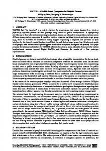
8 INTEGRATION INTO A 3D GIS The CityServer3D1 is a client-server system for the storage, visualisation, and processing of spatial data. Geo information from different sources is integrated into an object-relational database and placed in the web at the disposal of different clients. The CityServer3D is most often used for managing 3D city models in the urban management and planning domain. The CityServer3D AdminTool is a desktop application providing features, such as importing and exporting spatial data into the local workspace or into the CityServer3D database. The tool also offers features for data editing, 3D visualization and quality assurance. The user interface of the AdminTool can be customized with different views, depending on the customer’s requirements. The most used and most important views are the explorer view for an hierarchic overview of the loaded spatial data, the 3D view for visualization and the 2D view for orientation (see figure 5 from left to right). In addition there are pre-built perspectives representing the various views in different alignments. We integrated the graphical editor in the so-called ‘project perspective’ (see figure 6). This perspective allows users to create several projects to integrate data sources and to apply automated, geospatial processes to them.
Fig. 5: The CityServer3D AdminTool consists of a data explorer, a 3D visualization and a 2D map (from left to right).
Fig. 6: The CityServer3D AdminTool’s project perspective 1
http://www.cityserver3d.de
106
REAL CORP 2014: PLAN IT SMART
Michel Krämer, Andreas Stein
The report view (on the bottom of figure 6) is used for feedback while executing a rule. If an object could not be changed or filtered by the rule for any reason, a report will appear in this view with a feedback message and a link to the said object. The project view (on the left of figure 6) offers the possibility to link specific data sources and grant an overview of all created rules. The graphical editor itself is subdivided in three parts (see figure 7). The tool bar on the left side contains all recipes available in the selected cookbook. The brown recipes are conditions. They filter objects by different criteria—e.g. appearance, location, size or metadata. The other recipes are actions and differ by their function. Blue recipes are for editing, green ones are for creating and red ones are for deleting data. The action recipes are placed on the lower right side of the editor.
Fig. 7: The user interface of the graphical rule editor
9 EVALUATION In order to evaluate the usefulness of our implementation a workshop with urban planners from the user community of the urbanAPI project was held. We presented the graphical rule editor and asked participants to design their own workflows with it. We then provided a questionnaire where we asked them to evaluate the rule editor. From a technical perspective, the evaluation shows that our implementation helps users automate processes and that it is relatively easy to use. They understood its functionalities and purpose and were able to use it to design selected workflows. However, at the current state the editor only provides a small set of recipes that are targeted to use cases in urbanAPI specifically. Due to that, the editor is not yet flexible enough to be used in more advanced scenarios. Consequently, one of the next steps will be to implement more recipes that target a wider range of geospatial/urban use cases. Additionally, users pointed out that there has to be some introductory material for the rule editor in order to make it easier for new users to understand its concepts and functionality. In the future we will create tutorials that will guide the user through a simple example in order to make them familiar with the rule editor. Finally, the usability of the individual recipes can be further improved by implementing additional features such as greater/less comparison for metadata, selection of extents out of a 2D map, etc. 10 CONCLUSION In this paper we presented the results of integrating a graphical editor for domain-specific languages into a 3D GIS. We described language elements and how we categorized them into recipes and cookbooks. Recipes are language constructs that can be used in various applications. In order to achieve good usability, we
Proceedings REAL CORP 2014 Tagungsband 21-23 May 2014,Vienna, Austria. http://www.corp.at
ISBN: 978-3-9503110-6-8 (CD-ROM); ISBN: 978-3-9503110-7-5 (Print) Editors: Manfred SCHRENK, Vasily V. POPOVICH, Peter ZEILE, Pietro ELISEI
107
Automated Urban Management Processes: Integrating a Graphical Editor for Modular Domain-Specific Languages into a 3D GIS
grouped these recipes into cookbooks which actually represent the vocabulary tailored to specific application domains or use cases. In order to allow the user to specify complex workflows we used production rules that can be chained. Geospatial processing can be rather complex and time consuming, especially if the same process has to be performed over and over again. We think that production rules can help alleviate this problem. However, typically rule-based systems are quite generic and very flexible. This makes them hard to use for domain experts with no background in computer science. We expect domain-specific languages to help domain experts to express geospatial processes in their own words. This makes specifying workflows easier, especially when the language constructs are grouped into recognizable, reusable elements like the recipes we proposed. In this paper we also presented guidelines for choosing the right granularity while designing new recipes. In our experience, these guidelines lead to recipes that are reusable in a wide range of applications and at the same time very understandable for domain experts. We also described a workflow for domainspecific language design that makes use of storyboards and ontologies to identify the right domain vocabulary. In order to show how our approach works, we presented the implemented user interface and how we applied our approach to a practical scenario. Feedback gained from urbanAPI community was positive and we will continue to develop this approach in the future. 11 ACKNOWLEDGEMENTS Research presented here is partly carried out within the project “urbanAPI” (Interactive Analysis, Simulation and Visualisation Tools for Urban Agile Policy Implementation), funded from the 7th Framework Program of the European Commission, call identifier: FP7-ICT-2011-7, under the grant agreement no: 288577, started in October 2011. 12 REFERENCES CHAFI, H.; DEVITO, Z.; MOORS, A.; ROMPF, T.; SUJEETH, A. K.; HANRAHAN, P.; ODERSKY, M.; OLUKOTUN, K.: Language virtualization for heterogeneous parallel computing. In Proceedings of the ACM international conference on Object oriented programming systems languages and applications - OOPSLA ’10, vol. 45, no. 10, page 835, 2010. FOWLER, Martin: Domain-Specific Languages. Addison-Wesley Longman, Amsterdam, 2010. GAŠEVIĆ, Dragan; DJURIĆ, Dragan; DEVEDŽIĆ, Vladan: Model Driven Architecture and Ontology Development. Springer, Berlin-Heidelberg, 2006. KRÄMER, Michel; LUDLOW, David; KHAN, Zaheer: Domain-Specific Languages For Agile Urban Policy Modelling. In Proceedings of the 27th European Conference On Modelling and Simulation (ECMS), edited by Webjørn Rekdalsbakken, R.T. Bye and H. Zhang, 673-680. Ålesund, Norway, 2013. LEE, H.; BROWN, K.; SUJEETH, A.; CHAFI, H.; ROMPF, T.; ODERSKY, M.; OLUKOTUN, K: Domain-Specific Languages for Heterogeneous Parallel Computing. IEEE Micro, vol. 31, no. 5, pages 42-53, 2011. NICOLA, A. D.; MISSIKOFF, M., NAVIGLI, R: A software engineering approach to ontology building. Information Systems 34, pp. 258–275, 2009.
108
REAL CORP 2014: PLAN IT SMART