Oct 24, 2003 - G. Zhang, T. Yang, S. Gregori, J. Liu, F. Maloberti: "Ultra-low power motion triggered ..... and Zhang, Mao-Zhu, âA foveated silicon retina for.
G. Zhang, T. Yang, S. Gregori, J. Liu, F. Maloberti: "Ultra-low power motion triggered image sensor for distributed wireless sensor network"; Proc. of IEEE Sensors 2003, Toronto, 22-‐24 October 2003, Vol. 2, pp. 1141-‐1146. ©20xx IEEE. Personal use of this material is permitted. However, permission to reprint/republish this material for advertising or promotional purposes or for creating new collective works for resale or redistribution to servers or lists, or to reuse any copyrighted component of this work in other works must be obtained from the IEEE.
ULTRA-LOW POWER MOTION-TRIGGERED IMAGE SENSOR FOR DISTRIBUTED WIRELESS SENSOR NETWORK Guangbin Zhang, Tianhong Yang, Stefano Gregori, Jin Liu, Franco Maloberti Electrical Engineering Department, University of Texas at Dallas, hchardson, Texas, USA gbzhang, thy021000, Stefano, jinliu, franco maloherti @utdallas edu Abstract
This paper describes a motion-triggered CMOS image sensor. It uses low resolution photosensor array with an ultra lowpower data converter in the read out circuit. The analog motion sensor shares the same photosensors using an interleaved structure. The motion sensor triggers the digiial imager and RF data transmission to the base station in case there are objects moving in the scene, otherwise, the system remains standby to save power. This design is specially optimized for veiy low power applications such as distributed wireless sensor network. Keywords
Low power, CMOS imager, motion sensor INTRODUCTION
r 1 -
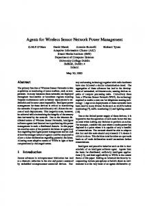
This paper describes the integrated electronic circuits of a generic sensor platform for a distributed wireless sensor network. The device is powered by on-board microbatteries which are remotely rechargeable via microwave from the base station. Since the radiation regulation limits the maximum microwave power, the available power for the remote sensors is extremely low. In this paper, we focus on an ultra-low power motion triggered image sensor. Fig. I presents the sensor module architecture. The power is provided by microwaves from the base station while a RF signal is used to send data to the base station. A DSP will be used to control the functioning of the whole sensor and the communication with the base station. A power management unit manages the power supply of the chips. The module is intended for any possible plug-in sensor. However; optical sensors are the most challenging elements in terms of power consumption and required transmission bandwidth. The total power budget is 1OOpW. By optimizing the pixel and A/D converter design, we obtained a very low power digital 2-D image sensor which dissipates less than 35pW. However, when the imaging acquisition and transmission is on, the DSP and RF part consume much more power, exceeding 1OOpW when certain data rate is required. Fortunately, for a security camera surveillance system, it is not necessary to keep the camera and RF data transmission on all the time, unless there are movements in the scene. So, when the scene is stationary, it is possible we turn off the digital camera system and go to standby mode. When the system is in acquisition mode, it is easy for the base station to send a command to the re0-7803-8133-5/03/$17.00 02003 IEEE
, I
digitalhnapr
I
I
A I
I
I
I
DSP I
I
F3mivu
I
-
-
c -
POWU
Fig. I. Motion triggered image sensor for distributed wireless sensor network
ARCHITECTURE OF MOTION TRIGGERED IMAGE
SENSOR
Fig. 2 shows the interleaved structure for the motion sensing operation. An additional transistor is added into each pixel to set the operation modes. In acquisition mode, we sample each pixel frame by frame using a column/row selection circuit and a single ADC to obtain digitized data. In standby mode, the digital camera is off, and the added transistors are turned on to connect the photo current outputs to the motion sensor cells. We connect every other pixel in the even columns to the x-axis I-D motion sensor array to detect horizontal motion, and connect every other pixel in the even row to the y-axis 1-D motion sensor array to detect vertical motion, respectively. A decision circuit compares the motion sensor output with a threshold to decide whether to turn on the system or not. Since the digital imager and the motion sensor are integrated on a single chip and share the same set of photosensors, only one set of 1141
optical lenses is required to realize compact design. The picture shows only a 6 x 6 array as an example, but the actual demo image sensor contains a digital imager of 64 x 64 photodiodes and two 16 x 1 analog motion sensor array, with layout on a 2mm by 2mm mini-chip in TSMC 0.18pm process.
before, the system measures the change resulting from the integration of the photo current in a storing capacitor C, directly and does not require a charge amplifier. When a given pixel is selected, the charge on the storing capacitor is shared with the capacitors array of the successive approximation network. Since the storing capacitor equals the value of the entire SAR array, the signal is divided by two. In reality, if accounting for the parasitic effects, the final read voltage, Vx, is about half of the original voltage, V, stored in C,. This relationship can be expressed as
v,=v
c,
2c,+c,'
where C, is 0.4pF and C, is the sum of the diode capacitance and 64 transistor diffusion-substrate capacitances. In this case, C, is around 17OfF, and the final read out voltage is 0.4 times of the original voltage stored in C,. To make the ratio close to 0.5, larger C, can be used.
Mollom -lor
b%oh
Fig. 2. Interleaved structure of combined digital imager and analog motion sensor
I I$ ---TI \-
THE LOW POWER DIGITAL.IMAGER Fig. 3 shows typical structure of a passive pixel image sensor. The pixel array shares one charge amplifier which consume the largest portion of power in this architecture. To minimize the power, the proposed schematic is shown in Fig. 4. The entire array shares one single A/D converter and the charge amplifier is eliminated.
1 -.*.
./--
_I
1-
Flg.4. Proposed sensor structure
The layout area of each pixel is 12 x 12 p2. The photodiode are Nwell-Psub, single ring structure. This structure is chosen due to its better responsivity (measured from previously fabricated chip) and good isolation between the pixels [ I]. Since the average photo current is around 0.711.4, the calculated power consumption of photodiodes of 64 x 64 array is 3.44pW.
Low power ADC
vu.ptcw*€=.
IMI
Fig.3. Passive pixel image sensor structure Pixel design and readout circuit
Different !?om conventional solutions, this design uses a successive approximation AiD converter. As mentioned
A significant fraction of the power consumption of image sensor array comes from the analog to digital interface. This chip as already mentioned does not require a charge pre-amplifier, while using a low power comparator in a conventional successive approximation (SA) converter. Fig. 5 shows the SA architecture. The comparator has zero DC current and uses capacitors instead of active loads. A charginddischarging process enables amplifying the input signal. Simulation shows it has 8-bit resolution, averaged
1142
5.7 pW analog and 4.0pW digital power consumption at 200 kHz conversion frequency. Reset:
I?-, : ib >
put every bit cycle. Then, the binary weighted capacitor changed the VA of the comparator.
1
ac' . I
I
,
...
' : - -
i :
... A A D7 D6 D1 DO
I
Fig.7. Structure of SAR
FigS. Low power charge redistribution successive approximation converter
The schematic of comparator used into the ADC is shown in Fig 6. During @ I , the two switches across C1 and C2 discharge the capacitors and bring the ,differential output to Voo. The transistors controlled by @2 keep the input pair off. During @2, the voltage Vb enables M3 and M4 to form cascode configurations with M1 and M2. Capacitors C, and C2 are charged and the output voltages go down. M5 and M6 make a common mode feedback and control the quiescent current across the differential input. At a given point, the current goes to zero and the output voltages reach a steady value. A possible unbalancement of the input voltages leads to an amplified steady output difference. The outputs are then used to drive a latch controlled by the .phase QL, The power consumption of the pre2
amplifier is P, = C,VDDf . In
OUT
Fig. 8 shows some simulated waveforms for the ADC. The difference between input signal and the common voltage (Vdd2 in this architecture) is amplified about ten times by the preamplifier. (a) shows the preamplifier outputs. They dynamically change and they are suitable for controlling a positive feedback latch. (h) shows the latch outputs which are triggered by DL. (c) shows the two inputs signal of the comparator in Fig 5. " 9terminal is kept constant and "A" terminal is changed by SAR according to the comparator output hit. Then the correct output bit is obtained from the S A R through an output buffer.
design CI=Cz=200fF,
Voo=1.5V, f=2MHz. therefore, P,= 0.9pW. The power required by the positive-feedback latch is 1.1pW.
..
-LA
,..
7-
*
_I.>
.
-.. .., L.
I
Fig.& Simulation results for the ADC (a) output signals of preamplifier (b) output signals of latch (c) input signals of
the comparator
*
Fig.6. Low power comparator
*
The control logic 'is generated through successive approximate register (SAR [3]) by registering the comparator out-
Fig. 9 shows the response time of the positive-feedback latch stage. It takes about 4 ns to establish the logic signal with input difference 50mV. However, when the difference of two inputs is lLSB, i.e. 4mV, the time will increase to 5 ns. And the reason that the latch stage in Fig. 6 is chosen is that the outputs of the pre-amplifier are always high in half time and gradually goes low in another half [4][5]. This schematic ensures that there is no static power consumption when the latch works in hold mode. When the latch is triggered, the logic level is achieved in 4ns, so it
1143
only consumes power during the short switching time. An additional SR latch follows the latch shown in Fig. 6. ,I
..
I
.,.
I
IIMI*.C*I..
I
->z-,z,
,,.." I
1
_,.. Fig.9. Response time of the comparator . l l . "
Sampling frequency
2001cHz
Resolution
8hit
Process
0.18pm CMOS
Power supply
1.5V
Power consumption
5.672pW analog 4.007pW
I..
digital FigureofMerit
I
necessarily cause obvious change of luminance for large area. In addition, when the sensor resolution is too low, it cannot distinguish whether a large area light density change is caused by the change of the environment luminance such as adjusting the brightness of a lamp or by motion. To overcome these difficulties while keep the power consumption very low, a new motion detection method is proposed by detecting a moving edge. A static edge in the image is defined sufficient light density contrast between neighboring pixels; the moving of the edge is detected based on the change of the contrast between neighboring pixels. In this approach, the moving edge is detected by directly comparing the outputs of the neighboring pixels without using active delay elements or filter circuits to generate a second version of signal to compare with. As a result, this design largely reduces the power consumption by using simple static logic circuit. Fig. 10 shows the architecture of the I-D motion sensor. The edge detectors use the outputs from neighbor pixels to detect the moving edge. The detected moving edge pulses from different locations are then added up together by a pulse fusing circuit. The output of the fusing circuit drives the decision circuit to count the pulses by charging a capacitor. Then, the voltage on this capacitor is compared with a threshold voltage pre-set by the user. Once it reaches a certain voltage level, it means there are substantial movements in the scene so the motion sensor will output an 'enable' signal to trigger the digital image acquisition to start. A 1 . W power supply is used for all parts of the motion sensor.
0.189pJlconversion
THE LOW POWER ANALOG MOTION SENSOR
CMOS motion sensor chips have been developed during the past 15 years [6][7][8][9][10]. Many visual chips detect motion by tracking the disappearance of an edge and its subsequent reappearing at neighboring pixel, using an edge detector. Typical design of the edge detector compares the concurrent signal with the temporally delayed version, or spatially smoothed version to find out edges. However, these approaches normally lead to active delay elements or filters, which require some of the transistors working in saturation region.. A typical'value of the power consumption per pixel of these motion sensors is about 50pW, thus, the power consumption for a 32x1 motion sensor array is ahout 1600pW. This is acceptable for most applications, but not for the RF powered distributed wireless sensor system which requires extreme low power operation. One solution to reduce the power is to use fewer pixels. However, very low resolution may decrease the spatial sensitivity, since the small area movements may not
...... ......
edge ddostol
piid
1
pii.11
=.I3
Fig. I O . Motion detection and trigger circuit. Motion edge detector
Fig. 11 shows the schematic of the edge detector. The photocurrent is applied to two cascaded diode-mode P-type MOSFETs to obtain log scale current-voltage mapping. Simulation shows it has 6 decades or 12OdB of linear re1144
~
sponse range (from IpA to IPA) with 205mV voltage drop per decade. A Hysteresis comparator is used to.compare the neighboring pixel outputs. The Hysteresis shift voltage is VSh=flOmV.
After the comparator, an NXOR based digital edge detector is used to convert each rising and falling edges of the comparator output to a single narrow pulse. The pulse width is tuned by adjusting the output impedance of the inverter and the load capacitor; in this design, it is 20ns.
Pulse fusion circuit and decision circuit Fig. 12 shows the schematic of the pulse fusion and decision circuit. Most of the time the N-MOSFETs ml mk controlled by the detected edge pulses are tumed off so that the voltage on C3 remains high. When a moving edge occurs, one of the N-MOSFETs ml I& is tumed on to discharge C3. C3 will be recharged to high voltage when all ml to mk are off. Since all the drain nodes of ml to IQ are connected together to C,, the pulses are fused into one pulse. However, since the charging process of C3 is much slower than the discharging process, the pulse width on C3 will he expanded compared with the original pulses. Then, a second digital pulse extractor is used to obtain a fixed width narrow pulse. This pulse extractor is similar to the one used previously, but, a NAND gate is used instead of NXOR gate for extracting the falling edges only. The obtained short pulse is fixed at 1711s pulse width. We use this pulse to control the step-by-step charging process of CI. C1 can also be discharged by ‘Clear’ signal from the DSP to reinitiate the motion detection process. The PMOSFET and NMOSFET connected to CI are in cascode structure in order to reduce the leakage current when both the P-type and N-type MOSFETs are off and the charge on C l will be maintained for some time. The decision whether to wake up the digital imager is based on the comparison of the voltage on C, with a threshold voltage. The threshold voltage, Vth, is adjustable by user extemally. It can he configured to ignore certain level of non-continuous or small scale motion by setting Vth higher than quiescent voltage across CI when no edges occur.
-
-
Fig. 11. Edge detector
If the output of the neighboring pixels as marked as ‘a’ and ‘b’, and the output of the comparator is marked as ‘c’, the motion detection algorithm is shown as Table 2. Table 2. Motion detection algorithm
ah+VSh
c=high
a2b+VB
c=high
No
T
I m,
......
Fig. 12. Pulse fusion and decision circuit
Simulation results
Fig. 13 shows the simulation results. The first two plots of loland Io2 are the light density of neighboring pixels. The time offset of the two inputs indicates movement of objects, which is detected as shown in the third plot of short 1145
~
pulses named as ‘MvEdge’. All the short pulses are added together by,the fusing circuit. The fused pulses are used to charge the capacitor C,, the voltage across’which is shown in the fourth plot, named ‘storage’. It increases step by step. After the ‘storage’ voltage on the capacitor reaches the threshold, Ve, the output ‘En’becomes high and trigger the digital camera, the DSP chip, and the RF driver to begin sampling and transmitting’data. The simulated average power consumption for two 16 x 1 motion sensor arrays is 0.506pW per cell at IOOpA background photo current per pixel. And the pulse fusioddecision circuit cost 2.946pW. Thus, the total power for the two 16x1 sensor is only 19.138pW.
[2] McCreary, J.L. and Gray, P.R., “All-MOS charge redistribution analog-to-digital conversion techniques 1”. Solid-State Circuifs, IEEE Youmal of, Volume, I O Issue 6 , Pages 371-379, Dec 1975 [3] Russell, H., “An improved successive approximation register design for use in AID converters”. Circuits and Systems, IEEE Transactions on, Volume. 25 Issue 7 , Pages 550 -554, Jul 1978 [4] Amaral, P., Goes, J., Paulino, N., and Steiger-Garcao, A., “An improved low-voltage low-power CMOS comparator to be used in high-speed pipeline ADCs” Circuits and Systems, 2002. ISCAS 2002. IEEE Internafional Symposium on , Volume: 5 , 26-29, Pages V-141 - V I 4 4 vo1.5, May 2002 [5] Sumanen, L., Waltari, M., Hakkarainen, V. and Halonen, K., “CMOS Dynamic comparators for pipeline A D converters” Circuits and Systems, 2002. ISCAS 2002. IEEE International Symposium on, Volume. 5 , 26-29, Pages V-157 -V-160 vo1.5, May 2002 [6] Higgins, C.M., Deutschmann, R.A., Koch, C., “Pulsebased 2-D motion sensors”. Circuits and Systems 11 Analog and Digital Signal Processing, IEEE Transactions on, Vol. 46, 1999 pages 677-687
-
*e
..U
2-
.-
..
=
.“
.-.c,
(1
Fig. 13. Simulation results for the motion sensor
[7] Ogmen, H. and Gagne, S., “Neural Network Architectures for Motion Perception and Elementary Motion Detection in the Fly Visual System,” Neural Networks, vol. 3, pp. 487-505, 1990.
[8] Etienne-Cu”ings,R., Van der Spiegel, J., Mueller, P.
and Zhang, Mao-Zhu, “A foveated silicon retina for two-dimensional tracking,” IEEE Transaction on Circuits and Systems 11: Analog and Digital Signal Processing, Vol. 47, Issue 6, pp. 504 -5 17, June 2000.
SUMMARY
This paper has presented a motion triggered ultra-low power CMOS image sensor containing two parts: digital imager and analog motion sensor. They share the same set of photosensors by an interleaved structure. Both the digital imager and the motion sensor are optimized for very low power consumption. The 64x64 pixel digital imager consumes less than 35pW at 200k sampling frequency, including a very low power AD converter which only needs IOpW. The b o 16x1 motion sensor arrays consume less than 20pW totally, which is much less than the typical work in the literature. The motion sensors act as a monitor when the system is standby and bigger the image acquisition and RF transmission when motion is detected.
[9] Li, Z., Aizawa, K. and Hatori, M., “Implementation of a 2 0 motion vector detection on image sensor focal plane,” Proceedings of the 1999 IEEE International Symposium on Circuits and Systems, Vol. 5 , pp. 156 159, 1999 [IO] Moini, A., Bouzerdoum,A., Eshraghian, K., Yakovleff, A., Nguyen, X. T., Blanksby, A., Beare, R., Abbott, D., and Bogner, R. E., “An insect vision-based motion detection chip,” IEEE Journal of Solid-state Circuit , Vol. 32, Issue: 2, pp. 279 -284, February 1997
ACKNOWLEDGEMENT
The work is supported by National Science Foundation project ECS-0225528. REFERENCES
[ l ] Goy, J., Courtois, B., Karam, J.M., ‘‘Design of an APS CMOS image sensor for Low light level applications using standard CMOS technology”, Analog Integrated Circuifs and Signal Processing, Kluwer Academic Publishers, volume, 29 pages 95-104,2001 1146