IEEE TRANSACTIONS ON INSTRUMENTATION AND MEASUREMENT, VOL. 58, NO. 5, MAY 2009
1471
Autonomous Sensor System With Power Harvesting for Telemetric Temperature Measurements of Pipes Simone Dalola, Vittorio Ferrari, Member, IEEE, Michele Guizzetti, Daniele Marioli, Member, IEEE, Emilio Sardini, Member, IEEE, Mauro Serpelloni, and Andrea Taroni, Member, IEEE
Abstract—In this paper, an autonomous sensor system, with low-power electronics for radio-frequency (RF) communication, incorporating a thermoelectric energy-harvesting module for unattended operation is presented. A target application is proposed for temperature measurement of walled-in pipes. When the autonomous sensor is placed on the heat source, a thermoelectric module harvests energy, powering the autonomous sensor. In this condition, no external power source is necessary, the temperature measurement is performed, and the data are saved into a nonvolatile memory. When the external readout unit is active, the electromagnetic field is used to power the autonomous sensor system and to communicate the data. An experimental setup has been arranged and characterized by measuring the temperature along the pipe, the voltage that can be generated by thermoelectric generators, and the influence of different materials on RF communication. The temperature data of the heat source, which are collected by the autonomous sensor, are compared with that of a reference thermistor. The measurement results show good agreement between the two measured temperature data sets. The experimental data demonstrate that the autonomous system works correctly for a temperature gradient that is higher than 9 ◦ C, within a readout distance of a few centimeters. The presented autonomous sensor system can be effectively used for measurements into a close environment in which a temperature difference is present. Index Terms—Autonomous sensor, energy scavenging, power harvesting, telemetric system, temperature measurements, walled-in pipes.
I. I NTRODUCTION
A
UTONOMOUS sensors, which can be interrogated contactless and exploit the locally available energy for powering themselves, are attractive for operation in applications that do not allow the use of cabled solutions, e.g., in-package [1]–[3] or in-body measurements [4], where traditional solutions present wiring problems, and the use of batteries need appropriate maintenance and disposal. In many applications reported in the literature [1]–[5], the autonomous sensing system uses the electromagnetic field as power supply. The transmitted electromagnetic signal of the
Manuscript received July 1, 2008; revised December 2, 2008. First published February 10, 2009; current version published April 7, 2009. The Associate Editor coordinating the review process for this paper was Dr. Salvatore Baglio. S. Dalola, V. Ferrari, M. Guizzetti, D. Marioli, E. Sardini, and M. Serpelloni are with the Department of Electronics for Automation, Faculty of Engineering, University of Brescia, 25123 Brescia, Italy (e-mail: mauro.
[email protected]). A. Taroni is with the Università “Carlo Cattaneo” (LIUC), 21053 Castellanza, Italy. Digital Object Identifier 10.1109/TIM.2009.2012946
external readout unit is used to both power the passive system and communicate the data. This way, however, the sensor works only at the time when the system is interrogated by the readout unit. To allow the possibility of performing the measurement when needed, independently from the presence of the readout unit, power harvesting can be used to power the batteryless system. An autonomous sensor system, with low-power electronics for radio-frequency (RF) communication and with an energy-harvesting module, could be a useful instrument for the measurement of temperature along sections of a domestic or industrial plant for efficiency evaluation. Temperature values along the section of a heating or cooling plant are important indicators to control hot combustion gases [6] and its efficiency [7]. Some examples reported in [8] and [9] suggest new techniques in the control of building heating plant. Thermal energy harvesting can be a solution for the retrieval of freely available ambient energy, allowing the development of energyautonomous sensing nodes [10]–[12]. Thermal gradients can be exploited by thermoelectric converters used as powerharvesting devices. In [13], a large thermoelectric converter is described for the generation of electricity from hot exhausts on vehicles. BiTe-alloy-based commercial thermoelectric generators (TEGs) have typical power density with values of 0.4 ÷ 4 μW/mm2 for a temperature difference of 5 ◦ C [14]. At a smaller scale [12], for a temperature difference of 5 ◦ C, microfabricated devices show power densities of 0.14 μW/mm2 for 700 mm2 , 0.37 μW/mm2 for 68 mm2 , and 0.60 μW/mm2 for 1.12 mm2 . Temperature differences are available in various applications, with values ranging from few degrees, e.g., in wearable-device applications, to tens of degrees, for building environments [12]. When exposed to constant-temperature gradients, thermopiles generate dc output voltages. The voltage values are usually too low and unregulated for directly powering electronic circuits, although the available current has values up to 100 mA [14], [15]. In order to power autonomous systems, the converted energy must be properly handled, and in particular, the thermopile output voltage must be increased and regulated. In this paper, an autonomous sensor system with low-power electronic RF communication capability, which is equipped with a thermal energy-harvesting module, is presented. The autonomous sensor system performs temperature measurements, exploiting environmental thermal gradients for its power supply. An external unit reads the data that were previously acquired by the autonomous sensor. The temperature measurement of walled-in pipes is proposed as a target application.
0018-9456/$25.00 © 2009 IEEE
Authorized licensed use limited to: Emilio Sardini. Downloaded on November 9, 2009 at 05:04 from IEEE Xplore. Restrictions apply.
1472
IEEE TRANSACTIONS ON INSTRUMENTATION AND MEASUREMENT, VOL. 58, NO. 5, MAY 2009
Fig. 1. Block diagram of autonomous sensor system and readout unit.
II. D ESCRIPTION OF A UTONOMOUS S ENSOR S YSTEM The proposed system consists of an autonomous sensor and an external readout unit. The autonomous sensor system performs temperature measurements, exploiting environmental thermal gradients for its power supply. It includes a TEG with the related electronics for the management and conversion of power, so it does not require any external electric power source. The system incorporates a Radio-Frequency IDentification (RFID) module providing signal transmission via electromagnetic coupling at 125 kHz for the communication with an external readout unit. The advantage of transmitting an electromagnetic field at such a comparatively low frequency is the possibility to more effectively transfer data and power through different interposed materials without a cabled link. The system implements strategies to reduce the power consumption. The sensor module is designed to be triggered to transmission only when required, thereby consuming less power because unnecessary transmissions are avoided. A block diagram of the proposed autonomous sensor system and readout unit is shown in Fig. 1. It consists of different modules: a low-power temperature sensor, which measures the temperature of a heat source; a low-power microcontroller for the analog-to-digital conversion of the data, the storage into a flash memory, and the telemetric operation; an RFID telemetric transponder, which transfers the data collected to the readout unit; and a voltage dc–dc converter to boost the output voltage of the thermoelectric module. The low-power temperature sensor LM94022 is a precision analog output CMOS integrated-circuit temperature sensor that operates at a supply voltage as low as 1.5 V with an accuracy of about 1.5 ◦ C. The adjustable gain is set to obtain a good tradeoff between sensitivity and power consumption so that the specified sensitivity was set to −8.2 mV/◦ C.
To transmit data, the 125-kHz RFID transponder U3280M modulates the magnetic field using a damping stage; in particular, the on–off keying (OOK) modulation and the Manchester code are chosen. The clock extractor pin is used to provide a field clock for the synchronization of data transfer. The transponder interface can also receive data. The readout unit modulates the data with short gaps in the field, and a gapdetection circuit reveals these gaps and decodes the signal. Moreover, the device is able to generate a power supply, which is handled via electromagnetic field and the coil antenna of the transponder interface. The low-power microcontroller chosen is the Freescale 9S08QE128, which includes a 12-bit ADC, a 128-kB flash memory to save the data, and a timer unit that permits the synchronization of the data transmission. To maintain low power consumption, the bus frequency is fixed to 460 kHz, the ADC and the flash programming unit have a low-power configuration, and all the unused peripherals are switched off. The power-harvesting stage consists of a TEG and a dc–dc converter. The used TEG is the module TGM-254-1.0-1.3 by Kryotherm with dimensions of 40 × 40 × 3.6 mm3 , which is composed of 254 thermocouples connected electrically in series and thermally in parallel. When a temperature difference ΔT is applied between the TEG faces, an open-circuit output voltage VG is generated according to the following: VG = N αΔT
(1)
where α is the Seebeck coefficient of the TEG materials (368 μV/◦ C), N is the number of thermocouples (254), and ΔT is the temperature difference applied. The output power PL delivered by the TEG to the load RL is given by the following relationship: PL = N 2 α2 ΔT 2
RL (RL + Rin )2
(2)
where Rin is the internal electrical resistance of the TEG. The power density of the adopted TEG module is 4 μW/mm2 for a temperature difference ΔT of 5 ◦ C in matched-load conditions. The dc–dc converter TPS61200 is the used voltage boost (step-up) converter that switches on when the input voltage goes beyond 0.5 V, providing a regulated output voltage that is set to 2.1 V. The external readout unit consists of a read/write base station U2270B, which is able to supply power to the transponder driving the coil antenna and to demodulate the digital signal. The readout unit is supplied by a 5 V voltage supply. The operating voltage of the microcontroller is 5 V, and the bus frequency is 7.38 MHz. A timer unit is used to decode the demodulated signal, and the data collected are transferred to a personal computer using a serial communication interface. III. C HARACTERIZATION OF A UTONOMOUS S ENSOR S YSTEM The output voltage generated by the TEG as a function of the temperature difference applied was measured. The TEG
Authorized licensed use limited to: Emilio Sardini. Downloaded on November 9, 2009 at 05:04 from IEEE Xplore. Restrictions apply.
DALOLA et al.: SENSOR SYSTEM WITH POWER HARVESTING FOR TEMPERATURE MEASUREMENTS OF PIPES
1473
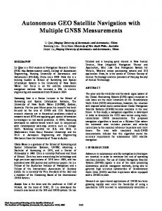
Fig. 2. Power generated by the TEG versus the load resistance for some applied temperature difference.
Fig. 4. Wake-up signals with the power-harvesting module.
Fig. 3. Measured output voltage of TEG. VG —Open-circuit output voltage. VL —Output voltage in loaded condition.
characterization was performed by heating one side of the module by means of a heater, which was externally powered, while a heat sink was applied on the other side to maintain it at a lower temperature by using the setup described in [14]. The temperature difference ΔT between the two faces of the TEG was measured using two NTC thermistors, which were attached with thermoconductive grease. The output power generated by the TEG, which was measured under different load conditions and various applied temperature gradients, is shown in Fig. 2. As expected from (2), the output power has a maximum when RL matches Rin , which, in our case, is about 8 Ω. The output voltage of the TEG was then measured versus the applied temperature difference ΔT in the range from 0 ◦ C to 13 ◦ C in both open-circuit and loaded conditions, which was reported as VG and VL , respectively. In the loaded condition, the dc–dc converter, temperature sensor, and microcontroller are powered by the TEG. The obtained experimental results are shown in Fig. 3, which reports both VG and VL as a function of the temperature difference ΔT . As expected from (1), the open-circuit output voltage VG and the temperature difference ΔT are directly proportional. When the temperature difference is lower than about 3 ◦ C, the TEG voltage is less than 0.3 V, and the dc–dc converter is off. In this case, there is no loading effect on the TEG, and the curves of VG and VL overlap. When ΔT goes beyond 4 ◦ C (“Intermediate phase”), the dc–dc converter attempts to switch on, sinking a comparatively high current that decreases the
voltage VL . In this condition, the output voltage VCC of the dc–dc converter is lower than the set value of 2.1 V. When ΔT reaches a value of about 8.5 ◦ C and above, the dc–dc converter switches on completely, and its output voltage steadily goes to 2.1 V. The autonomous sensor has two different operational modes: measurement and data-saving mode, which is powered by the TEG module, and RF communication mode, which is powered by the magnetic field generated by the external readout unit. In Fig. 4, the main signals, which are the output voltage of the TEG module (VL ), the output voltage of the dc–dc converter (VCC ), and the microcontroller clock, are shown during the system wake-up due to the increase of the power-harvesting supply. In the initial time interval (“Start-up boost converter”), when VL exceeds 300 mV, the dc–dc converter begins to start up, and when VL exceeds 0.5 V, the dc–dc converter is completely on, generating a stable output voltage of 2.1 V. From this moment, the sensor and the microcontroller are powered, and the system works continuously as long as the temperature gradient is maintained. During the “Start-up μC” time interval, when the dc–dc converter output voltage VCC reaches 1.8 V, the microcontroller begins to switch on. In the performed tests, the autonomous sensor system, when powered by the TEG, can save the measurement data into a nonvolatile memory every 2 s. In this situation, the microcontroller and the temperature sensor require a power supply of about 0.9 mW, with a current consumption of about 0.4 mA and a voltage level of about 2.1 V. The measured data can then be collected at subsequent times using the external readout unit by RF communication. In the reading operation, the presence of a heat source is not strictly necessary, since the power supply is provided via electromagnetic field through the coil antenna of the transponder interface. The wake-up signals when the RF field supplies the sensor are shown in Fig. 5. The signals are the differential voltage of the reader antenna, the voltage of the transponder antenna, the supply voltage of the microcontroller, and the microcontroller clock. In the time interval labeled as “Start-up transponder,” the reader is turned on, and the electromagnetic field begins to power the transponder. In the second time interval labeled
Authorized licensed use limited to: Emilio Sardini. Downloaded on November 9, 2009 at 05:04 from IEEE Xplore. Restrictions apply.
1474
IEEE TRANSACTIONS ON INSTRUMENTATION AND MEASUREMENT, VOL. 58, NO. 5, MAY 2009
TABLE I MEASURED POWER OF THE TWO OPERATIONAL STATES OF THE AUTONOMOUS SENSOR
TABLE II TYPICAL CURRENT CONSUMPTION
Fig. 5. Wake-up signals with the RF power supply provided by the external readout unit. TABLE III ANTENNA CHARACTERISTICS
Fig. 6. Wireless transmission of the recorded temperature data.
as “Start-up μC,” the transponder is turned on, while the microcontroller begins to be powered. The total wake-up time is about 100 ms. The data communication starts after 20 ms from microcontroller clock wake-up, as shown from the transponder antenna signal. A transmission of the measured temperature data that were previously stored in the flash memory between the autonomous sensor and the readout unit is shown in Fig. 6. The lowpower microcontroller sends the digital signal to the transponder (“Digital signal transponder”) for the transmission. In the lower graph of the figure, the sensor antenna signal is reported, and the OOK modulation of the digital signal is visible. The base station receives the back-reflected signal (“Output Signal Base Station”) and extracts the Manchesterencoded information (“Digital Signal Base Station”). In this experimental configuration, by turning off the unnecessary modules of the microcontroller and keeping a distance between the autonomous sensor and the readout unit of about 15 mm, the current consumption during RF communication is about 190 μA at 2.58 V, corresponding to a power level of 0.5 mW. The power required by the autonomous system in the two operational states are reported in Table I, while Table II shows
Fig. 7. Transponder voltage supply for different distances and in an axial configuration for different antennas reported in Table I.
the values of the current for each device of the autonomous sensor in the two operational states. The measurements are obtained using two multimeters (Fluke 8840A). Different tests to evaluate the maximum operating distance between the autonomous sensor and the readout unit were performed, also varying the dimensions of the sensor antenna. Three antennas, whose characteristics are reported in Table III, have been tested. The inductances have been measured with an impedance analyzer (HP4194A). The transponder voltage supply has been measured with a multimeter (Fluke 8840A) when the autonomous sensor system is transferring data, and the results are shown in Fig. 7. The distance z between the antenna of the readout unit and the autonomous sensor is changed from 50 to 100 mm using a micrometer screw. The correct working operation is achieved
Authorized licensed use limited to: Emilio Sardini. Downloaded on November 9, 2009 at 05:04 from IEEE Xplore. Restrictions apply.
DALOLA et al.: SENSOR SYSTEM WITH POWER HARVESTING FOR TEMPERATURE MEASUREMENTS OF PIPES
Fig. 8.
1475
Scheme of the experimental setup.
for a supply voltage that is higher than 1.8 V. The antenna A1 presents the best readout distance, and it has the largest diameter.
Fig. 9. Scheme of temperature sensor positioning.
IV. E XPERIMENTAL S YSTEM An experimental setup has been arranged to evaluate the capability of the autonomous sensor system to measure the temperature along a walled-in pipe of a heating plant. The experimental system is shown in Fig. 8. It consists of a pipe, throughout which hot air is fluxed, two autonomous sensors, and an external readout unit separated by a dummy wall. The heater system represents a simplified model of a generic building heating plant. A round burner with a diameter of 65 mm has been used as heater, which, when supplied with GPL gas, is able to produce a heating power of about 1 kW. When the gas burner is turned on, it heats the air above it, which generates a hot air flux along the pipe from bottom to top. The hot air is conveyed into a metallic pipe, heating its surfaces. The pipe is made of enameled iron and has a thickness of 1 mm, a square cross section with sides of 100 mm, and a length of 1 m. The external temperature distribution along the pipe was measured using five NTC thermistors placed every 20 cm from the lower end of the pipe, while for the internal hot air temperature, a thermocouple was positioned inside at the center of the pipe, as shown in Fig. 9. The NTC sensors were fixed with thermoconductive grease and sealed with silicon glue. The burner gas flame was set at three different intensity levels. Typical steady-state values of temperatures are shown in Fig. 10, which were measured about 500 s after burner ignition. Two autonomous sensors were placed on the external side of the pipe at 20 and 60 cm from the lower end of the pipe, near NTC 2 and NTC 4, respectively. One side (“hot side”) of the TEG of the autonomous sensor was placed on the external side of the pipe, while on the other (“cold side”), a heat sink was mounted to permit heat exchange with the environment. This allows us to maintain the cold side temperature as low as possible and, as a consequence, a temperature gradient across
Fig. 10. Measured steady-state temperature distribution along the pipe for different gas flame conditions.
Fig. 11. Measured temperature trends along the pipe and output voltage generated by boost converter at medium gas flame condition.
the TEGs as high as possible. The temperature sensor LM94022 was placed near the reference NTC thermistor. Thermoconductive grease was used to improve thermal contact between the pipe wall, TEG, heat sink, and sensor. The output voltages of the dc–dc converters placed near NTC2 and NTC4, which are labeled Vcc1 and Vcc2, respectively, and the time trend of temperatures were measured with the burner gas flame set on medium level, and the obtained data are shown in Fig. 11. It can be observed that the voltages
Authorized licensed use limited to: Emilio Sardini. Downloaded on November 9, 2009 at 05:04 from IEEE Xplore. Restrictions apply.
1476
IEEE TRANSACTIONS ON INSTRUMENTATION AND MEASUREMENT, VOL. 58, NO. 5, MAY 2009
Fig. 12. Autonomous-sensor-measured temperature and reference-NTCmeasured temperature.
generated by the TEGs are high enough to switch on the step-up dc–dc converters with the sensor and microcontroller connected. Fig. 12 shows the temperature of the external pipe side corresponding to the data measured by the two autonomous systems, which were stored in the microcontroller nonvolatile memory and transferred by the external readout unit, and the temperature measured by reference NTC thermistors. The maximum deviations of the temperature values measured by the autonomous sensor from the reference one are about 3.4 ◦ C and 2.8 ◦ C for the autonomous sensors a.s. 1 and a.s. 2, respectively. Moreover, an estimate of the mean-squared deviation of 1.4 ◦ C between the measured data from the reference temperatures was calculated. The autonomous sensor can be placed into an enclosed environment, such as, for the specific testing application, into a wall. In this case, a reduction of the operating distance during the RF communication mode, due to the presence of materials interposed between the sensor and the readout unit, is expected. Different material layers have been used to evaluate the obtainable operating distance. The layers have been positioned between the autonomous sensor and the readout unit antenna to create a dummy wall. The typology of the materials has been chosen to model a real system. The tested materials are as follows: polystyrene (thickness of 6 cm), polyurethane (6 cm), wood (4 cm), glass wool (4 cm), red brick (5 cm), and tiles (4 cm). Metallic layers have been tested as well, but as expected, they produce a shielding action on the communication. The transponder voltage supply was measured with a multimeter when the autonomous sensor system was transferring data and with different materials interposed, as shown in Fig. 13. The antenna “A1” was used. A supply voltage that is higher than 1.8 V guarantees the correct data communication. As expected, the air curve presents the highest readout distance, while the other curves present a readout distance of few millimeters less.
Fig. 13. Transponder voltage supply for different distances and in a nonaxial configuration.
consists of a TEG, a dc–dc converter, a low-power analog temperature sensor, an RFID transceiver, and a low-power microcontroller equipped with an analog-to-digital converter and flash memory. During measuring and data-saving operations, the autonomous sensor system harvests power from the heat source by a thermoelectric module. This is connected to a voltage dc–dc converter to boost the voltage generated by the TEG. During the RF communication, the autonomous sensor is powered by the magnetic field generated by the external readout unit. The proposed sensor has been tested to measure the temperature of walled-in pipes. A simplified apparatus of a generic building heater plant consisting of a gas fire burner and a pipe has been arranged and characterized. Temperature distribution along the pipe and open-circuit output voltage generated by the TEGs positioned at different points have been measured. Two autonomous sensor systems have been applied on the pipe to measure surface temperatures and save data using only the power harvested from the environment. Stored data have then been downloaded by means of the readout unit. The allowable operating distance during the RF communication mode between the autonomous sensor and the readout unit has been evaluated using antennas with different geometric characteristics and different types of interposed material. A maximum readout distance of 8 cm has been obtained when the coils are coaxial. The developed system demonstrates the possibility of powering a sensor, the conditioning and computing electronics, and the communication device by a power-harvesting system, such as a commercial TEG, also in the presence of a lowtemperature difference (less than 10 ◦ C). Transferring the architecture into a purposely designed integrated electronic circuit, like an application-specific integrated circuit system, can contribute to the optimization of the autonomous system representing a solution to further reduce the power consumption and the temperature difference required for operation.
V. C ONCLUSION In this paper, an autonomous sensor with RFID communication and thermoelectric power harvester is described and tested. The device measures the temperature, saves the measured data into a nonvolatile memory, and transfers the memorized data to an external unit by an RF link. The autonomous sensor
R EFERENCES [1] E. L. Tan, W. N. Ng, R. Shao, B. D. Pereles, and K. G. Ong, “A wireless, passive sensor for quantifying packaged food quality,” Sensors, vol. 7, no. 9, pp. 1747–1756, 2007. [2] A. Vergara, E. Llobet, J. L. Ramírez, P. Ivanova, L. Fonseca, S. Zampolli, A. Scorzoni, T. Becker, S. Marco, and J. Wollenstein, “An RFID reader
Authorized licensed use limited to: Emilio Sardini. Downloaded on November 9, 2009 at 05:04 from IEEE Xplore. Restrictions apply.
DALOLA et al.: SENSOR SYSTEM WITH POWER HARVESTING FOR TEMPERATURE MEASUREMENTS OF PIPES
[3]
[4] [5] [6] [7] [8] [9] [10] [11]
[12] [13]
[14]
[15]
with onboard sensing capability for monitoring fruit quality,” Sens. Actuators B, Chem., vol. 127, no. 1, pp. 143–149, Oct. 2007. E. Abada, S. Zampolli, S. Marco, A. Scorzoni, B. Mazzolai, A. Juarros, D. Gomeza, I. Elmi, G. C. Cardinali, J. M. Gomez, F. Palacio, M. Cicioni, A. Mondini, T. Becker, and I. Sayhan, “Flexible tag microlab development: Gas sensors integration in RFID flexible tags for food logistic,” Sens. Actuators B, Chem., vol. 127, no. 1, pp. 2–7, Oct. 2007. A. M. Sodagar, G. E. Perlin, Y. Yao, K. D. Wise, and K. Najafi, “An implantable microsystem for wireless multi-channel cortical recording,” in Proc. Transducers, Lyon, France, 2007, pp. 69–72. S. Yeh, K. Chang, C. Wu, H. Chu, and J. Y. Hsu, “GETA sandals: A footstep location tracking system,” Pers. Ubiquitous Comput., vol. 11, no. 6, pp. 451–463, Aug. 2007. C. Cortes and A. Campo, “Rapid computation of the exit temperature of hot combustion gases flowing inside chimneys,” Appl. Therm. Eng., vol. 19, no. 9, pp. 969–990, 1999. L. E. Juanicó and A. D. González, “Thermal efficiency of natural gas balanced-flue space heaters: Measurements for commercial devices,” Energy Build., vol. 40, no. 6, pp. 1067–1073, 2008. J. Smeds and M. Wall, “Enhanced energy conservation in houses through high performance design,” Energy Build., vol. 39, no. 3, pp. 273–278, Mar. 2007. X. Q. Zhai, R. Z. Wang, Y. J. Dai, J. Y. Wu, Y. X. Xu, and Q. Ma, “Solar integrated energy system for a green building,” Energy Build., vol. 39, no. 8, pp. 985–993, Aug. 2007. R. Y. Nuwayhid, D. M. Rowe, and G. Min, “Low cost stove-top thermoelectric generator for regions with unreliable electricity supply,” Renew. Energy, vol. 28, no. 2, pp. 205–222, 2003. M. A. Sanz-Bobi and R. Palacios, “Potential use of small waste heat sources based on thermoelectricity: Application to an overhead projector and a battery charger,” in Proc. 5th ETS, Pardubice, Czech Republic, 1999, pp. 58–65. C. O. Mathuna, T. O’Donnel, R. V. Martinez-Catala, J. Rohan, and B. O’Flynn, “Energy scavenging for long-term deployable wireless sensor network,” Talanta, vol. 75, no. 3, pp. 613–623, May 2008. M. A. Karri, E. F. Thacher, B. T. Helenbrook, M. S. Compeau, A. Kushch, N. Elsner, M. Bhatti, J. O’Brian, and F. Stabler, “Thermoelectrical energy recovery from the exhaust of a light truck,” in Proc. Diesel Engine Emissions Reduction Conf., Newport, RI, Aug. 24–28, 2003. S. Dalola, M. Ferrari, V. Ferrari, M. Guizzetti, D. Marioli, and A. Taroni, “Characterization of thermoelectric modules for powering autonomous sensors,” IEEE Trans. Instrum. Meas., vol. 58, no. 1, pp. 99–107, Jan. 2009. M. Strasser, R. Aigner, C. Lauterbach, T. F. Sturm, M. Franosch, and G. Wachutka, “Micromachined CMOS thermoelectric generators as on-chip power supply,” Sens. Actuators A, Phys., vol. 114, no. 2/3, pp. 362–370, Sep. 2004.
Simone Dalola was born in Iseo, Italy, in 1982. He received the Laurea degree in electronic engineering from the University of Brescia, Brescia, Italy, in 2007, where he has been working toward the Ph.D. degree in electronic instrumentation with the Department of Electronics for Automation, Faculty of Engineering, since November 2007. He was the holder of a research grant that was funded by the European Social Fund for a research project about autonomous sensors powered by environmental energy. His main research activity deals with the development of autonomous sensors that extract, from the surrounding environment, the energy that is needed for their operation.
1477
Vittorio Ferrari (A’04–M’04) was born in Milan, Italy, in 1962. He received the Laurea degree in physics (cum laude) from the University of Milan in 1988 and the Research Doctorate degree in electronic instrumentation from the University of Brescia, Brescia, Italy, in 1993. From 2001 to 2006, he was an Assistant Professor and an Associate Professor, respectively, with the Department of Electronics for Automation, Faculty of Engineering, University of Brescia, where he has been a Full Professor of electronics since 2006. His research activity is in the field of sensors and related signal-conditioning electronics. His particular topics of interest include acoustic-wave piezoelectric sensors, microresonant sensors and microelectromechanical systems, autonomous sensors and power scavenging, oscillators for resonant sensors, and frequencyoutput interface circuits. He is involved in national and international research programs and projects in cooperation with industry.
Michele Guizzetti was born in Brescia, Italy, in 1981. He received the Laurea degree in electronics engineering from the University of Brescia, in 2006, where he is currently working toward the Ph.D. degree in electronic instrumentation with the Department of Electronics for Automation. His research activity deals with power harvesting and autonomous systems. In particular, he is involved in piezoelectric and thermoelectric energy conversion.
Daniele Marioli (M’04) was born in Brescia, Italy, on January 21, 1946. He received the Laurea degree in electrical engineering from the University of Pavia, Pavia, Italy, in 1969. Since his graduation, he has been involved in research and educational activities with the Politecnico di Milano, Milan, Italy, and the University of Brescia, where he has been a Full Professor of electronics since 1990. He is the chief of the Automation Electronics Department, Faculty of Engineering, University of Brescia. His research interests include the design, realization, and test of sensors, electronic instrumentation, and signal processing electronic circuits. The activities in these fields are related to the realization of innovative sensors in thick-film technology, based on piezoelectric, pyroelectric, and piezoresistive behaviors of screen-printable pastes, and in microelectromechanical systems technology, for the detection of physical quantities (acceleration, force, pressure, mass, etc.); the realization of high-resolution electronic instrumentation for capacitive measurements; the design and realization of integrated electronic circuits as the front end of piezoresistive-based sensors; the development of new linearization techniques based on neural networks; and the development of web sensors and wireless sensors. He is the author or coauthor of more than 200 scientific papers published in international and national journals and conference proceedings and is the holder of four patents.
Emilio Sardini (M’04) was born in Commessaggio, Mantova, Italy, in 1958. He received the M.Sc. degree in electronic engineering from the Politecnico di Milano, Milan, Italy, in 1983. In 1984, he was with the Department of Electronics for Automation, Faculty of Engineering, University of Brescia, Brescia, Italy, where he was an Assistant Professor from 1986 to 1998 and an Associate Professor of electrical and electronics measurements in 1998 and is currently a Full Professor. He teaches courses in electronics instrumentation. His research activity has been on sensors and electronic instrumentation, particularly the conditioning electronics of capacitive and inductive sensors, microprocessor-based instrumentation, the development of thick-film sensors, and instrumentation for noise, as well as for low-frequency acceleration measurements.
Authorized licensed use limited to: Emilio Sardini. Downloaded on November 9, 2009 at 05:04 from IEEE Xplore. Restrictions apply.
1478
IEEE TRANSACTIONS ON INSTRUMENTATION AND MEASUREMENT, VOL. 58, NO. 5, MAY 2009
Mauro Serpelloni was born in Brescia, Italy, in 1979. He received the Laurea degree (summa cum laude) in industrial management engineering and the Research Doctorate degree in electronic instrumentation from the University of Brescia in 2003 and 2007, respectively. He is currently a Research Assistant of electrical and electronic measurements with the Department of Electronics for Automation, Faculty of Engineering, University of Brescia. He has worked on several projects relating to the design, modeling, and fabrication of measurement systems for industrial applications. His research interests include contactless transmissions between sensors and electronics, contactless activation for resonant sensors, and signal processing for microelectromechanical systems.
Andrea Taroni (M’04) was born in 1942. He received the Laurea degree in physical science from the University of Bologna, Bologna, Italy, in 1966. From 1971 to 1986, he was an Associate Professor with the University of Modena, Modena, Italy. From 1986 to 2007, he was a Full Professor of electrical measurements with the University of Brescia, Brescia, Italy. Since 2007, he has been the Rector of the Università Carlo Cattaneo (LIUC), Castellanza, Italy. He has done extensive research in the field of sensors for physical quantities and electronic instrumentation, developing both original devices and practical applications. He has authored more than 100 scientific papers.
Authorized licensed use limited to: Emilio Sardini. Downloaded on November 9, 2009 at 05:04 from IEEE Xplore. Restrictions apply.