can be dramatically modified by this method. Although our results were achieved using a broadband Bragg grating with a flat reflectance spectrum, further tailoring of the spectrum can be achieved using a combination of Bragg gratings with specially tailored reflectance profiles. The key advantage of this design is its flexibility; the spectrum can be tailored to meet the needs of many applications simply by choosing the appropriate Bragg gratings. 27 Novtzmber I997 Electronics Letters Online No: 19980748 S.D. Dyer and K.B. Rochford (National Institute of Standards and Technology, Optoelectronics Division, 325 Broadway, Boulder, CO 80303, USA) E-mail:
[email protected]
References 1
DIGONNET, M.J.F., KIM, B.Y, and SHAW, H.J.: ‘Characteristics of erbium-doped superfluorescent fiber sources for interferometric sensor applications’, J. Lightwave Technol., 1994, 12, ( 3 ) , pp. 550-567 2 HUBER, D.R.: ‘Narrow band incoherent optical carrier generator’. US Patent No. 5,191,586, March 1993 3 TACHIBANA, M., LAMING, R.I., MORKEL, P.R., and PAYNE, D.N.: ‘Erbium-doped fiber amplifier with flattened gain spectrum’, IEEE Photonics Technol. Lett., 1991, 3, (2), pp. 118-120 4 GOODMAN, J.w.: ‘Statistical optics’ (John Wiley & Sons, Inc., 1985) WYSOCKI, P.F.,
Ultrasonic field and temperature sensor based on short in-fibre Bragg gratings N.E. Fisher, D.J. Webb, C.N. Pannell, D.A. J,ackson, L.R. Gavrilov, J.W. H a n d , L. Zhang and I. Bennion The authors demonstrate that in-fibre Bragg gratings may be successfully used to measure megahertz acoustic fields if the grating length is sufficiently short and the optical fibre is appropriately desensitised. A noise-limited pressure resolution of 4.5 x 1e3atm/dHz was found. The capability to simultaneously act as a temperature sensor is also demonstrated. Introduction: There is a need for assessment of the sakty of ultra-
sound for medical applications due to the trend towards increasing output powers from diagnostic ultrasound equipment and the widening use of high intensity ultrasonic fields in a range of therapeutic applications (e.g. [11). Conventional probes use the piezoelectric effect, but such devices suffer from a susceptibility to electromagnetic interference, signal distortion and lack of multiplexing capability. To overcome these ‘electrical’ problems, several approaches utilising optical fibres based on interferometric and polarimetric techniques have been described (e.g. [2, 31). In this Letter, we demonstrate that short in-fibre Bragg gratings (FBG) may also be used to detect high frequency (megahertz) ultrasonic fields. These devices offer distinct advanta.ges such as small diameter, ease of multiplexing, simultaneous measurement of temperature, and potentially low cost.
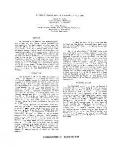
Experiment: The arrangement used to interrogate the grating is
shown in Fig. 1. Light from a 1mW pig-tailed superluminescent diode centred at 824nm with a bandwidth of = 42nm was launched into an unbalanced Mach-Zehnder interferometer (MZI). Incorporated in one arm of the MZI was a phase modulator to frequency shift the light and thus allow the use of pseudoheterodyne signal processing [4]. Provided that the optical path difference between the MZI’s arms is longer than the source coherence length and shorter than the effective coherence length of the back-reflected light from the grating, an interference signal is observed which is in the form of (in the absence of grating strain) a carrier produced by the phase modulator. Strain-induced changes in the Bragg wavelength then induce a corresponding phase modulation of the carrier which we measured by determining the amplitudes of the resulting upper and lower side-band frequency components observed on a radio frequency R F spectrum analyser. The grating had a nominal Bragg wavelength of 820nm, a bandwidth of 0.2nm, a reflectivity of 80?40,and a length of 5“. The transducer was driven continuously in water at its resonant frequency of 1.911MHz, and generated a maximum acoustic pressure of = 2atm (measured using a calibrated PVDF hydrophone) in an acoustical focal spot of radius = 1 2”. ~
Results f o r Smm grating: We observed two anomalies in the
response of the grating to the ultrasonic field: (i) an asymmetry in the magnitudes of the side-band components and (ii) a large homodyne signal at 1.911MHz. We repeated these experiments using sound waves ranging from lOOHz (FBG in air) up to 76kHz (FBG in water). In these cases, we observed the expected system response; hence the anomalies stem from the use of high frequency ultrasound. Now consider Fig. 2 (top), which shows a typical sideband response (normalised to its carrier) with displacement, following a scan of the focal spot along the FBGifibre. Note that the system response extends over a distance that is much greater than the grating length and is periodic. Hence, as we reported in [5], we conclude that compressional standing waves (which can extend many centimetres) are set up by the ultrasound in the fibre (although they are attenuated by the acrylic jackets which are on either side of the grating). Since these waves must only partially modulate the FBG, as their length (3.1” in the case of 1.911MHz) is less than the grating length, this means that the grating is subject to a nonuniJbrm strain which leads to regions of the grating acting as spectral filters for the back-reflected light from other regions of the grating. Our conjecture is that this gives rise to the amplitude modulation (the homodyne signal) which modifies the interferometric signals leading to the asymmetric sidebands.
3
transducer grating water tank RF spectrum analyser
n u-
RF amplifier
displacement,mm
signal
displacement,mm @E
generator
Fig. 2 Longitudinal scan for “5 grating, and longitudinal scan and lateral scans for shielded I m m grating Top: longitudinal scan for 5mm grating Bottom: longitudinal (left) and lateral (right) scans for shielded 1mm grating
Fig. 1 Experimental arran~qement
PM = phase modulator
ELECTRONICS LETTERS
28th May 1998
Vol. 34
No. I?
1139
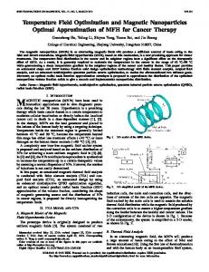
Results for lmrvl grating: Based on this conclusion, it is apparent that for the grating to operate correctly in response to the megahertz acoustic field, the grating length should be made smaller than half the acoustic wavelength in fused quartz. To demonstrate this, we took a standard Smm grating and removed small pieces of it from one end until = lmm of grating was remaining. As each piece was removed, we recorded the system response to the ultrasonic field and noted a dramatic decrease in the homodyne signal along with more symmetric side-band magnitudes. Because of the results of Fig. 2 (top), however, it is apparent that this shortened grating on its own cannot be used as a high frequency probe. The fibre must be desensitised to the acoustical field. This we did by jacketing the fibre with PVC sleeving (diameter < 1mm) such that only the linm grating at the end of the fibre was exposed to the field. The results of a longitudinal scan and a lateral scan of the acoustic focal spot are shown in Fig. 2 (bottom left) and Fig. 2 (bottom right), respectively. This data compares favourably with the diameter of the main diffraction maximum of the transducer, although there i s evidence of small scattering effects which we comment on shortly. Fig. 3 (right) shows the detected magnitude of one of the side-bands (normalised to its corresponding carrier signal) as a function of acoustical pressure incident on the grating. It is clear that the system response is linear and (for this probe) we determined a noise limited pressure resolution of 4.5 x l V 3 a t d dHZ.
the sleeving [5]),then it will be possible to multiplex FBGs onto the same fibre with little or no acoustic cross-talk. 0 IEE 1998 30 March 1998 Electronics Letters Online No: 19980795 N.E. Fisher, D.J. Webb, C.N. Pannell and D.A. Jackson (Applied Optics Group, The University, Canterbury, Kent, CT2 7NR, United Kingdomj L.R. Gavrilov and J.W.. Hand (Radiological Sciences Unit, Hcinzmersnzitlz Hospital, Du Cane Road, London, WIZ OHS, United Kingdom) L. Zhang and I. Bennion (Photonics Research Group, Department of Electronic Engineering, Aston University, Birmingham, B4 7ET, United Kingdom)
References 1 2
3 4
5
6
0
1
2
pressure,atm ;656131
Fig. 3 Pressure dependence of side-band and wavelength dependence oj”
hack-reflected light with wafer temperature Right: pressure dependence of side-band Left: wavelength dependence of back-reflected light with water temperature
Finally, since temperature-induced wavelength shifts occupy a very low frequency range compared to the strain signals of interest, it is straight-forward to decouple the two effects and measure both simultaneously: shown in Fig. 3 (left) are the wavelengths of the light back-reflected from the grating with water temperature. For convenience, we used an optical spectrum analyser and applied centroid-fitting to the spectra, to determine these shifts. In this case, a resolution of = 0.3”C was found. For a practical system, well-known interferometric techniques may be used [6]. Conclusions: We have demonstrated that a short FBG may act as a megahertz hydrophone and temperature sensor. However: (i) By shortening the grating we have reduced its reflectivity (in this case by a factor of over 150) and hence limited its resolution. For high power ablative hyperthermia, our resolution is probably sufficient. For conventional therapeutic applications this may not be so. Gratings < lmm but with 90% reflectivity can be manufactured. Hence, we anticipate a significant improvement using such gratings. (ii) Based on our model, the length of the grating sets an upper limit on the incident acoustic frequency which may be measured. Fortunately, in most medical applications, frequencies of 5OOkHz to 4MHz- are used whch implies that the FBG lengths should be I 0.5” for the highest frequency. Again, such lengths are available. (iii) We observed some evidence of scattering of the acoustical field due to the finite size of the sleeving. More sophisticated techniques for desensitisation entailing multiple coatings may alleviate this problem. In addition, if these coatings significantly attenuate the acoustic modes in the fibre (as we found using
1140
FIELD. S.B . and HAND, J W. (Ed.): ‘An introduction to the practical aspects of clinical hyperthermia’ (Taylor and Francis, London) KNuDSEN, s., and BLOTEKJAER,K.: ‘An ultrasonic fiber-optic hydrophone incorporating a push-pull Sagnac interferometer’, J. Lightwave Technol., 1994, 12, pp, 1696-1700 BEARD, P c., and MILLS, T N.: ‘Miniature optical fibre ultrasonic hydrophone using a Fabry-Perot polymer film interferometer’, Electron. Lett., 1997, 33, pp. 801-803 KERSEY. AD., BERKOFF, T.A , and MOREY, w.W.: ‘Fiber-optic Bragg grating sensor with drift compensated high-resolution interferometric wavelength-shift detection’, Opr. Lett., 1993, 18, pp. 72-74 FISHER, N E O’NEILL, S F., WEBB, D J., PANNELL, C.N , JACKSON, D.A., GAVRILOV, L.R , HAND, J w., ZHANG, L., and BENNION, J : ‘Response of in-fibre Bragg gratings to focused ultrasonic fields’. 12th Int. Conf. on Opt. Fiber Sensors, 1997, Vol. 16, pp. 190-193 RAO. Y.-J.: ‘In-fibre Bragg grating sensors’, Meas. Sei. Technol., 1997, 8, pp. 355-375
Dispersion-imbalancednonlinear optical loop mirror with lumped dispersive elements M. Matsumoto and T. Ohishi Self switching of optical pulses by a dispersion-imbalanced nonlinear optical fibre loop mirror is analysed. The loop mirror consists of an anomalous-dispersionfibre and a lumped dispersive element, such as a chrped fibre grating, whch is required to brake the symmetry of the loop for self-switching operation. It is shown that a higher switching contrast and a smaller switching power can be achleved compared with those for a standard nonlinear optical loop mirror.
Nonlinear optical fibre loop mirrors (NOLMs) [l], capable of handling ultra-short pulses, have been shown to be useful in a number of applications, such as soliton switching controlled by signal power [ 1, 21, all-optical demultiplexing [3], pedestal suppression of short pulses [4],and noise filtering in all-optical fibre communication systems [SI. The original NOLM uses a directional coupler with an uneven coupling ratio to break the symmetry of the loop, as is required for self-switching operation. Switching power can be lowered to some extent by the use of largely unbalanced couplers, but with the switching contrast degraded. Another approach to asymmetrise the loop is to insert an optical amplifier at one end of the loop [6]. The symmetry of the loop can also be broken in a truly passive manner by making the dispersion of the fibre loop asymmetric [7].A unique feature of this configuration is that continuous waves are completely reflected, irrespective of their amplitudes [8]. Recently, filtering of femtosecond pulses from a CW background and pulse shaping have been demonstrated by use of the dispersion-imbalanced nonlinear optical loop mirror (DINOLM) consisting of two pieces of fibres with different dispersions [8, 91. In this Letter, we analyse the switching properties of a DI-NOLM which consists of an anomalous-dispersion fibre and a lumped dispersive element located at one end of the fibre loop. Fig. 1 shows a schematic diagram of the DI-NOLM analysed here. We assume that each of the two dispersive elements A and B
ELECTRONICS LETTERS
28th May 1998
Vol. 34
No. I 1