Lateral view of the robot (left) and a bird eye's view (right). (a) DF. 4WD Robot with (b) Arduino ... Android applications. The orientation sensor obtains data by.
Ultrasonic-Sensor Deployment Strategies and Use of Smartphone Sensors for Mobile Robot Navigation in Indoor Environment Jongil Lim, SeokJu Lee, Girma Tewolde, Jaerock Kwon Electrical and Computer Engineering Kettering University Flint, MI, USA {lim7722, lee7704, gtewolde, jkwon}@kettering.edu Abstract-This paper presents deployment strategies of ultrasonic sensors and a way of using Smartphone sensors to help mobile robot navigation in indoor environments. There are critical needs for cost-effective, reliable, and fairly accurate solutions to meet the demands of indoor robotic applications. Ultrasonic sensors have been popular in detecting simple objects due to the low-cost and simplicity despite their limitations. We propose an efficient way of deployment of ultrasonic sensors for low-cost mobile robots. A Smartphone has many high performance sensors that can be utilized to navigate and localize mobile robots. The sensors include a camera, a gyroscope, and an accelerometer. We analyzed the use of orientation sensor of a Smartphone and compared its performance to a conventional approach. The comparison results were promising. The combination of the efficient way of the sensor deployment and the use of Smartphone sensors shows a possibility of developing a low-cost indoor mobile robotics platform for college education and robotics research laboratories. Index Terms— Mobile robot, Indoor navigation, Smartphone, Deployment of sensors
I.
INTRODUCTION
The demand of autonomous mobile robots has been increasing in our indoor daily lives. The recent commercial successes of vacuum cleaning robots show such high demands. Many improvements, however, are expected to have more commercial autonomous mobile robots in our indoor environment. Affordability of the robots is one of the most important factors while the quality tasks of mobile robots maintain. To keep their cost down, the robots do not have luxury to equip many expensive sensors such as a laser rangefinder, a 3D depth camera, and wheel encoders. One possible approach is to use Smartphones that are equipped with many high quality and high performance sensors since Smartphones are almost ubiquitous. The Smartphone sensors include an ambient light sensor, an accelerometer, temperature sensors, pressure sensors, and many more. Due to the reasons mentioned above researchers have been using Smartphones as part of mobile robots. Remote control systems of mobile robot were proposed using Bluetooth with
Smartphone [1][2]. Wired connection called IOIO [3] was used to connect a Smartphone to a mobile robot [4]. And a camera in the Smartphone was used to navigate the robot. Their main focuses were to remotely control the robots using a Smartphone. But the proposed system in this paper utilizes a Smartphone to sense a robot’s motion and to communicate with the mobile robot for autonomous navigation. External sensors such as a sonar sensor, a laser rangefinder, and a depth camera were used to detect objects in mobile robot navigation. A laser rangefinder or a Kinect camera was used to do tasks such as localization, environmental mapping or navigation [5][6]. Using expensive sensors were not our choice since we explore possibilities of developing a low-cost indoor robotics platform for robotics education in colleges and small-scale robotics research laboratories. To accomplish this goal, we developed an efficient sensor deployment strategy so that a minimum number of sensors were used. Our mobile robot can effectively detect objects in front of our mobile robot using only three ultrasonic sensors while it follows the wall. Two ultrasonic sensors were placed in a side of the mobile robot. With the sensors the mobile robot keeps a constant distance from the wall while it navigates. In this paper, in-depth analyses for deployment of the three front sensors and two side sensors will be presented. The experimental results show that three front sensors effectively detect facing objects while two side sensors detect the distance from the wall without interfering each other. Also we compared the rotation performance of the robot using Smartphone sensors with a conventional approach. The results were promising. The combination of the efficient way of the sensor deployment and the use of Smartphone sensors shows the feasibility of developing a low-cost indoor mobile robotics platform for robotics education in colleges and small-scale robotics research laboratories.
II.
RELATED WORKS
We will critically review a couple of methods in sensor deployments and a few of navigation techniques in this section. A. Deployments of Sensors to Detect Objects Yelamarthi, Sherbrook, Beckwith, Williams, and Lefief proposed a navigation method for a tour guide robot [7]. They used radio-frequency identification (RFID) to have a mobile robot navigate. Multiple infrared sensors and eight ultrasonic sensors were used to avoid obstacles. Ultrasonic sensors were located at 90°, 50°, 30°, 10°, -10°, -30°, -50°, and -90° on the front side, each sensor has an aperture of 15°. Choi, Lee, Lee, and Park proposed a RFID-based mobile robot localization method where RFID tags were evenly distributed in a space [8]. To detect obstacles, they used nine ultrasonic sensors that are installed with a 22.5 degree angle in front of the mobile robot. No quantitative analyses for sensors deployment were presented in [7][8]. We used a minimum number of ultrasonic sensors to detect obstacles in the proposed system. Only three ultrasonic sensors were installed on the front side with 45 degree angle apart in radial directions. Theoretical analyses and experimental evaluations for sensors deployment will be presented in Sec. IV. B. Navigations of Mobile Robots Three navigation techniques were analyzed for indoor robots in [9]: (a) optical wheel encoder “odometer-style” reading, (b) ultrasonic sensor readings, and (c) Wi-Fi signal strength received from a WLAN router. The wheels connected to the motor are attached to odometer (quadrature encoder) to measure wheel rotation that is used as feedback to the controller. An efficient localization scheme for an indoor mobile robot using RFID’s on the floor was presented in [10]. They also used an encoder to control wheels of a mobile robot. Using an encoder in a mobile robot has inherent problems where surface flatness, friction between wheels and ground, and remaining battery power affect the accuracy of the encoder. These factors contribute to the uncertainties in the control of the mobile robots. To remove the innate problems, we used orientation sensor readings of a Smartphone when the robot changes its direction. Consequently the robot was able to reduce errors in consecutive movements. III.
used. Ultrasonic sensors were used to avoid obstacles and to implement wall-following behavior. A Smartphone plays an essential role. Sensors in a Smartphone were used to measure rotation angles of the mobile robot. The Bluetooth module called HC-06 [13] is used for serial communication between a microcontroller and a Smartphone.
Fig. 1. Lateral view of the robot (left) and a bird eye’s view (right). (a) DF 4WD Robot with (b) Arduino MEGA, (c) DF Robot L298, (d) ultrasonic sensor HC-SR04, (f) Smartphone (LG Nexus 4) and (g) HC-06 Bluetooth module.
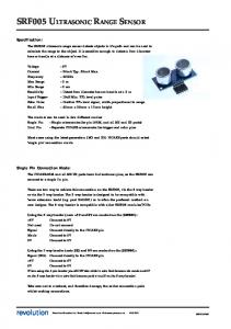
B. Sensor-Deployment Strategies Two sets of sensors in the robot. Lateral two sensors are used to maintain a constant distance from the wall. Three front sensors detect obstacles. Each of deployment strategies will be presented in the following sections. 1. Deployment of sensors for wall-following The mobile robot moves along the wall while maintaining the constant distance of 25 cm from the wall. Two ultrasonic sensors were attached to the side of the mobile robot to follow wall. The ranging distance of ultrasonic sensors is from 2 cm to 400 cm and the measuring angle of ultrasonic sensor is about 30 degree [14]. Ultrasonic sensors use the time difference between outgoing and incoming sound signals where there are chances that outgoing sound signals from other ultrasonic sensors come to another sensor. To avoid interference between two sensors, we used 14 cm that is the minimum required distance between the sensors not to have other sensor’s outgoing sound signal as shown in Fig. 2.
IMPLEMENTATION DETAILS
Hardware components including the robot chassis, motors, a Bluetooth module, ultrasonic sensors, and the Smartphone will be presented with design details of the robotics platform in this section. A. Hardware Design of the Mobile Robot The Atmega328 based Arduino MEGA Microcontroller is used as the brain to implement this system as in Fig. 1. A Bluetooth module and multiple sensors are controlled by the microcontroller. DF Robot 4WD platform [11] was used as the chassis of the robot. A motor controller based on L298 [12] was
Fig. 2. Efficient deployment of sensors
The minimum required distance was calculated by following equation (1).
W = 2×
H tan θ
(1)
This distance will be validated through the experiments described in the section IV. The experiment showed the calculated distance is accurate so that interference between two neighboring sensors was minimized. 2. Deployment of sensors for detecting objects To detect objects, we placed the three ultrasonic sensors in the front side. The angular distance between sensors is 45 degree. Simple shaped objects can be detected by these three sensors. To verify the effectiveness of the deployment, a series of experiments were conducted in eight different cases. Four cases in Fig. 3 are when the mobile robot moves toward an opened left-hinged door. So the robot sees empty space in its right side. Fig. 4 shows four cases where a right-hinged door is open in different angles. There are four cases with regard to sensor reading: sensor readings are valid from (a) the right sensor only, (b) the middle and the right sensor, (c) the middle sensor only, and (d) the left and the middle sensor. Due to the reflection of sound signals, some sensor readings were incorrect. We will present sensor readings in all these eight cases. With the experimental data we were able to conclude that sensor readings have sufficient information to maneuver the robot. See Fig. 3 and Fig. 4 for more details. The experimental results will be presented in the section IV. C. Rotation of Mobile Robot with Smartphone Smartphones come with several built-in sensors such as orientation, pressure, gyroscope, magnetometer, and accelerometer sensors etc.. For In this paper, we used Google's Nexus 4 Smartphone that is a development reference phone for Android applications. The orientation sensor obtains data by using a geomagnetic of a device field sensor in combination with an accelerometer of a device. Using these two sensors, the phone can generate orientation values in the three-dimensional space as shown in Fig. 5. Yaw is a degree of rotation around the z-axis. This is the angle between magnetic north and the device's y-axis. Pitch is a degree of rotation around the x axis. This value is positive when the positive z-axis rotates toward the positive y-axis, and it is negative when the positive z axis rotates toward the negative y-axis. Roll is a degree of rotation around the y-axis. This value is positive when the positive zaxis rotates toward the positive x-axis, and it is negative when the positive z-axis rotates toward the negative x-axis [14]. The proposed system used a data of yaw to measure the rotation of the mobile robot. The range of values is 0 degrees to 359 degrees. When the mobile robot is rotated, Arduino MEGA sends data of degree that is rotation angle to the Smartphone using Bluetooth. After the Smartphone stores the data received, the mobile robot begins to rotate until the mobile robot receives stop signal from the Smartphone.
(a)
(b)
(c) (d) Fig. 3. (a) detection of left sensor, (b) detection of middle and left sensor, (c) detection of middle sensor and (d) detection of left and middle sensor in a state that the side of a mobile robot is empty space
(a)
(b)
(c) (d) Fig. 4. (a) detection of left sensor, (b) detection of middle and left sensor, (c) detection of middle sensor and (d) detection of left and middle sensor in a state that the side of a mobile robot is closed
Fig. 5. Orientation sensors of a Smartphone. Pitch(X), Roll(Y) and Yaw(Z)
The Bluetooth module called HC-06 is used for communication between the Microcontroller and the Smartphone. The Arduino MEGA has one serial port (also known as a UART or USART port). It communicates on digital pins 0 (Rx) and 1 (Tx). Alternatively, the Arduino MEGA can also employ software serial communication by using general purpose digital pins. Using the serial communication protocol,
the Arduino MEGA and the Smartphone can communicate wirelessly via the Bluetooth module. Through this Bluetooth communication, the Smartphone is able to obtain degree of rotation from a mobile robot. EXPERIMENTAL RESULTS
Actual value
First sensor
Distance (cm)
Left
Our approaches described above have been implemented and validated using a mobile robotic platform with a Smartphone, a Bluetooth module, and ultrasonic sensors. We conducted experiments to validate the calculated minimum distance between two lateral sensors to maintain a constant distance (25 cm) from the wall. As show in Fig. 6, the two ultrasonic sensors read accurate values without interference from the other. The MSEs (see (2)) of two sensors (first sensor: about 0.08333 and second sensor: about 0.1666) were close to 0 indicating the sensor readings were accurate and no interference was found between each other.
Middle
Right
200
0
(a) Left
Distance (cm)
IV.
the right sensor read incorrect and irregular distance values in Fig. 8 (c) and (d) cases. We suspected the interference between sensors were the reason of the intermittent errors.
Middle
Right
100
0
(b)
Second sensor Left Distance (cm)
Distance (cm)
30 20 10
0
(c)
Fig. 6. Distance measurements of two laterally installed ultrasonic sensors. Two sensors were installed in 14 cm distance from each other as shown in Fig. 2
(2)
Fig. 7 and Fig. 8 show experimental results of distance measurement of three ultrasonic sensors in the front. Refer to Fig. 3 and Fig. 4 to see the sensor deployment. First we measured three ultrasonic sensors at the same time. We measured the distance between the obstacle and the mobile robot as the mobile robot moves toward obstacle by about 25 cm. The sensor readings in Fig. 7 and Fig. 8 were averaged from five trials. In Fig. 7 (a), (b), (c) and (d), objects were detected by only right (green) sensor, right (green) and middle (red) sensor, middle (red) sensor, and middle (red) and left sensor (blue) in environment respectively (see in Fig. 3). The four cases in Fig. 7 show that the ultrasonic sensors measured correct distances in most cases. But wrong measurements took place intermittently especially in Fig. 7 (d). The three ultrasonic sensors measured distance for the four cases as shown in Fig. 4 (see Fig. 8 (a), (b), (c) and (d)). Fig. 8 (a) and (b) show ultrasonic sensors obtained correct values. But
Left Distance (cm)
1 n ( Expected i − Sensori ) 2 ∑ n i =1
Right
200
0
MSE =
Middle
Middle
Right
200
0
(d)
Fig. 7. Distance measurements of three ultrasonic sensors that are placed in front of mobile robot when the door is left-hinged so that there is open space in the right side of the robot. The four cases are as shown in Fig. 3.
To address the problem where irregular values are read from three ultrasonic sensors, we alternated sensor readings from one to another sensor with 20-millisecond interval. As shown in Fig. 9 and 10, incorrect or irregular sensor readings for measuring distance were reduced. The right sensor still occasionally read incorrect values in Fig. 10 (c) and (d). However, this problem does not affect to detect obstacles, because the data of right sensor read larger data than other correct data. Fig. 11 and 12 show the results of rotation and navigation of a mobile robot using an orientation sensor of a Smartphone and encoder respectively. Comparisons of experimental results of robot’s rotation using two methods are presented in Fig. 11. The bars in the figure are the average values from five trials. Fig. 11 shows rotation angles are closer to the true angles when the
Distance (cm)
Distance (cm) Distance (cm)
Right
0 (a)
Middle
Right
200
0 (b)
Left
Middle
Right
200
0 (c)
0 Left
(a)
Middle
Right
100
0 (b)
Left Distance (cm)
Right
50
Left
Middle
Right
0 (c)
Middle
Right
200
0
(d) Fig. 8. Distance measurements of three ultrasonic sensors that are placed in front of mobile robot when the door is right-hinged. The four cases are as shown in Fig. 4.
Middle
Right
200
0
(d) Fig. 9. Distance measurements of three ultrasonic sensors that are placed in front of the mobile robot when the door is left-hinged so that there is open space in the right side of the robot. The four cases are as shown in Fig. 3. Each sensor alternately measures distance with 20 ms interval to reduce interference from other sensors.
V.
200
Left Distance (cm)
Middle
Middle
200
Left
Distance (cm)
Distance (cm)
Left
Left
Distance (cm)
orientation sensor was used (left figure) than when an encoder was used (right figure). Also the fact that the smaller standard deviations in the left figure than those of the right figure shows that using the Smartphone sensor allows us to obtain consistent outputs. Fig. 12 shows path trajectories of a mobile robot that navigates using two methods respectively. The size of the arena is 3 m by 5 m. The mobile robot reaches the destination through the rotation of eight times from the start to the destination point. The black line shows true trajectory. The experimental results show the mobile robot using the sensor in a Smartphone is closer than using an encoder to the destination as shown in Fig. 12. Furthermore, the experimental results of Fig. 12 (a), five destination points are distributed close. Meanwhile, the experimental results of Fig. 12 (b), five destination points are distributed widely. As a result, using a Smartphone sensor is easier than using an encoder to predict the next position.
CONCLUSION
In this paper, we presented sensor deployment strategies and a navigation method of a mobile robot using an orientation sensor of a Smartphone. The proposed approaches were validated with corresponding experimental results. Efficiently deployed sensors did their job with a minimum number of sensors. Using an orientation sensor of a Smartphone showed better performance in rotating robot than using an encoder. This approach showed robustness in the conditions where friction of surface is not consistent. Also it does not require the robot to equip expensive sensors. The experimental results in this paper showed that we can obtain accurate sensor readings and the cost-effectiveness using Smartphone and minimum extra sensors. The combination of the efficient way of the sensor deployment and the use of Smartphone sensors shows a possibility of developing a low-cost indoor robotics platform for college education and robotics research laboratories.
Distance (cm)
Left
0 (a)
Distance (cm)
Middle
Right
200
0 (b)
Left Distance (cm)
Right
100
Left
Middle
Right
Fig. 12. Path trajectories (a) using a sensor of a Smartphone and (b) using encoder. Five experiments were conducted for each case. The bold black line is the true trajectory.
REFERENCES
200 [1]
0 [2]
(c)
Left Distance (cm)
Middle
Middle
Right
[5]
200
[6]
0
(d) Fig. 10. Distance measurements of three ultrasonic sensors that are placed in front of the mobile robot when the door is right-hinged. The four cases are as shown in Fig. 4. Each sensor alternately measures distance with 20 ms interval to reduce interference from other sensors.
Smartphone
Encoder
360
360
315
315
270
270
225 180 135
Degree(◦)
Degree(◦)
[3] [4]
225
[6] [7]
[8]
[9] [10]
180 135
90
90
45
45
0
0
Fig. 11. Comparison of rotation performances between a rotation sensor of the Smartphone (left) and an encoder (right). Note that the values in x-axis are same as those in y-axis.
[11] [12] [13] [14] [15]
Yong-Ho Seo, Seong-sin Kwak, and Tae-kyu Yang, “Mobile Robot Control Using smart Phone and Its Performance Evaluation”, ACN 2011, CCIS 199, pp. 362–369, 2011 Andre Guilherme Nogueira Coelho dos Santos, “Autonomous Mobile Robot Navigation using Smartphones” “IOIO Documentation”, https://github.com/ytai/ioio/wiki Nolan Hergert, William Keyes, and Chao Wang, “Smartphone-based Mobile Robot navigation” Frantisek Duchon, Martin Dekan, Ladislav Jurisica and Anton Vitko, "Some Applications of Laser Rangefinder in Mobile Robotics", CEAI, Vol.14, No.2, pp. 50-57, 2012 Joao Cunha, Eurico Pedrosa, Cristovao Cruz, Antonio J.R. Neves and Nuno Lau, "Using a Depth Camera for Indoor Robot Localization and Navigation." A. Tsalatsanis, K. Valavanis and N. Tsourveloudis, “Mobile robot Navigation Using Sonar and Range Measurements from Uncalibrated Cameras”, J Intell Robot Syst (2007) 48:253–284 Kumar Yelamarthi, Stephen Sherbrook, Jonathan Beckwith, Matt Williams and Rober Lefief, “An RFID Based Autonomous Indoor Tour Guide Robot”, Circuits and Systems (MWSCAS), 2012 IEEE 55th International Midwest Symposium Byoung-Suk Choi, Joon-Woo Lee, Ju-Jang Lee and Kyoung-Taik Park, “A Hierarchical Algorithm for Indoor Mobile Robot Localization Using RFID Sensor Fusion”, IEEE TRANSACTIONS ON INDUSTRIAL ELECTRONICS, VOL. 58, NO. 6, JUNE 2011 Fadi N. Sibai, Hassane Trigui, Pablo Carrasco Zanini and Anwar R. AlOdail, “Evaluation of Indoor Mobile Robot Localization Techniques”, Journal of Emerging Trends in Computing and Information Sciences Byoung Suk Choi, Jae Mu Yun and Jang Myung Lee, “An Efficient Localization Scheme for an Indoor Mobile Robot”, SICE Annual Conference 2005 in Okayama, August 8-10, 2005 Okayama University, Japan “Pirate-4WD Mobile Platform” http://www.dfrobot.com/index.php?route =product/product&product_id=97#.U1Ctx_ldV0M “DFRobot L298 DC motor driver shield”, http://elesson.tc.edu.tw/md221/pluginfile.php/4241/mod_page/content/ 10/L298_Motor_Shield_Manual.pdf “HC-06 Manual”, http://www.exp-tech.de/service/datasheet/HC-SerialBluetooth-Products.pdf “Product User’s Manual – HC-SR04 Ultrasonic Sensor” “Android developers”, http://developer.android.com/index.html