Noname manuscript No. (will be inserted by the editor)
UML Behavioral Consistency Checking using Instantiable Petri Nets Yann Thierry-Mieg · Lom-Messan Hillah
the date of receipt and acceptance should be inserted later
Abstract 1 Model-Driven Engineering (MDE) development methods are gaining increasing attention from industry. In MDE, the model is the primary artifact and serves several goals among which code generation, requirements traceability, and model-based testing. MDE thus enables cost-effective building of models vs. direct coding of an application. Thus model-based formal verification of behavioral consistency is desirable as it helps improve model quality. Our approach is based on translation of a UML model to Instantiable Petri Nets (IPN). This formalism is based on the semantics of Petri nets, but introduces the concepts of type and instance. This allows to accurately capture these concepts in UML models. IPN support hierarchical descriptions natively, and use the notion of transition synchronization for composition of behaviors. This is a general and powerful mechanism borrowed from process algebra. We show that IPN allow to adequately address the challenges of translation from UML for analysis purposes. The approach has been implemented and experimental results are presented.
1 Introduction The complexity of software systems and their parallel, distributed and heterogeneous nature raises many challenges when trying to ensure their correctness. In this respect, model checking is a formal verification technique which promises to automatically check whether a system satisfies some stated properties. Model checking is an active research domain [CES07], and many techniques have been developed to face the stateUniversité P. & M. Curie, LIP6 - CNRS UMR 7606 - 4 Place Jussieu, Paris, France E-mail:
[email protected] 1 This work has been partially supported by the ModelPlex European integrated project FP6-IP 034081 (Modeling Solutions for Complex Systems)
space explosion problem such as symbolic methods, partial order and symmetry exploitation, and abstraction methods [DH07]. However, adoption by industry remains limited to niche applications, partly because the formalisms used for model checking purposes are considered too difficult to be used by lambda developers. In contrast, Model-Driven Engineering (MDE) techniques are gaining attention since machinereadable specifications (models) are more precise, less error prone, can be processed by automated tools, and can allow by code generation to be less dependent on fast evolving technologies [HT06]. For the formal verification community, this offers the possibility of defining model checking based verification as one of many services on industrial UML models. It thus helps adoption of these formal techniques into mainstream software development methods. In this paper we present a translation based approach using (parts of) UML [OMG07] as source and Instantiable Petri Nets (IPN) as target, to enable formal verification. IPN is a formalism defined expressly for this purpose; it is not meant to be used as a front-end modeling language but rather as a powerful back-end verification formalism. The semantics and concepts are thus kept simple. We show that IPN are adequate to support the introduction of model checking in an MDE process. The approach is implemented in a prototype tool called BCC: Behavioral Consistency Checker. O UTLINE : Section 2 compares this work to some similar approaches based on translation of UML to formal notations. Section 3 defines the IPN formalism. Section 4 then shows how we use IPN to capture the semantics of UML behavioral models. Section 5 explains how we use the IPN specifications produced to verify several relevant consistency properties. Section 6 reports on the tool Behavioral Consistency Checker (BCC) that integrates these concepts to offer
2
compiler-style warnings to UML behavioral diagram users. We finally conclude and sketch some perspectives. 2 Related Work UML is a standard defined using a meta-modeling approach to establish the concepts of the various diagrams, and plain English to describe dynamic aspects of the specification. UML2 has introduced an important refactoring of the description of actions and behaviors, which allows to describe the behavioral diagrams (activity, state machine and interaction diagrams) using a common base. The semantics of a UML2 model is thus more precise than in UML 1.x. But socalled semantic variation points are deliberately left in the standard, to help UML fit all possible application fields of software engineering. The semantics of UML thus remains imprecise and subject to interpretation. The idea of providing a formal semantics to (at least parts) of the UML by translation to a more formal description is widely used [BCD+ 07]; it allows to use the UML as a (relatively) user friendly graphical environment and exploit the existing formal verification techniques and tools without redeveloping them specifically for the UML. It also is compatible with the ideas of Model-Driven Engineering (MDE) in which the model is the central artifact, and translations from the model to other artifacts (code, tests. . . ) with specific goals in mind is the norm. One of the challenges when defining such a translation is to handle the composition of parts of a behavior, defined using different types of diagrams. This touches on the problem of consistency among UML diagrams of a given system: although structural consistency rules are defined (using OCL) and can be checked mostly syntactically, the multiple viewpoints offered by the UML induce the possibility of defining incompatible behaviors quite easily. Given the wealth of work on translation of UML models for analysis purposes, we focus here on a few propositions which are the most similar to this work, particularly those targeting dialects of Petri nets in the translation. Merseguer et al. have done an important work ([CM06] gives an overview) on translation of the UML to labeled generalized stochastic Petri nets (LGSPN) for performance analysis purposes. Tool support is provided through the ArgoSPE tool set and the model checker GreatSPN. This work is perhaps the closest to ours because the semantics used to compose the LGSPN is based on synchronizations, like in our IPN. However, that work is centered on performance evaluation rather than consistency checking. Moreover LGSPN do not allow hierarchical compositions. The work of Eshuis et. al [Esh06] also gives a formal semantics to activity diagrams through translation to workflow nets, and more recently to NuSMV. However they concentrate mainly on a subset of activity diagrams compatible
with UML 1.5, and do not handle hierarchy of the description. Shatz et al. have also done a large body of work [HS06, YS06] on formalization of UML semantics, mostly centered on state charts, that uses Petri nets as translation target. The focus of that work is in correctly capturing the full run to completion semantics of UML state machines. It thus does not address the problem of inter diagram consistency checking. Engels et al. [EHK01] have elaborated a formalization framework based on CSP as semantic domain. This work is mainly focused on protocol statecharts of UML 1.4. It does not handle hierarchy as to enable scalability in the specification. Overall the main originality of this work is in the composition mechanisms used and the fact we natively support hierarchy instead of requiring a flattening of the representation, which leads to scalability issues. We also present an implementation in section 6.
3 Definitions In this section we formally define Instantiable Petri Nets (IPN). IPN explicitly support the concepts of type and instance that allow to adequately match the structure of high-level models designed with UML. They also allow to reuse parts of a model in various scenarios, and offer good scale up properties to handle large and complex specifications. Finally, since instances of a type share a common definition, they allow to capture internal regularity or symmetries of a system, which can be exploited for model checking. IPN explicitly support a compositional definition based on the notion of synchronizations. A wide corpus of theoretical [GMF07] and empirical [CLM07] results (introduced by process algebra such as CSP [Mil99], up to applicability to probabilistic systems [DF96]) show that this mode of composition is favorable to better compositional verification algorithms. We first define a general composition framework (in 3.1) called Instantiable Transition Systems (ITS), and then reify the definition using Petri nets (in 3.2) as elementary building block.
3.1 Instantiable Transition System The generic definition of an Instantiable Transition System (ITS) builds upon the notion of model type and instance as well as a composition mechanism based solely on transition synchronization (no explicit shared memory or channel).
3
Notations: Bag(A) denotes a multiset over a set A, and for a multiset τ ∈ Bag(A) and an element a ∈ A, we denote by |a|τ the number of occurrences of a in τ. We note tuple.X,tuple.Y . . . the element X (resp. Y . . . ) of a tuple tuple = hX,Y i. Definition 1 An ITS TYPE is a tuple type = hS, LabeledStates, T,V, Locals, Successorsi: – S is a set of states; – LabeledStates ⊆ S is a finite subset of states which bear a label; – T is a finite set of transitions; – V : T 7→ {public,private} is a function assigning a visibility to each transition; – Locals : S 7→ 2S is the local successors function. It returns states reachable by firing private transitions. – Successors : S × Bag(T ) 7→ 2S is the transition function. A multiset of transitions τ ∈ Bag(T ) is said to be simul/ By taneously enabled in state s if Successors(s, τ) 6= 0. / = {s}, thus the empty definition, ∀s ∈ S, Successors(s, 0) set of transitions represents the identity transition function. Let Types denote a set of ITS types. An ITS INSTANCE i is defined by its ITS type, noted type(i) ∈ Types. An ITS instance i may be associated to a state s ∈ type(i).S. We use the terminology: “assign a state s to instance i”. Definition 2 An ITS SCENARIO is a tuple hTypes, main, s0 i: – Types is a set of ITS type definitions, – main is an ITS instance such that type(main) ∈ Types, that defines the container of the model, – s0 ∈ type(main).LabeledStates is the initial state assigned to the “main” instance. We now define a specific ITS type to offer minimal support for the composition of ITS instances. Let I designate a set of ITS instances. Let SyncMapI designate the set of mappings from instances i ∈ I to a multiset of public transitions of type(i). More precisely, let interface(i) = {t ∈ type(i).T | type(i).V (t) = public}; s ∈ SyncMapI =⇒ ∀i ∈ I, s(i) ∈ Bag(interface(i)). Let the sum ⊕ : SyncMapI × SyncMapI 7→ SyncMapI be defined as: s0 = s0 ⊕s1 ⇐⇒ ∀i ∈ I, s0 (i) = s0 (i)]s1 (i) where ] designates the standard sum of multisets. Intuitively, SyncMapI represents a synchronization of public transitions of the set I of subcomponents. Definition 3 A COMPOSITE ITS TYPE is a tuple C = hI, T,CS, LabeledStates,V, , Locals, Successorsi: – I is a finite set of ITS instances, said to be contained by C. We further require that the type of each ITS instance i ∈ I preexists when defining these instances, in order to prevent circular or recursive type definitions.
– T ⊂ SyncMapI is the finite set of transitions called synchronizations; – CS ≡ S is a set of composite states, such that a state cs ∈ CS assigns to each instance i ∈ I a state cs(i) ∈ type(i).S – LabeledStates ⊆ CS is a finite subset of states which bear a label, where cs ∈ LabeledStates =⇒ ∀i ∈ I, cs(i) ∈ type(i).LabeledStates – V : T 7→ {public,private} is a function assigning a visibility to each synchronization – Locals : The set of local successors of a state cs is defined by: cs0 ∈ Locals(cs) ⇐⇒ (∃i ∈ I, cs0 (i) ∈ type(i).Locals(cs(i)) ∧∀ j ∈ I, j 6= i, cs0 ( j) = cs( j))∨ (∃t ∈ T,V (t) =private, cs0 ∈ Successors(cs, {t})). – Successors : The set of successors of a state cs by a multiset τ ∈ Bag(T ) is defined by cs0 ∈ Successors(cs, τ) L ⇐⇒ cs0 (i) ∈ Successors(cs(i), ( t∈τ t)(i)). Definition 4 ITS SEMANTICS A state s0 is reachable by a scenario R ⇐⇒ ∃S1 , ..Sn ⊂ type(R .main).Sn s.t. S1 = {R .s0 } ∧ s0 ∈ Sn S ∧∀i ∈ [2..n], Si = s∈Si−1 type(R .main).Locals(s). The system level transition relation is thus defined to take into account the notion of transition visibility: public transitions are only enabled through an external synchronization, and not in isolation (i.e. locally to an instance). ITS have simple semantics, strongly based on the notion of transition synchronization. Limiting the composition semantics in this way is favorable to using various verification algorithms that exploit compositional verification [CLM07, DF96] and locality of actions. The definition of the successor function as returning a set of successors (and not a single successor state) offers good generality, and allows in particular to capture non-deterministic transition relations. This feature has been used when defining more complex ITS types than those presented in this paper.
3.2 Instantiable Petri Nets The ITS definition is generic, and is extensible by providing new sorts of types that respect the definition of ITS type given above. Instantiable Petri Nets (IPN) are built using standard Petri nets as elementary type in an ITS definition as well as the composite ITS type. Thus IPN integrate the notion of ITS type and instance as well as a composition mechanism based solely on transition synchronization (no place fusion). Definition 5 An ELEMENTARY IPN TYPE is a tuple hP, T, Pre, Post, M, LabeledStates,V, Enable, Locals, Successorsi: – P is a finite set of places; – T is a finite set of elementary transitions;
4
– Pre and Post : P × T 7→ N are the pre and post functions labeling the arcs; – M ≡ S is a set of states called markings, such that each marking m of M is of the form m : P 7→ N; – LabeledStates ⊆ M is a finite subset of markings which bear a label; – V : T 7→ {public,private} is a function assigning a visibility to each transition; – Locals : The set of local successors of a state s is defined by s0 ∈ Locals(s) ⇐⇒ ∃t ∈ T,V (t) =private, cs0 ∈ Successors(cs, {t}). – Enable : Bag(T ) 7→ B: a multiset of transitions τ is simultaneously enabled in a marking m if for each place p, the condition ∑t∈τ |t|τ · Pre(p,t) ≤ m(p) holds; – Successors: the simultaneous firing of a multiset of transitions τ in a marking m leads to the empty set if Enable(m, τ) = false. Otherwise it leads to the set {m0 } where m0 is defined by ∀p ∈ P, m0 (p) = m(p) + ∑t∈τ |t|τ · (Post(p,t) − Pre(p,t)).
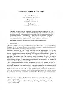
4.1 Mapping UML Behaviors to elementary IPN We use in this paper UML activity diagrams. A similar approach can be applied to other UML diagrams that represent a Behavior. The essential characteristic of a behavior is that it begins with an occurrence of a start event and ends with a termination event occurrence (UML Superstructure, section 13, p.419 [OMG07]). The transformation is based on a set of patterns of transformation. The principle consists in building one IPN type per diagram of the UML specification. These types will then be instantiated and assembled according to various verification scenarios. Hence for each activity diagram we build an elementary IPN type. We first apply the translation rules for the various types of nodes of the UML activity diagram, using the patterns described in figure 1. UML name
UML graphics
IPN pattern t
a
a
t
Connections in : N/A out : a
initial
IPN EXPRESSIVENESS: is equivalent to standard Petri nets. Indeed, IPN can be “flattened” to an equivalent Petri net using a simple algorithm. The algorithm simply consists in creating places in the flattened net using a fully qualified naming scheme : e.g. main.i2.i1.p1 for the place p1 of the IPN instance i1 of the composite IPN instance i2 which is contained by the main instance. Similarly, a transition is created for each private transition t of the “main” instance, by fusing the definition of the transitions of t(i). Additional transitions are added for each private transition of contained instances in the composite case. This algorithm is applied recursively to contained instances until elementary net types are reached. IPN CONCISENESS: is however potentially exponentially better than Petri nets. Indeed, the flattening procedure duplicates transitions for each instance of a net type. Consider an IPN instance of Mn , where the type Mn is recursively built as a composition of two instances of a net type Mn−1 . For each place (resp. transition) of the elementary IPN M0 , 2n places (resp. transitions) will be produced in the flattened representation. However, the IPN representation of the model stays linear in size with respect to n.
4 Mapping UML to IPN We show in this section how using IPN allows to comfortably map the concepts of UML semantics to IPN. In this example, each activity diagram is mapped to an elementary IPN type. The parts are then assembled following the structure given by class diagrams.
final action
a
sendEvent
o.send
recvEvent
recv call(a)
callBehavior IPN graphical notation
place
in : a out : N/A
a
in : a out : a
a
t
b
in : a out : b
a
t
b
in : a out : b
a
t
b
private transition
public transition
t’
c
in : a out : c
arc
Fig. 1 Translation rules for nodes of UML2 activity diagrams.
P LACES : Each node gives rise to one or more places and zero or more public transitions. The most complex case is the callBehavior pattern where the place b represents a state where we are waiting for the called behavior to complete. We keep track during the application of this transformation of the in and out places generated for each UML object. After this first pass all places of the resulting IPN have been produced; each control flow has a source (the “out” place of the source activity) or a destination (the “in” place of the target activity) or both. An additional case not represented on this figure (but used in the example see fig. 4) arises for control flows that link two control nodes (e.g. merge to fork): we produce an additional place for these edges that acts as both as source and destination in the translation. I NTERFACE : The public transitions produced are meant to be synchronized with other diagrams: the transition labeled t of the initial pattern is meant to be synchronized with the transition t of the callBehavior pattern. Similarly, the transition t of the final pattern is meant to be synchronized with the transition t 0 of the callBehavior pattern. Transition
5
t of the sendEvent pattern is meant to be synchronized with the appropriate corresponding transition t of the recvEvent pattern of the receiving object. S TATES : We additionally define two labeled states for each diagram, active which assigns one token to the place corresponding to the UML initial node, and passive (the default) in which all places are initially empty. T RANSITIONS : We then translate the control flows and control nodes of the UML activity diagram, using the patterns described in figure 2. In these patterns, the activities noted a, b and c are just placeholders for the actual nodes that the edges connect to: the translation pattern is centered on a control node, and queries the control flows that link to it to obtain the appropriate source or target place that was defined in the first translation step. UML name
UML graphics
a
act Order [order rejected] ReceiveOrder
HandlePayment
act HandlePayment
Send Invoice
Make Payment
Accept Payment
Fig. 3 An example adapted from the UML standard, p.357.
t
b.in
b
b
a.out
CloseOrder
int1 FillOrder
Order
c.in
init
c
accept a.out
a
reject
b.in
t
a
Join
Ship Order
FillOrder
ReceiveOrder
Fork
CloseOrder
[order accepted]
IPN pattern a.out
Control Flow
graphically depicted in figure 4. Names and graphical layout have been added to the figure to help the reader track the transformation.
b.out
b
a.out
c.in
int2 callPayment
call
endPayment
end
b
Decision
t
b
t c.in
c
SendInvoice
AcceptPayment
t’ a.out
a
final end
c.in c
MakePayment
init call
a
Merge
b.in
Payment
c
t
b.out t’
IPN graphical notation
place
private transition
public transition
arc
Fig. 4 IPN elementary net types obtained by application of the translation rules.
Fig. 2 Translation rules for edges of UML2 activity diagrams.
These patterns are mostly straightforward Petri net interpretations of UML semantics, so we hope a reader familiar with both UML and Petri nets will understand these translation patterns without further ado. All the transitions produced in this phase have private visibility: interaction with other diagrams happens within nodes in activity diagrams. This is to be contrasted with the reactive semantics of UML state-machines, in which edges are the main point of interaction with other diagrams.
4.2 Application to an example Figure 3 presents a small example that describes an order and shipping process. It contains many of the UML features our translation supports. The action HandlePayment of the “Order” activity is a CallBehavior action that refers to the behavior described by the “HandlePayment” activity. The translation yields one elementary net for each activity,
4.3 Composing Diagrams The first translation step has allowed to build an IPN type for each diagram of the original specification. Additionally we have built a trace that gives for each UML behavior of the original specification the name of the IPN type produced and the set of links to other behaviors that need to be resolved. I NTER - DIAGRAM LINKS: The information contained in a link depends on its nature : – For send event type links, we have the target UML object instance and the name of the transition that sends this event (i.e. noted t in Fig.1). – For receive event type links, we have the event and the name of the reception transition (i.e. noted t in Fig.1) – For CallBehavior actions, we have the target UML Behavior and the name of the transitions corresponding to the call and behavior end (i.e. t and t 0 in Fig.1)
6
– Finally for CallOperation actions, we have the target operation name and the target UML object instance as well as the names of the call/return transitions of the IPN. We then incrementally build more complex scenarios by using different linking strategies. D IAGRAMS IN ISOLATION: The most basic strategy consists in building “isolated” behaviors from each behavior (see Fig.5 top). For a net type n representing a behavior b, we build isolated(b)as a composite type containing a single instance i of type n, two public transitions call and end that synchronize to i.call and i.end respectively, and one private transition synchronizing to each transition of i mentioned in the links. The public link transitions corresponding to interactions with the environment are made private in the isolated type, thus enabled at will provided local conditions allow it.The states active and passive are also defined, as associating the corresponding state to i. The isolated construction thus allows to control the consistency of a diagram in an uncontrolled environment setting.
types corresponding to the activities and “export” the public transitions of the nested activity diagrams. In particular the transitions that allow to start (initial node pattern) and detect the end (final node pattern) of an operation are made visible to connect to CallBehavior of other objects. When the class contains objects by composition, the corresponding IPN types are instantiated. This gives us a context necessary to determine the target of a CallBehavior or SendEvent action.
5 Defining Consistency Checks One of the main issues when defining properties to verify is that the user (at the UML level) should not explicitly manipulate the formalisms used to specify properties, typically LTL or CTL formulae. This limits the scope of what we can verify, but as we show here, many useful checks can already be defined without user intervention.
Isolated(Order)
5.1 Verifying Properties call call
i:Order
end
callPay endPay
end Connected(Order,1)
call call
i:Order
end
callPay
call
endPay
end
p:Isolated(Payment)
end
instance
i:Order
private synchronization
public synchronization
synchronization parts
Fig. 5 Composite IPN types produced to analyze composed behaviors
C OMPOSING DIAGRAMS: Inductively, we can then build types connected(b, k) (see Fig.5 bottom) corresponding to connections resolved up to depth k, where isolated(b) is equivalent to connected(b, 0). The type connected(b, k + 1) contains one instance i of type n (representing b) and for each behavior b0 mentioned as a link target, an instance of the connected(b0 , k) net type. The call and end transitions are again exported with public visibility, and the links are actually resolved by synchronizing the link transitions of n with the call and receive of the depth k behavior instances. UML behaviors can be associated to classifiers or operations. The main use case we have considered is a model where operations may be defined by activity diagrams. Class diagrams are exploited in the following way: when operations of the class are associated with activity diagrams, we construct an IPN type that contains instances of the IPN
A model-independent property can be defined regardless of the model instance considered. Typical examples include absence of deadlocks or livelocks, boundedness. . . These are the easiest to handle as they naturally do not require user input. We first run a structural bounds computation tool (based on [Mur89]), that produces for each place its structural min/max bounds. This tool scales very well as the check is structural so the complexity is linked to the number of places and transitions of the specification, and not to the state space size. This tool allows to detect: – dead code: [0..0] bounded places indicate unreachable model elements. The interpretation here is that the model element associated to the place is either unreachable (logical design error) or disconnected from the rest of the diagram (modeling bug). In practice, the second interpretation is often correct, as a common error due to the GUI of UML modeling tools is to delete elements from a diagram but not from the model; – unbounded behavior: if a place marking is bounded by +∞ this usually indicates a serious misuse of fork/join constructs. This error was actually raised several times in the models provided by industrial partners of ModelPlex. Neither testing, nor simulation tasks which were working with the same models correctly identified this issue. Simulation actually detected a choke point during performance evaluation and suggested attributing more resources to this faulty activity. Testing would need an infinite test sequence to correctly tag this problem.
7
When the previous check does not detect unbounded behavior, we can proceed to use model checking based tools for more advanced checks. At this stage we check for absence of deadlocks in the specification. Existence of deadlocks is tagged as an error. We also check for activity diagrams that their final state is reachable when the initial state is set to “active” (see section 4.1). This is tagged as an error if it is not verified. As described in the next subsection, these checks are executed incrementally first on each diagram in isolation, then progressively on more complex compositions of diagrams. The list of verification goals is extensible as we think of new checks interesting for the end-user.
5.2 Incremental and Compositional Verification When verifying IPN, we first run simple checks, using the elementary nets obtained from each diagram. We run the nets first synchronized with a controller net that allows each public transition to fire exactly once. Then we run it in an “uncontrolled environment” in which all public transitions can fire arbitrarily. Then we gradually compose the model with the other IPNs it should synchronize with, according to the UML model (CallBehavior...) and run the checks again. Note here that it is important that each UML object have its own net instance, although the behavior is the same for all objects of a given class. This is adequately captured by the notion of instantiation of IPN. Furthermore, when a specification contains several calls to an operation from different places, the synchronization semantics adequately handles these call instances, when a more simple schema based on transition fusion would fail. The synchronization on events is also appropriate to integrate the data from the diverse views offered by the UML. Any UML behavior (sequence diagrams, activity, state-machines) can be translated to an IPN thus offering a common semantic ground to compare the information contained in various diagrams. Synchronization of incompatible behaviors either produces deadlocks or unreachability of the place representing the final state. This approach allows to incrementally find deeper errors or problems. It intensively uses the definition of the model as a set of net types and a “main” instance, as the different scenarios are built as specific instantiations that reuse common definitions.
5.3 Conclusions on the Transformation We thus support the BasicActivities, IntermediateActivities and StructuredActivities packages of the standard, which means our tool handles UML compliance level 2 (see UML2
superstructure [OMG07] for definition of compliance levels). The weakness of this translation is in the non-determinism of decision nodes, and the absence of any data manipulation. While this may seem a severe restriction, in practice the diagrams we studied (within ModelPlex) were mostly annotated in plain text. They correspond to early phases of design where the logic of the control flow is the focus. Other diagrams we studied were obtained by translation from BPEL, a language for describing the workflow of a business process, where again data manipulation is not the focus. In any case, supporting code level annotations requires extending the standard with a tool specific profile, as the UML standard does not define any data types other than String, Boolean and UnlimitedNatural, or any concrete syntax for actions (e.g. arithmetic). The strength of the approach is that it preserves the modularity of the UML specification. Thanks to the concepts of IPN, a UML translation is quite easy to set up, and only one IPN type is produced per UML diagram. When considering several scenarios and a system composed of interacting objects, the fundamental notion of instantiation from objectorientation which is preserved in IPN allows to adequately reuse a model defined in parts. The semantics of IPN are sufficient to capture the concepts of UML behavioral diagrams (sequence, alternative, fork join and parallel behavior, synchronization on events, multiple instantiation. . . ).
6 Behavioral Consistency Checker Behavioral Consistency Checker (BCC), is a tool designed to transparently use formal model checking to provide behavioral consistency checks on UML specifications. Requirements on the tool include that it should need minimal user training, and that the underlying verification technology has to be transparent. To reach these aims, BCC uses UML diagrams as input, and produces easily understandable compilerstyle errors and warnings when consistency rules are violated. This tool was developed as a contribution to the European integrated project ModelPlex 2 (21 industrial and academic partners, 20 MA C, 36 months). Within the project, models produced by industrial use case providers are used for several other goals than just verification, such as code generation, requirements traceability and test generation. Thus the investment in the modeling effort is amortized, and any check we can implement that improves the quality of the models is valuable, as the approach is model-centric, and model quality is a goal in itself in this setting. BCC will be integrated in a “model-based simulation, verification and 2
http://www.modelplex.org
8
testing (SVT) workbench” that is one of the deliverables of the project. The tool is implementented in Java using the EMF framework to parse standard XMI UML models. The transformation is written entirely in Java, rather than using a model transformation engine such as ATL: we had non trivial traceability issues otherwise. Model-checking tools (written in C or C++) are run transparently on CPN-AMI model-checking platform [HHK+ 06]. Post-interpretation of verification results is again written in Java, using the transformation traces intensively. A prototype of the tool is available at http://move. lip6.fr/software/BCC/. It currently handles activity diagrams and a subset of state-machine diagrams. It will be completed by the end of ModelPlex (Sept. 2009). We are working on improved class and component diagram handling. Component diagrams allow to have a specific connection topology as the parts are class instances. We also work on a sequence diagram translation to IPN. It will allow to control that the sequences describing an expected behavior are indeed executable. Thus it is a means for the user of specifying model-specific properties to check.
7 Conclusion In this paper we presented an approach designed to help bridge the gap between industrial modeling languages such as UML and the world of formal methods. It builds upon the concepts introduced by model-driven engineering, namely translation from a multi-purpose modelling language, UML, to a formalism dedicated to a specific goal, here modelchecking. For this purpose, we have defined Instantiable Petri Nets, a formalism that can be seen as an abbreviation of standard Petri nets. It uses a formally defined concept of type and instance and a composition mechanism exclusively based on transition synchronization. We have shown how IPN are well adapted to capturing some important concepts of high level modeling languages through an example that translates UML2 activity diagrams to IPN. Furthermore, the reuse of models in various scenarios is directly supported. Finally, we have presented how IPN were concretely used within a tool called Behavioral Consistency Checker to help verify the correctness and inter-diagram consistency of UML diagrams. We are currently working on integrating other behavioral diagrams in our translation. In particular, support for the translation of sequence diagrams that represent expected behavior (use cases) should allow to define model-specific properties.
References [BCD+ 07] Manfred Broy, Michelle Crane, Juergen Dingel, Alan Hartman, Bernhard Rumpe, and Bran Selic. 2nd UML 2 Semantics Symposium: Formal Semantics for UML. Models in Software Engineering, pages 318–323, 2007. [CES07] Edmund M. Clarke, E. Allen Emerson, and Joseph Sifakis. Turing award for their original and continuing research on model checking, 2007. [CLM07] Gianfranco Ciardo, Gerald Lüttgen, and Andrew S. Miner. Exploiting interleaving semantics in symbolic state-space generation. Formal Methods in System Design, 31(1):63– 100, 2007. [CM06] J. Campos and J. Merseguer. On the integration of uml and petri nets in software development. In S. Donatelli and P.S. Thiagarajan, editors, 27th ICATPN - Petri Nets and other models of concurrency, volume 4024, pages 19–36. Springer-Verlag Berlin Heidelberg, June 2006. [DF96] Susanna Donatelli and Giuliana Franceschinis. The psr methodology: Integrating hardware and software models. In Proceedings of the 17th International Conference on Application and Theory of Petri Nets, pages 133–152, London, UK, 1996. Springer-Verlag. [DH07] Werner Damm and Holger Hermanns, editors. Computer Aided Verification, 19th International Conference, CAV 2007, Berlin, Germany, July 3-7, 2007, Proceedings, volume 4590 of LNCS. Springer, 2007. [EHK01] G. Engels, R. Heckel, and J.M. Küster. Rule-Based Specification of Behavioral Consistency Based on the UML Metamodel. In M. Gogolla and C. Kobryn, editors, 4th International Conference on the Unified Modeling Language, Modeling Languages, Concepts and Tools, volume 2185, pages 272–286. Springer-Verlag London, October 2001. [Esh06] Rik Eshuis. Symbolic model checking of uml activity diagrams. ACM Trans. Softw. Eng. Methodol., 15(1):1–38, 2006. [GMF07] Anubhav Gupta, Kenneth McMillan, and Zhaohui Fu. Automated Assumption Generation for Compositional Verification. Computer Aided Verification, pages 420–432, 2007. [HHK+ 06] Alexandre Hamez, Lom Hillah, Fabrice Kordon, Alban Linard, Emmanuel Paviot-Adet, Xavier Renault, and Yann Thierry-Mieg. New features in cpn-ami 3: focusing on the analysis of complex distributed systems. In ACSD, pages 273–275. IEEE Computer Society, 2006. [HS06] Zhaoxia Hu and Sol M. Shatz. Explicit modeling of semantics associated with composite states in UML statecharts. Automated Software Engg., 13(4):423–467, 2006. [HT06] B. Hailpern and P. Tarr. Model-driven development: The good, the bad and the ugly. IBM Systems Journal, 45(3):451, 2006. [Mil99] Robin Milner. Communicating and Mobile Systems: the Pi-Calculus. Cambridge University Press, June 1999. [Mur89] Tadao Murata. Petri nets: Properties, analysis and applications. In Proceedings of the IEEE, pages 541–580, April 1989. NewsletterInfo: 33Published as Proceedings of the IEEE, volume 77, number 4. [OMG07] OMG. Unified Modeling Language: Superstructure - Version 2.1.2 formal/07-11-02. OMG, November 2007. [YS06] Shuzhen Yao and Sol M. Shatz. Consistency Checking of UML Dynamic Models Based on Petri Net Techniques. In CIC ’06: Proceedings of the 15th International Conference on Computing, pages 289–297, Washington, DC, USA, 2006. IEEE Computer Society.