Checking General Safety Criteria on UML Statecharts. Zsigmond Pap, István Majzik1 .... In fact, they form a requirement safety checklist. These criteria can be ...
Checking General Safety Criteria on UML Statecharts Zsigmond Pap, István Majzik1 and András Pataricza Dept. of Measurement and Information Systems Budapest University of Technology and Economics H-1521 Budapest, Műegyetem rkp. 9. [papzs,majzik,pataric]@mit.bme.hu
Abstract. This paper describes methods and tools for automated safety analysis of UML statechart specifications. The general safety criteria described in the literature are reviewed and automated analysis techniques are proposed. The techniques based on OCL expressions and graph transformations are detailed and their limitations are discussed. To speed up the checker methods, a reduced form for UML statecharts is introduced. Using this form, the correctness and completeness of some checker methods can be proven. An example illustrates the application of the tools developed so far.
1 Introduction As the complexity of safety-critical systems increases, the task of the engineers in specifying the system becomes increasingly difficult. Specification errors like incompleteness and inconsistency may cause deficiencies or even malfunctions leading to accidents. These problems are hard to detect and costly to correct in the late design phases. The use of formal or semi-formal specification and design languages and the corresponding automated checker tools may help the designer to avoid such faults. Nowadays UML (Unified Modeling Language [1]) is the de-facto standard for the object-oriented design of systems ranging from small controllers to large and complex distributed systems. UML can be used to construct software specification of embedded systems [2], often implementing safety-critical functions. The well-formedness rules of UML (defined in a formal way) helped its spreading in the area of safetycritical systems. Of course, the general syntactic rules of UML are not enough to guarantee the correctness of the specification. UML models are often incomplete, inconsistent and ambiguous. Tool assistance is required to help the designer to validate these properties of the specification. Our work aims at the elaboration of methods and tools for the checking of the most important aspects of completeness and consistency in UML models. We concentrate especially on the behavioral part of UML, namely the statechart diagrams. It is the most complex view of the specification, which defines the behavior of the system. Sophisticated constructs like hierarchy of states, concurrent regions, priority of transitions etc. help the designer to structure and organize the model, but their careless use may also lead to specification flaws. 1
Supported by the Hungarian Scientific Research Fund under contract OTKA-F030553.
Our examination is focused on embedded control systems. In these systems, the controller continuously interacts with operators and with the plant by receiving sensor signals as events and activating actuators by actions. UML statechart formalism allows constructing a state-based model of the controller, describing both its internal behavior and its reaction to external events. The paper is structured as follows. Section 2 motivates our work and presents the model we will use in the paper. Section 3 introduces the basics of the safety criteria. In Section 4 the possible checking methods are discussed. Section 5 describes the socalled reduced form of UML statecharts that was defined to help in proving the correctness of the checker methods and also to accelerate the checking of the model. The paper is closed by a short conclusion.
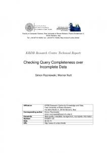
2 Motivation The work on automated checking of general safety criteria was partially motivated by our experience gathered during the design of Clt4iT, a safety-critical, multi-platform, embedded real-time system: a fire-alarm controller which is a part of a complex fire/ gas/ security alarm system. The Clt4iT system consists of a central unit and a set of data units that collect data from the detectors (smoke, fire, gas, etc.). Every unit can handle alarms independently, and has its own user interface. Since the amount of data originating in the units is large (detector information, alarms, logs etc.) and the communication bandwidth is low, only the recently changed data should be read into the central unit. The task of the central software is to keep record of the aging of data, poll the units, read the changed data or unconditionally refresh the aged ones. All units are monitored in this way; the units that are currently displayed on the screen are called active ones. Fig. 1 presents one of the statechart diagrams of the central unit software. Its responsibility is to handle the data aging for a given group of data. For each group, there is a time limit defined for data being “old” and “very old”, in the case of active operation, non-active operation, “changed” or “unchanged” data. The above-presented statechart defines the behavior of a “Model”-type class, which belongs to the internal data model of the system. In this type of class, there must be a distinguished state "Unknown" (which is the initial state, and represents that the internal data model is not up-to-date) and time-out transitions from each state to this "Unknown" state. The original version of the alarm system (which had to be replaced due to the change of the requirements) was developed on the basis of a verbal specification, without the use of UML. The design and implementation required more than half a year. Despite of the careful testing, residual software faults caused regular crashes of the system. The reasons of these failures were not found. The development of the new version started by a systematic modeling using UML. As a modeling tool, Rational Rose was used which supports XMI model export [9]. In this case the design and implementation required 4 months. Our goal was to develop automated tools for the checking of the dynamic UML diagrams of the design to highlight specification flaws early in the design process.
Fig. 1. One of the statecharts of the central unit of the Clt4iT system
3 General Safety Criteria N. G. Leveson and her colleagues have collected 47 safety criteria for the specification of software systems [3] and also elaborated checker methods for some of the criteria applied to the statechart-based languages RSML and SpecTRM [5, 6, 7]. The criteria are general and can be applied to all systems independently of the application area. In fact, they form a requirement safety checklist. These criteria can be grouped into several categories as follows: state space completeness, input variable completeness, robustness, non-determinism, time- and value limits, outputs, trigger events, transitions and constraints. The most important groups of these criteria target the completeness and consistency of the specification. Our main goal was to apply and check these existing criteria on UML statechart specifications. (The checking of a full UML model including object-oriented features like inheritance requires developing new criteria, which is out of the scope of this paper.) Accordingly, we had to formalize and adapt the criteria to UML statecharts and elaborate tools for automated analysis. Formalization and adaptation is a crucial task since the criteria are given in natural language thus they cannot be checked directly. Moreover, some criteria must be decomposed into a set of rules in order to be able to interpret them on the model elements of UML.
In a previous paper [13] we formalized the criteria in terms of the UML model elements and presented an approach to check some selected criteria by applying Prolog rules and by manipulation of the UML model repository. Now our analysis covers the full spectrum of the criteria excluding the ones related to timing and suggests efficient and elegant methods to check those of them that are amenable to automated checking.
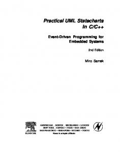
4 Overview of Checking Methods The analysis of the criteria proved that more than three-quarters of the criteria can be checked automatically (Fig. 2). Moreover, almost two-thirds of them are static criteria Necessary
Model transformation 28%
Possible
Complete
25
Manual check 15%
20 20
Other 8%
15
12
11
9
10 3
5
8
7 4
5
7
5
0
Reduced form 49%
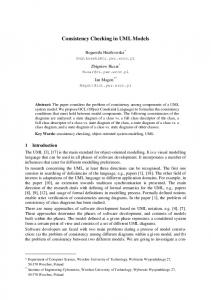
Fig. 2. The methods of checking
G O ra C ph L -tr an sf or m at io n Sp ec ia lp ro gr R ea am ch ab ilit y an al ys is
0
Fig. 3. The static methods
that do not require reachability-related analysis. The criteria that cannot be checked automatically refer mainly to assumptions related to the environment of the system to be checked e.g. environmental capacity, load assumptions, stability of the control loop. They are included in a checklist for manual examination. In the following, we examine four potential methods for automated checking of the criteria: (1) formalizing rules as expressions of the Object Constraint Language, (OCL [1]) as part of UML, (2) examining the satisfaction of the criteria by graph transformation, (3) executing a specialized checker program and (4) performing reachability analysis. Of course, some criteria can be checked in more than one way; in this case the most efficient one has to be selected. In Fig. 3, three numbers are assigned to each method. The first one gives the number of criteria that can be checked solely by that method. The second one shows how many criteria can be checked theoretically by that method. Finally, the third number shows how many criteria can be completely proven by that method. In the following, we give an overview of these methods and the typical criteria that can be checked. A more detailed analysis is found in the Appendix and in [16].
4.1 Completeness and Consistency Rules in OCL The most natural way to express criteria in UML is the application of the Object Constraint Language (OCL), since it is the language that was developed to specify the well-formedness rules of UML. These rules were given by a set of structural constraints interpreted on the metamodel elements of UML [1]. In our case, some of the criteria can be formalized in a similar way, by assigning constraints to metamodel elements. Let us present an example. One of the safety rules requires that all states must have incoming transitions (including the initial transition). Considering only simple states (that have no sub-states), this rule refers to the UML metamodel element SimpleState, and results in the following formalization: self->forAll(s:SimpleState | s.incoming->size > 0)
Note that OCL expressions are also well usable to formalize application-specific constraints, e.g. pre- or post conditions. Constraints interpreted on the UML metamodel can be enforced by a CASE tool that supports the modification of the metamodel. On the other hand, constraints interpreted over the model elements require a common OCL interpreter. In both cases, the checking requires an unfolded statechart model in which the hierarchy and concurrency are resolved, since OCL is not capable of browsing the state hierarchy. 4.2 Graph Transformation Techniques UML statecharts can be considered as a graph language [11]. Accordingly, graph transformation rules can be defined to modify or transform the statechart models [14]. These transformation rules can be utilized in two ways: − The model can be transformed into a form that is more suitable for checking. E.g. a hierarchic model can be flattened to check OCL expressions. − Systematically removing the complete and consistent parts of the model eventually results in the current specification flaws. Let us consider the following criterion: For all states, there must be a time-out transition defined. It can be checked in the following way: 1. Converting the state hierarchy into a flat model (for details see Section 5 and [11]). The approach is illustrated in Fig. 4. a) UnChanged NewData
New
OnTimer
b) OnTimer VeryOld
Old
NewData NewData OnTimer OnTimer New
VeryOld NewData OnTimer
OnTimer
Fig. 4. Example for resolving the state hierarchy
Old
2. Looking for the following situation: There is a SimpleState in the graph AND there is NO Transition connected to this with the stereotype “TimeOut” OR with an action “OnTimer”. In general, the graph transformation rules are defined by giving a left side (condition) and a right side (result). The system tries to match the left side on the source model. If it matches then transforms this part of the model into the right side of the rule. The transformation is ready, when the rule does not match any more. In our case, it is not practical to modify the source model. Instead of this, a second model is built, that will contain the result of the transformation steps. Accordingly, the left and right sides of the rule are duplicated, describing the condition and the result including the patterns both in the source and in the target model (of course, the source will not change) [14]. Currently the graph transformations are implemented in Prolog. The UML CASE tool saves the model in standard XMI format (using XML as model description language [15]). This common representation is parsed and loaded into memory as a set of predicates. The rules are executed and the resulting model is saved again in XMI format, which can be loaded into the CASE tool to highlight the specification flaws. 4.3 Checking by Specialized Programs Some criteria cannot be checked by graph transformation and/or the assignment of OCL constraints. We mention here one criterion: for each state and each trigger event, the guard conditions must be mutually disjoint. The checking of this rule requires the interpretation of the guard expressions, which cannot be done by a generalpurpose OCL interpreter (that targets structural constraints) or by graph transformation (as the values of the guards dynamically modify the model structure). To verify the guard conditions, we restrict the use of guards similarly to RSML [5]. We require expressions built from atomic propositions (that are true or false) connected by Boolean operators OR, AND or NOT. Accordingly, we can assemble a disjunctive normal form of the propositions and a truth table of the terms. Using this form, the guard conditions can be converted to events and transitions. After a standard optimization, which can find and eliminate uniform cases [4], the checker removes all original transitions starting from the given state and triggered by a)
c)
b) Unknown On Changed/
Unknown Unknown
NewData/0
On Changed/ NewData/1
NewData
[!IsChanged] IsChanged
NewData/0
NewData/1
IsChanged=0
IsChanged=1 NewData
Fig. 5. Example with two guard conditions
the given event. Then for each term of the normal form (combination of guard conditions), it generates a new virtual event and a transition triggered by that virtual event. In this way, guarded transitions will be resolved by virtual events, and the mutual exclusiveness checking is traced back to the checking of the trigger events. Fig. 5 (a) shows one state from our example. According to the guard expressions "IsChanged" and "!IsChanged", here two virtual events are generated from the original event "NewData" (Fig. 5 (b)). The original transition is replaced with the ones triggered by the virtual events (Fig. 5 (c)). 4.4 Reachability Analysis There are criteria that require reachability analysis. To formalize and check these criteria, temporal logic expressions and model checking can be used. Typical reachability problem is the checking of the existence of unreachable states and transitions that can never fire. The rule that prescribes that each output action must be reversible is a similar problem. Another important consistency criterion is related to the avoidance of nondeterminism. In UML statecharts, one source of nondeterminism is the simultaneous firing of transitions in concurrent regions of composite states. In this case the order of their actions is not defined. The suspicious state pairs can be found by static checking, i.e. looking for situations where transitions in concurrent regions are triggered by the same event, guards can be true at the same time and there are actions defined. However, the static checking cannot claim that these state pairs are reachable during the execution of the system. We use the model checker SPIN [10] as external tool to decide reachability problems. The UML statechart is transformed to Promela, input language of SPIN [8], and the reachability problem is formulated in linear temporal logic (LTL).
5 The Reduced Form of UML Statecharts During the elaboration of the checker methods and identification of the basic rules that are sufficient and necessary to check the criteria, we discovered that checking of several criteria could be traced back to the same set of basic steps. The common characteristic of these steps is that their execution results in a simplified, flattened model structure that is easier to check (both by OCL constraints and graph transformation). We call this model structure the reduced form of the statechart. The reduced form was utilized also during the formal proof of the correctness and completeness of the proposed checking methods. For a given criterion, it is proved first that the steps generating the reduced form preserve the properties to be checked. Then the proof of the later steps can be built on the relatively simple and formally tractable reduced form. Fig. 6 shows the UML metamodel of the reduced form of statecharts. It has several advantages. The special UML elements are removed or converted into the set of "standard" ones consisting of simple states, transitions, events and actions. The hierarchy is resolved and the model is fully static, no guard conditions are in the model. The reduced form is generated by a series of graph transformation steps as follows:
Fig. 6. UML metamodel of the Reduced form of statecharts
1. Multiple statechart diagrams in the UML model are merged into a single diagram. 2. Associations are inserted among states and events (the checker must verify all states and all possible events on that state, i.e. the Cartesian product of the set of SimpleStates and Events). 3. Temporary states (SimpleStates that have completion transitions, i.e. an output transition without a trigger event defined) are eliminated, since they are not part of any stable state configuration. The completion transitions are converted into a set of regular transitions, where there is exactly one transition for each possible event - this method also saves the information of the guard conditions. 4. Associations are inserted between each pair of concurrent states. Since the state hierarchy will be converted into a flat model, the information on the concurrency of states should be kept. 5. The state hierarchy is converted into a flat model. Every SimpleState inherits the outgoing transitions of its parent states and the initial states inherit the incoming transitions of their parent states. The associations between the SimpleStates and their parents are preserved. 6. Entry (exit) actions are moved to the incoming (outgoing) transitions. Entry (exit) actions are last (first) ones in the sequence of actions executed by the incoming (outgoing) transitions [12]. 7. Internal events are converted into self-loop transitions. Since the entry and exit actions were already removed in the previous step, this step does not violate the semantic rules of UML. 8. Pseudo-states (e.g. initial and final states) and composite transitions are converted into normal states and transitions. Fork transitions are marked, otherwise the resulting transitions starting from the same state and triggered by the same event would result in inconsistency. In the case of join and Sync transitions, the source states are assigned a self-loop transition guarded with an "in_state" condition. 9. Guard conditions are converted into events (see Section 4.3). Let us present an example how the reduced form is used. Since there are only simple states and transitions in the model of reduced form, the criterion of the completeness of state transitions can be formalized in OCL as follows:
self -> forAll(s:State | s.myevent -> forAll(e:Event | s.outgoing -> select(t:Transition | t.trigger = e) -> size > 0))
Almost all criteria can be checked on the reduced form. In some cases, however, it turns to be more practical to use the original model. E.g. the Promela code used during reachability analysis is generated on the basis of the original statechart.
6 Conclusion This paper presented methods and tools for the checking of UML statechart specifications of embedded controllers. The existing criteria given in [3] were adapted to UML statecharts and efficient methods were proposed for the automated checking. The developed methods were successfully applied in the case of the Clt4iT system. The general safety criteria were checked for all statechart diagrams. The automatic checking of a statechart using the graph transformation framework required about 30 seconds in average. Since there was only limited concurrency in the system, the state space explosion problem was practically avoided. By the automated checking, (besides some typing errors) typically incompleteness due to malformed guard conditions and missing transitions were detected in the early design phase. The validation testing detected additionally some non-suitable settings related to timing (that could not be checked in the design phase). The problems that occurred in the previous system did not appear in the new version.
References 1 2
Object Management Group: Unified Modeling Language Specification v 1.3. (1999). B. P. Douglass: Real-Time UML - Developing Efficient Objects for Embedded Systems. Addison-Wesley (1998) 3 N. G. Leveson: Safeware: System Safety and Computers. Addison-Wesley (1995) 4 N. G. Leveson, M. P. E. Heimdahl, H. Hildreth, and J. D. Reese: Requirements Specification for Process-Control Systems. IEEE Trans. on SE, pp. 684-706 (1994) 5 M. P. E. Heimdahl and N. G. Leveson: Completeness and Consistency Checking of Software Requirements. IEEE Trans, on Software Engineering, Vol. 22. No. 6 (1996) 6 N. G. Leveson, J. D. Reese and M. Heimdahl: SpecTRM: A CAD System for Digital Automation. Digital Avionics System Conference, Seattle (1998) 7 N. G. Leveson, M. P. E. Heimdahl, and J. D. Reese: Designing Specification Languages for Process Control Systems. Lessons Learned and Steps to the Future. 8 D. Latella, I. Majzik, M. Massink: Automatic Verification of a Behavioral Subset of UML Statechart Diagrams Using the SPIN Model-checker. Formal Aspects of Computing, Vol. 11 No. 6 pp 637-664, Springer Verlag, (1999) 9 Rational Corporation. Rational Rose 2000. http://www.rational.com/ 10 G. Holzmann: The Model Checker SPIN. IEEE Transactions on Software Engineering, Vol. 23, pp 279-295 (1997) 11 M. Gogolla, F. Parisi Presicce: State Diagrams in UML: A Formal Semantics using Graph Transformation. Proc. ICSE'98 Workshop on Precise Semantics of Modeling Techniques (PSMT'98), pp 55-72. (1998)
12 M. Gogolla: Graph Transformation on the UML Metamodel, Workshop on Graph Transformation and Visual Modeling Techniques, ICALP’2000, Geneva, Switzerland, 2000 13 Zs. Pap, I. Majzik, A. Pataricza and A. Szegi: Completeness and Consistency Analysis of UML Statechart Specifications. Accepted to DDECS-2001, Győr, Hungary (2001) 14 D. Varró, G. Varró, and A. Pataricza: Automatic Graph Transformation in System Verification. In Proc. DDECS-2000, pp 34, 2000. 15 Object Management Group. XML Metadata Interchange. (1998). 16 Zs. Pap: Checking Safety Criteria in UML Statecharts (In Hungarian). Technical Report No. 2/2001 of the DMIS, Budapest University of Technology and Economics, 2001.
Appendix Table 1 presents the groups of general safety criteria (without the timing related ones) and the methods required to check them. (We introduced groups here because the methods of checking the criteria cannot be clearly separated, and some criteria must be decomposed into several rules.) In the Table, "Yes" means that the method is applicable and necessary, "No" means that the method is not applicable. "-" means that the method is applicable but not optimal to check the given group of criteria. Group of criteria
Static Methods Graph Transformation
Special Program
Reduced Form
Reachability
Conditional
Manual
OCL The system should start in a safe state The internal model must be valid All variables must be initialized The specification must be complete The specification must be deterministic There must be timeout transitions defined No path to critical states should be included There must be behavior specified in the case of overloading All states must be reachable All valid output values must be generated Paths between safe and unsafe states (soft and hard failure modes) Repeatable actions in live control loops Limits of data transfer rate must be specified The time in critical states must be minimized The output actions must be reversible All input information must be used Control loops must be live and checked All input values must be checked The overloading parameters must be defined
Others
Yes Yes Yes Yes Yes Yes
Yes Yes -
Yes Yes Yes Yes Yes Yes No Pre
Yes Yes -
Yes Yes
Yes
Yes Yes Yes Yes No Yes
Yes Yes
Yes Yes Yes Yes Yes -
Yes -
No No No No No No Yes No
Yes Yes
No Yes Yes Yes
Yes Yes Yes Yes Yes Yes Yes
No No Yes No No No Yes No
No Yes No Yes No No Yes Yes
Yes Yes -
Yes Yes Yes Yes Yes
Table 1. Groups of criteria (without the timing related ones) and the checker methods