Transformation of SBVR Business Design to UML Models Amit Raj
Unisys Global Services India 135/1, Residency Road Bangalore - 560 025
[email protected]
T. V. Prabhakar
Deptt. of Computer Science IIT - Kanpur Kanpur - 208016
[email protected]
ABSTRACT
∗
Stan Hendryx
Hendryx & Associates Sunnyvale, California USA
[email protected]
Model (PIM) and Platform Specific Model (PSM) etc. The development of a business model is the stage where a Business Analyst (BA) designs and puts the constraints on the system. The OMG’s SBVR is an approach which allows to create the business design in terms of business vocabulary and rules in natural language format. SBVR was originally developed to share the business semantics between different communities. Transferring the business semantics from business people to IT people introduce some inconsistencies. The contribution of this paper is to bridge the gap between business people and IT people in order to minimize the loss of semantics. The paper shows how to create the business design on SBVR and also shows how to transform them to PIMs.
This paper presents a methodology for transforming business designs written in OMG’s standard Semantics of Business Vocabulary and Rules (SBVR) framework, into a set of UML models. It involves the transformation of business vocabulary and rules written in SBVR’s ”Structured English” into a set of UML diagrams, which includes Activity Diagram(AD), Sequence Diagram(SD), and Class Diagram(CD). This transformation works by detecting the distinction between rules which will participate in the construction of Activity Diagram and rules which do not. These rules are imperative in nature. The work in the paper also includes the detection of activities embedded implicitly in those rules and establishment of sequence between those activities. These activities incur some action. We also detect their owner and refer to them as the doer of the action. This plays a very important role in the development of Class Diagrams.
Computation Independent Model (CIM) SBVR based Business Model
Other Business Model
Categories and Subject Descriptors
Platform Independent Model (PIM)
UML Model
D.2.2 [Object-oriented design methods]: Flow charts; D.2.1 [Methodologies]: [Business Requirements and their models, Flow Charts - UML Activity Diagram. ]
BPMN Model
Platform Specific Model (PSM)
General Terms
Dot Net Application
J2EE Application
Design, Algorithms, Languages.
Keywords
Real World Application
Model Driven Architecture, SBVR, Business Design, Production Rule Representation, Business Rules, UML.
1.
INTRODUCTION
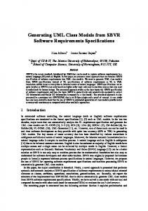
Figure 1: OMG MDA’s Modeling Layers
Development of a system involves a set of stages like the development of a business model, a Platform Independent
Main challenge in transforming the Business Model to PIM as shown in Figure 1, is the detection of automatable business rules and their automation. ”Automating” a rule means to enforce the rule through automation. In general, an enforcement policy needs to be specified for each rule and putting an obligation on the system or process as to exactly how, when, and where the system or process will enforce the rule. That is, there should be a rule or a set of rules for each automatable rule about how each of them will be enforced by the system and in this paper we are trying to develop that set of rules. This is often non-trivial, as there are often several options available, and it is a system design choice which one to use. Additionally, the enforcement may be complex,
∗The author is a part of SBVR and MDA specifications.
Permission to make digital or hard copies of all or part of this work for personal or classroom use is granted without fee provided that copies are not made or distributed for profit or commercial advantage and that copies bear this notice and the full citation on the first page. To copy otherwise, to republish, to post on servers or to redistribute to lists, requires prior specific permission and/or a fee. ISEC’08, February 19-22, 2008, Hyderabad, India. Copyright 2008 ACM 978-1-59593-917-3/08/0002 ...$5.00.
29
• Terms: These are the noun or group of words which can be collectively used for the designation of a business entity. For example:
involving many steps and coordinated activity to enforce the rule. This information is generally not in the automatable rule itself, but involves other considerations too. The contribution of this paper is to analyse all those requirements and presenting a methodology which allows business people to convert their business designs into UML Activity Diagram, Sequence Diagram and Class Diagram. Eriksson et., al., in his book [13] has shown the business modeling with UML. The paper is organized as follows: the next section present the definition of SBVR and shows the structure to present the meaning of a rule. The paper then presents a methodology to automatically transform the business vocabulary and rules written in SBVR into UML AD, SD and CD. The examples used to demonstrate the methodology has been taken from [21] which shows the interaction between an atm and a user. Then it presents a discussion which includes the utility and limitations of the approach followed by related and future work and finally it end up with a conclusion.
2.
”bank” or ”investment bank” • Name: These are the words which are used to represent the instance of a particular term. ”SBI” which is an instance of bank. • Fact Type: These are the sentences which represent the relationship between terms. We are using the template term-verb-term to establish the relation between two terms, as it is very obvious that a mutual relationship between 3 entities can be easily break down to maximum of 3 binary relations. For example, the fact type ”customer owns account is member” states that a customer is related with account and account is related with member and a person who owns an account will be a member. This relationship can be breakdown to two relations as described by the two fact type like ”customer owns account” and ”customer is member”.
SBVR
SBVR is an abbreviated form of ”Semantics of Business Vocabulary and Rules” which has been accepted by OMG in 2005. OMG’s Model Driven Architecture (MDA) [5] is a multi layered approach to implement a real world application. SBVR is completely compatible with MDA and behaves as a Computational Independent Model. Compatibility with MDA increases its adoption by several business organizations. SBVR is an approach to allow the business analysts or any business person, who is interested in writing the business rules, to express the business artifacts in natural language format. A business person can write them in his own language and can create a semantic model for it. This semantics model could be same for different business designs in different languages because semantic metamodel of SBVR is totally independent of representation [10]. The basic mantra of SBVR is ”Rules are built of fact types and fact types are built of terms” which is clearly described in Figure 2 with example.
2.2
SBVR Business Rules and Their Parsing
These are the sentences under business jurisdiction which guide the structure and behavior of an organization. The rules guiding the structure are known as Structural Rules and the rules guiding behavior are known as Operative Rules. SBVR allows 4 types of expressions as given in [10], to create the business vocabulary and rules. To parse the business model given in SBVR, we have to just identify the 4 types of expressions i.e. term, Name, Verbs, Keywords explained in [10].
2.3
Logical Formulation
Every rule presents some semantics of a business artifact. SBVR provides a structure to formulate that semantic which is known as logical formulation. It is an abstract and language independent syntax to represent the meaning of a rule as described in Figure 3. Some of the terminology used in Figure 3 is not described in the paper but properly explained in [10].
Figure 2: SBVR Schema Model SBVR has its own set of keywords and terminology to write the business vocabulary and rules. Following is a little introduction with its terminology given in [10].
2.1
SBVR Business Vocabulary
SBVR Business Vocabulary is the collection of business entities, their instances and relationships between them, which can be used by any organization in their writing and talking during the course of their business.
Figure 3: Logical Formulation of a SBVR Rule SBVR Specification [10] also provides a Meta Object Facility(MOF) [4] representation of Logical Formulations.
30
3.
SBVR TO UML ACTIVITY DIAGRAM
”automatable” which will compensate for the information required, as given in Figure 5. The result of adding the level ”automatable” will result in detection of automatable and non-automatable rules at the time of writing rules.
Not all the rules will participate in the construction of AD, as it shows the execution behavior not the structure. Ignoring the structural rules, we will consider only operative rules. A subset of those operative rules will help in generating the AD and we will name them as the automatable rules. Logical formulation of automatable rules will be used to create the activity diagram. Automatable rules are generally in the form of if-then or Event-Condition-Action(ECA) format [11]. Logical formulation of these rules is defined as implications, which will help us to find out the activities and their precondition and sequence between those activities. A detailed discussion of this methodology is given in following sections.
3.1
It is obligatory that each atm requests exactly one password if the user inserts card. Guidance Type : Description :
operative business rule Each atm will request the password of card if the user has inserted the card in atm. Enforcement level: automatable Supporting fact type: atm requests password user inserts card
Figure 5: Rule Signature for automatable rule
Categorization of Rules
If the user sets enforcement level as automatable, it means that this rule should be completely handled by the IT system and participate in generating the activity diagram.
The business rules can be categorized as structural rules and operative rules. As described in the above section, structural rules will only participate in the structure of the business organization but would not guide the business flow. Operative rules are the rules which will guide the business flow, so a distinction between the operative and structural rules is required, which has been done in the SBVR Specification [10]. As our intension is to draw the execution behavior of a system on a UML Activity diagram, we must consider only operative rules ignoring the structural rules. But not all the operative rules will participate in activity diagram, so we again categorize them according to their Information Technology(IT) support as given in [18].
3.2
Logical formulation of Automatable Rules
Automatable rules generally shows the execution of activities and most of the activities should be guarded by some pre-conditions. This is why most of the automatable rules exist in if-then construct in SBVR, but they may exist in some more constructs. For this paper, we are mainly handling if-then construct. In SBVR, the logical formulation of if-then rules is given as ”Implication”. An if-then rule relates the activity and its preconditions with the consequent and antecedent of the implications, respectively, as shown in the Figure 6. A visual presentation of this concept is given as follows: Rule:
• IT support = automated: These are the rules which should be completely handled by IT system without any intervention of human user. We will refer these rules as automatable rules for rest of the discussion.
it is obligatory that each atm request exactly one password if a user inserts card
• IT support = supported: These are the rules which are supported by IT system and expect some human interventions. The rules which are completely supported by IT will be named as automatable rules for rest of the paper, and these rules will be used to create the AD. Business rule writer is the only person who knows which rules are automatable and not. We will allow him to express this knowledge with rules at the time of writing the rules. For example, a typical SBVR business rule signature is given in Figure 4 in which it is shown that a rule includes some attributes whose detailed discussion is given in [10]
Implication
Antecedent
Atomic Formulation
Fact Type
user inserts card
Consequent
Atomic Formulation
Fact Type
atm requests password
It is obligatory that each atm requests exactly one password if the user inserts card.
Figure 6: Logical formulation of if-then rules
Guidance Type : Description :
operative business rule Each atm will request the password of card if the user has inserted the card in atm. Enforcement level: strict Supporting fact type: atm requests password user inserts card
To deduce the ”if p then q else r”, we will decompose the else part again in ”if-then” construct. For example if p then q else r
Figure 4: SBVR Rule Signature can be decomposed as The ’enforcement level’ tells how to enforce the rule. A details list of different level of enforcement is given in [10] based on Business Motivation Model [1], but there is no level which would inform us about whether a rule is automatable or not. So, we have added another level named
if p then q and if !p then r
31
3.3
Fact Types: Activities in an Activity diagram
checked, if the condition holds true, then the corresponding action occurs and brings another activity into existence. It is not necessary that a transition must have trigger. Transitions without the trigger is known as trigger less transitions. A typical SBVR operative rule may be written as:
As we have already discussed that a fact type can be represented as term-verb-term. A verb can be of two types, one which imply some action (transitive verbs) and other which doesn’t imply any action (intransitive verbs). The statements involving the transitive verbs will represent some action. For example, the fact type ”user inserts card” is a statement which include a transitive verb ”inserts” and shows an action ”insertion of card into atm”. These types of fact types can be assumed as the activities. The fact types having intransitive verb e.g ’has’ or ’is of’ will not be considered as the activities because they shows the structural nature not the imperative nature. For example ”card has pin” shows that pin is an attribute of card. Naming of activities can be done in the following two ways.
So, the mapping from these type of SBVR rules to UML AD will create the trigger less transitions. The propositional expression 2 will help to find out the guard condition and propositional expression 1 will help to find out the action.
• Direct: Use the fact type name directly as the activity name.
• Guard Condition: Assume an operative business rule like given below. The propositional expression 2 in
upon event, if , then . But we are using the following format of operative business rules in SBVR [if ]
• Objectification: Use the objectification of fact types. SBVR has a provision for giving instances of fact types a type name; it is called ”objectification” [10]. For example, an occurrence of the fact type ”user inserts card” might be objectified as ”card insertion”. An objectification allows us to predicate things about a fact type, like how, when and where they happened, etc. Each activity in a UML AD may corresponds to an objectification. The corresponding transformation turns the fact type into a command to bring such an action into existence. Use of the infinitival form of the verb phrase of the underlying fact type for an activity name might be preferred, to reflect the imperative nature of the activity: ”insert card,” the successful outcome of which is an ”card insertion”.
it is obligatory that each atm request exactly one password if a user inserts card
if clause refers to the fact type ’user inserts card’. Depending upon the fact type, we are creating a boolean variable like ’inserts card’. And the guard condition will become ’insert card == true’ as shown in Table 1. Fact Type user inserts card atm request password
• Action: These are the actions which should be invoked during the transition from one activity to another. For example in the above rule, if a user inserts a card in the atm, then the atm will do an action ”request password”. What we are doing is taking the propositional expression 1 and find out the corresponding fact type. Merging of verb and last term of the fact type will create the name of the action like ”request password()” as shown in Table 2.
SBVR to UML Activity Diagram Mapping Rules
This section mainly deals with the mapping of SBVR components to UML Activity diagram components.
3.4.1
Fact Type user inserts card atm request password
Initial Node
3.4.4
Activity Node
ForkNode/JoinNode
• ForkNode: This is a pseudo-state where one transition is coming and multiple parallel transitions are going out of it. A SBVR rule like ”’it is obligatory that each atm print exactly one receipt and each atm eject the card if bank return badAccountmessage”’ represent the enforcement of two activities ”’atm print receipt”’ and ”’atm eject card”’ on the delivery of bad account message from the bank. This situation will generate the fork state. There will be an incoming transition
As we have already discussed in section 3.3, the fact types having transitive verbs will be assumed as the activity node.
3.4.3
Corresponding Action inserts card() request password()
Table 2: Fact types(activities) and corresponding Actions
This is the start state of the activity diagram. It doesn’t play a very important role but significantly shows the starting point of a scenario. We have given it a default name ”start”.
3.4.2
Corresponding condition inserts card = true request password = true
Table 1: Fact types(activities) and corresponding pre-condition
The fact types associated with the automatable rules will be used to form an ordered set of commands. It is a very sensitive and non-trivial process as it must consider both linguistic and logic especially the temporal aspects all of which may not be specified directly in the set of declarative rules. This transformation must be logically consistent with the conceptual schema of SBVR.
3.4
Corresponding Boolean Variable inserts card request password
Activity Edge
An activity edge is a set of event, guard conditions and actions which allows the transition from one activity node to another activity node. An event is the trigger of the transition. Upon triggering the transition, the condition is
32
having the guard condition ”’return badAccountmessage == true”’ and two outgoing parallel transitions pointing toward activities ”’atm print receipt”’ and ”’atm eject card”’.
one such rule, then there will be two transitions from start state which is against the UML AD Semantics. It is only possible if those two activities occur in parallel, which will be modeled as fork in AD. The fact type corresponding to the automatable rule having no if clause, will be the first activity. Create a boolean variable as shown in the section 3.5, assign it as true and put into the RSE-DB. The detection of further activities will be done with the help of ”implications” given in SBVR Metamodel.
• JoinNode: This is another pseudo-state where multiple parallel transitions are coming and only one transition is outgoing. The generation of this state will be same as the above except there will be multiple guard conditions and only one outgoing transition.
3.4.5
ActivityGroup
After deducing the logical formulations, we will look up at all the ’obligation claims’ [10] that are ’implications’ to find out the relation between the fact types of ’if’ construct (antecedent of the implication) and those of ’then’ construct (consequent) in an if-then construct. To find out the next activity, check the RSE-DB to know whether the guard condition corresponding to the fact type in antecedent is true or not. If the guard condition holds, find out the fact type corresponding to consequent of the implication and make it as the next activity and also create a corresponding boolean variable with assigning ”true” value and put it into the database of RSE. Also, create a transition from previous activity to the current activity as explained in section 3.4.3. If the guard condition doesn’t holds, then search for the next implication until all the implications get visited. The absence of such an implication will result in the end state.
The ActivityGroup in UML activity diagrams are generally known as swimlanes which basically represents who is doing the activity. The entity doing an activity will be referred as the giver of the activity. As we have already discussed that the representation of fact type(activity) can be of two type, active form and passive form. In a sentence having an active, transitive verb, the giver of the action of the verb is the subject of the sentence. In English, the ”giver” corresponds to the object filling the role of the first placeholder in the fact type form, e.g. ”customer” in ”customer places order.” If the fact type form is passive, e.g. ”order is placed by customer,” it is the reverse. These means the same thing. They are synonymous forms. Facts of either of these forms would be logically equivalent.
3.4.6
Activity Final Node
This is the point in an activity diagram where all the activities get end up. We are creating a default end state with the default name ”End”.
3.5
Start
Create Vocabulary and Rules
Rule Sequencing Engine
Parse and Create logical formulation(LF)
Rule Sequencing Engine(RSE) is an engine used to establish the order between activities. The engine consist of a data structure(RSE-DB) used to contain the guard conditions which have been occurred as true and a decision unit to decide the next activity. For example, if we encounter a rule like below then the fact type corresponding to if clause
Find automatable rule with no if clause
Get the fact type from its LF
Create a start state
Create transition with var == true as guard and activity’s function as action Look up at an implication
it is obligatory that each atm request exactly one password if a user inserts card
Non visited implication > 0 Make the fact type as first activity
is ”user inserts card” and corresponding guard condition will become inserts card == true. The RSE search its RSE-DB for this condition to be true, if the condition exist and holds true, then the fact type ’atm request password’ corresponding to then clause will be the next activity. After getting the next activity, a boolean variable ’request password’ is created and get set to true and inserted into the database. This concept is motivated from OMG’s Production Rule Representation (PRR) [9] and RETE Algorithm [14].
3.6
Create boolean variable, assign true and put into RSE database(RSE-DB)
Get fact type of antecedent Variable == false and find corresponding boolean variable as true in RSE-DB Non visited implication = 0 Variable == true
Create transition from current activity to end state
Get fact type of consequent and make as next activity and mark implication visited
Figure 7: Flow Chart of SBVR To UML Activity Diagram Transformation The flow chart showed in Figure 7 present a general algorithm to find out the activity diagrams. The special situation like an activity doesn’t have any outgoing transition, fork and join; multiple incoming transitions to the end state are not shown in the flow chart. They can be directly hard coded on top of the basic algorithm shown in above flow chart.
Algorithm
The vocabulary and rules are parsed and instantiate the SBVR Meta- Model given in [10]. Chapter 9 in [10] deduces the logical formulation of a SBVR business rule. The logical formulation of an automatable operative business rules will be of our interest at the moment, as we are modeling the activity diagram. Since we are generating the UML AD based on the business artifacts given only in if-then rules, there must be exactly one automatable rule which would not have any if clause. This is because the absence of pre-condition will allow the activity to occur initially. If there is more than
3.7
Example
Following are some snapshot of case study performed on the tool developed by us. The vocabulary and rules are generated for an atm machine and showing the interaction
33
4.1
with user. Figure8 is a snapshot of vocabulary showing the terms and fact types for atm and user interaction.
Mapping SBVR to UML Sequence Diagram components
The SDs requires the messages having proper sequence between them along with their source and destination object information. The AD contains the activities with proper sequence but don’t give any information about the objects. In the following sections, we will see how the activities and their sequence in AD can be used to create SDs.
4.1.1
Message
The messages in a SD are responsible for the occurrence of events and actions in the sequence diagram. Due to its logical similarity with the activities of AD, they can be given the same name as of the activities. For example, the activity ”atm ejects card” in an AD can be a message in a SD. The messages toward the life line of an object show the event on the object while the messages away from an object are considered as the actions of that object.
4.1.2
Figure 8: A sample sbvr business vocabulary. Figure 9 is a snapshot of the rules developed on top of the vocabulary given in Figure 8. We are not able to show all the rules due to space problem but showing some rules which can clear the methodology expressed above. The attributes of the rules shows whether it is operative or not and also automatable.
4.1.3
Destination object of a message
The destination object of a message is one at which a message get end up. That object will be the active object in the system means the execution control will retain with this object only. Every message has its own source and destination. For example take two messages as shown below:
Figure 9: Sample sbvr business rules. The rules ”it is obligatory that each atm display exactly one main-screen” in Figure 9 doesn’t have any precondition. So, the execution flow will start from this rule. This rule is associated with an atomic formulation which is based on the fact type ”atm display main-screen”. We will create an initial activity and name it same as the fact type ”atm display main-screen”. Similarly, the whole AD will get generate. A snapshot of the generated AD is given in Figure 10.
4.
Source Object of a message
The source object of a message will be the ’doer’ of activity having same name as of that message. The semantics of ’doer’ is same as the ’subject’ in an English sentence having an active verb. The subject is the noun who performs the action of the verb. In SBVR’s structured English, a sentence having an active, transitive verb, the ’doer’ of the action of the verb is the object filling the role of the first placeholder [10] in the fact type form e.g ”user” in ”user inserts card”. If the fact type form is passive e.g ”card is inserted by user”, then the ’doer’, would be the object filling the role of last placeholder. The above two sentences have the same meaning and must be presented as the synonym of each other by BA during the development of Vocabulary. However, it is preferable to use the active form wherever possible. The above two fact type forms would have the same logical formulation or logically equivalent.
• source1
- message1
- destination1
• source2
- message2
- destination2
Assume message2 is next to message1 in the sequence. After the occurrence of message1 , destination1 will be the active object and for the occurrence of message2 , source2 should be the current active object. This implies that destination1 should be same as source2 as shown below:
SBVR TO UML SEQUENCE DIAGRAM
The scenarios within an environment can be represented as a sequence diagram which is described in [21]. [21] says that a sequence diagram can be represented as the set of messages with the information of their source and destination object in a sequential manner which is represented below:
source1 - message1 - destination1 = source2 - message2
It implies that the destination of a message will be the source of the next message in the sequence.
4.1.4
src1 - msg1 - dest1 ; src2 - msg2 - dest2 .... srcn - msgn - destn ;
To draw the sequence diagrams for the scenarios described by SBVR Rules, we will use the AD generated in the last section.
State Invariant
An object in its life time, passes through several states. These states are the different configuration of variables of the object. For example, the object ”atm” has the variables ’card’ and ’password’ of type string and ”card=null and password=null” represents a state of ”atm”. The state change of
34
Figure 10: Sample Activity diagram from above sbvr vocabulary and rules. Start
the object occurs due to their action and events. For example, the action ”user inserts card” will change the value of card to ”card=c” and results in a new state(new configuration) of atm ”card=c and password=null”. The invariants to the state can be attached in many way like in plain english or Object Constraint Language(OCL) [6]. It depends upon the user and his requirements, how to attach them.
4.1.5
Create Vocabulary and Rules
Parse and Create logical formulation(LF)
Generate Activity Diagram
General Ordering Get initial activity
The General ordering in UML SD Metamodel [8] is a partial ordering between the two messages. So, we will look up only at the two activities in UML AD generated above and map their ordering to the general ordering of messages.
4.2
Create message of same name of current activity
Algorithm
Assign action of current activity as action of current message
The generation of UML SD involves the collaboration of both UML AD and SBVR Metamodel. The flow chart for this transformation is shown in Figure 11. The algorithm tries to find out the messages of the SD. According to [19], only activities of the AD can be transformed to messages of the SD. Hence, we will set all the activities of AD as the messages of SD. The first activity in AD will be mapped to the initial message of SD. And the action corresponding to this initial message will be the same as the action corresponding to that activity in AD. This action will become the send event of the destination message end. We will generate the general ordering of messages through the sequence between the activities in AD. The next thing is to find out source and destination life lines for a message. A detailed discussion of algorithm is given below. The name of a message would be the name of activities which in turn is the fact types, as discussed in section 4.1.1. In SBVR metamodel, each fact type has some roles which are situated at some placeholder. If the fact type(which is a message in SD) is in active form, the source life line of the message will be the term at first placeholder else it will be the term at last placeholder. To find out the destination life line, we will look up at the next message of current message in general ordering. The source of the next message will be the destination life line of current message as described
Create message of same name of current activity and set order
Get next activity in AD If AD is not traversed completely
Get fact type corresponding to current messge Active form
Get term at first placeholder
Set the term as destination
Passive form
Get term at last placeholder
Find source of next activity in AD Else
Set the term as source If no next activity
Set the term as destination
Figure 11: Flow Chart of SBVR To UML Sequence Diagram Transformation
in section 4.1.3. This whole process is repeated again from finding the next activity, creating a message and finding the source and destination lifelines for messages, until we will not traverse all the activities in AD and reach the end state from all the possible paths. There may be some consecutive activities in AD whose sources are same. For example the consecutive activities ”atm print receipt” and ”atm ejects card” have the same source ’atm’. In this case, the message corresponding to the activity ”atm print receipt” will be a self message. A self message is a
35
message whose source and destination are same. Due to this self message, the active object after the occurrence of this message will remain the same which is ’atm’. And next message ”atm eject card” will be sent from the object ’atm’. It may also happen that the activity next to current activity doesn’t exist in an AD, for instance, the activity immediate previous to the end state. This activity doesn’t have any next activity. In this case, we may have to compromise as there is no information for the next object. If we see the messages, they are transferring the control to the next destination object. And if there is no information about the next active object to take over the control, we have to keep the control to current object. Due to which, the destination life line for this message will be the same as source life line. This is a limitation of this approach and will be recovered in future work. In this approach, we are missing the detection of actors. As our intension is to map the SBVR Metamodel to UML SD metamodel not the UML SD syntax, this is not important at the moment as UML SD Metamodel doesn’t include any entity like actors.
5.
sentence is active else it will be the term at first placeholder. For example, in the binary fact type in active form ’atm has card-reader’, the class ’atm’ will have an attribute ’cardreader’ which is of type ’machine’. Ordinarily a unary fact type is transformed into a UML Boolean attribute. For example, in the unary fact type ’atm is open’, the class ’atm’ will have a boolean attribute ’is open’ as shown in Figure 13 .
atm Is_open : boolean
Figure 13: Class and its instance name • Generalization and Specialization: [10] says that ’concept1 specializes/generalizes concept2’ which means that a term can be specialized or generalized form of another concept.
SBVR TO UML CLASS DIAGRAM
The SBVR statements(business vocabulary and rules) are declarative in nature. These statements are used to declare the structural and operative behavior of the system. The structure of the system mainly involves the classes, attribute, functions and relationships between those classes. For example, ’atm’ is a class which is a SBVR term and ’atm has card-reader’ is a SBVR fact type which shows that the class ’atm’ has an attribute of type ’card-reader’.The business rules determine the correct value of the properties that an object will have and methods of deriving the information needed by the class. Appendix H in SBVR Specification [10] gives a mapping from the SBVR Vocabulary and Rules to the CD but it is not sufficient as it does not give any information about the functions of business objects. The contribution of this paper is to find out the functions of the classes, association between them and cardinalities for association ends. Some of the important rules of the mapping are described here. Mapping Rules in SBVR Specification:
The example above shows that the term ”branch manager” is a specialized role of ’manager’. So, the class corresponding to the term ’branch manager’ will be a subclass of the class corresponding to the term ’manager’ as shown in Figure 14.
Figure 14: SuperClass and SubClass.
• Class Name: These are the nouns or group words which are used to define a concept and starts with small letter. They are represented as classes in UML CD.
Mapping Rules of our approach: • Functions: SBVR specification helps us to construct the CD but don’t give any information about functions of classes. Before we draw the class diagram, we should know which function will belong to which class. To find out this information, we will follow the same approach as we did in generating the SD in section 4. In a SD, one object interacts with another by sending it a message. For instance, the atm will send the message ”atm requests password” to the ’user’ object. This message prompts ’user’ to enter the password of card. In the sequence diagram, this message is associated with an action ”request password()”. Jon Whittle et al., in his study [21] has given some hints about the relationships between SD and CD. [21] will help us to conclude that the action corresponding to the messages will become a function for the source object , that is
• Instance Name: The individual concepts which behave as an instance of a particular class. The name is followed by a colon and then by the term for its general concept [10]. E.g. The Name ’SBI’ is an instance of the class ’bank’ as shown in Figure 12.
S B I : bank Figure 12: Class and its instance name • Attributes: For the binary fact types [10] using ’has’ as the conjunction, the term at the last placeholder will be represented as an attribute of the class if the
36
’atm’. So, the class ’atm’ will have the function ’request password()’. The paper is not able to find out the return type and arguments of these functions at the moment. We will recommend the user to set these entities manually. This problem will be handled in the future.
A prototype of this approach has been developed in Java and some test cases has already been tested on this tool as shown in section 3.7. The tool allows to generate, update and validate the business vocabulary and rules, creates a tree structured logical formulation for business rules and creates UML SD,AD and CD.
• Association: The association between the classes can be figured out from fact types. Binary Fact types [10] actually establish the relationship between the two business entity. For example, the fact type ”card uses password” establish the relation ship between the card and password. But it doesn’t give any information about multiplicity at association ends. It is discussed in the next point.
7.
Mark H. Linehan [16] explores the work to specify the semantics and rules in SBVR as extension of business models that are automatically translated to PIMs which in turn get converted to PSMs. This technology is known as Model Driven Business Transformation (MDBT). Here, PIM model include UML Class diagram, State Chart and Use Case Diagram. But the paper doesn’t explicitly specify the algorithms and there is no such information of how to find the function of the classes too. Markus Schacher [18] explores the work to view the Business rules in the perspective of SBVR and CASSANDRA [7]. This paper develops an environment completely based on the CASSANDRA platform to create executable UML Models (also called xUML Models) from the Business Rules. It also provides a rule-set to transform SBVR Vocabulary and Rules into Class Diagram, Use Case Diagram based on xUML platform. This paper also shows how the business activities represented in BPMN can be transformed to xUML Notation. Markus mainly explains the contrast between SBVR and xUML whereas our paper represents a proper flowchart to convert SBVR business rules to UML. Dane Sorensen et al., in his study [20] shows the lack of ontology in the SBVR MetaModel and also shows how ontology integration into SBVR could improve the future releases of this standard. SBeaVer [17] is an open source SBVR tool created by Maurizio De Tommasi and Pierpaolo Cira at the University of Lecce‘in Italy, in a project funded by the European Digital Business Ecosystem [2] project. This tool runs as a plugin for Eclipse platform which enable the user to create, validate and verify the business vocabulary and rules but this tool neither generates the logical formulation nor any platform independent model. The approach presented in this paper still has some limitation and in the future work, we will try to minimize them. Future work would mainly emphasize on capturing of the rules in OCL [6]. Petri Selonen et al., in [19] show which UML diagrams are completely interchangeable and which are only supported. So, we will also try to transform the SD to the Communication diagram, AD to state chart diagram and try to draw the Object and Component Diagrams. This transformation among UML diagrams will helps us to analyze all the UML diagrams at PIM space before moving toward PSMs.
• Multiplicity: There are some constraint rules which constraint an association between the two classes. In these rules, the quantifier associated with term tells about the cardinality at association ends. For example, the following rules says that each card uses at most one password. The quantifier ’at most one’ tell that the multiplicity at ’password’ end should be ’0..1’ as shown in Figure 15. This concept is motivated from [7]. It is necessary that each card uses at most one password It is necessary that each atm accepts exactly one card It is necessary that each bank provide at least one atm
card
1
atm 1..*
0..1
password
Figure 15: classes
6.
RELATED AND FUTURE WORK
As the SBVR was accepted by the OMG in 2005, and is due to be finalized in September 2007, little work has been done in this regard. Following are some of the related work:
bank
Multiplicity and association between
DISCUSSION
This research brings us to a very important outcome which allows the business people work independently of IT to build up their system. Originally, the SBVR was developed only to communicate or transport the business semantics between the two communities. This research adds one more application area to the SBVR enabling it to generate PIM Models too. This paper is not able to capture modalities [10] of the SBVR business rules into UML. Rather than capturing the modality of rules in UML Models, we are assuming that all the activities have highest severity of action. It means that in case any violation of a business rule, an error message will get reflect. There are some more limitations of our approach like we are not able to find out the input parameters of the functions of classes. To construct the AD, we are taking only those rules into account which are in ’if-then’ construct where as automatable rules may exist in some more constructs too. The reason for taking only this construct is explained in section 3.2.
8.
CONCLUSIONS
We have presented a methodology to generate UML AD, SD and CD from the SBVR model driven business design. These business designs are CIMs and UML models are PIMs in MDA. SBVR allows developing the business vocabularies
37
which include the basic business terms and fact type, and business rules. The fact types involving transitive verbs can be considered as the activities. Automatable rules, which comes under a subcategory of operative business rules, are responsible for detecting the activities and establishment of sequence between the rules. A sequence diagram is another way to represent the requirements of a system through interaction between the objects. Due to the logical similarity between the activities and messages, we have chosen the same name for messages as of activities and sequence between the messages will be the same as between the activities in AD. The doer of an activity will be the source object of the message whose name is same as of that activity. The destination object of the current message will be source of the next message in the sequence. Since most of the representations of business requirements do not specify all the business artifacts which may create some conflicts, we will use the theory given in [21] to remove any conflicts in the SD. Class diagram is the model which shows the structure of your system. Business terms in the business vocabulary will be the classes of the system. Fact types having various forms of ”has”, ”to be” and ”is of” will help in detecting the attributes of a class. The actions associated with the messages in SD, will become the functions of the source object. The business terms which are specialized role of some other terms will give relation of super and base class. The business rules will set the cardinality at the ends of an association. The work in the paper basically bridges the gap between business modeling people and IT people. The business people who are interested in writing the business rules will write them in SBVR. Since SBVR is completely declarative in nature, it needs some external efforts to extract the imperative nature embedded in those declarative sentences. This imperative nature can be shown in UML and BPMN too. We have chosen UML because it is more efficient and adaptable for example, a UML AD can be used as a workflow specification language [12] and also they are very efficient for reverse and forward engineering. Main contribution of this paper is to bridge the gap between business people and IT people by allowing them to convert business designs into platform independent UML AD, SD and CD, which can be further transformed to other diagrams [19] to check any inconsistencies between the actual and intended behavior [15].
[4] [5]
[6] [7] [8]
[9]
[10] [11]
[12]
[13]
[14]
[15]
[16]
9.
ACKNOWLEDGMENTS
[17]
We wish to thank to European Union’s 6th Framework Programme of Research for sponsoring this research under the OPAALS [3] project.
[18] [19]
10.
REFERENCES
[20]
[1] Business motivation model. URL: http://www.omg.org/docs/dtc/06-08-03.pdf. [2] Digital business ecosystem project, ”an internet based software environment in which business applications can be developed and used”. Project. URL: http://www.digital-ecosystem.org/. [3] Open philosophies of associative autopoietic digital ecosystems (opaals). Network of Excellence, funded by
[21]
38
the European Union’s 6th Framework Programme of research. Meta object facility specification, 2002. URL: http://www.omg.org/docs/formal/02-04-03.pdf. Model driven architecture specification. Specification, Object Management Group, 2003. URL: http://www.omg.org/docs/omg/03-06-01.pdf. Object constraint language specification, 2003. URL: http://www.omg.org/docs/ptc/03-10-14.pdf. Executable uml specification. Object Management Group, May 2004. Unified modeling language specification. Specification, Object Management Group, 2004. URL: http://doc.omg.org/ptc/2004-10-05. Production rules representation. Specification, Object Management Group, 2005. URL: http://www.w3.org/2004/12/rulesws/slides/paulvincent.pdf. Semantics of business vocabulary and rules specification. Object Management Group, March 2006. F. Bry and P. lavinia Patranjan. Use cases for reactivity on web: Using eca rules for business process modeling. Report, INSTITUT FUR INFORMATIK der Ludwig-Maximilian-Universitat Munchen, 2006. URL: http://www.pms.ifi.lmu.de/publikationen/diplomarbeiten/Inna.Romanenko/DA Inna.Romanenko.pdf. M. Dumas and A. H. M. Uml activity diagrams as a workflow specification language. In Fourth International Conference on the Unified Modeling Language (UML 2001), pages 76–90, Toronto, Canada, 2001. H.-E. Eriksson and M. Penker. Business Modeling with UML: Business Patterns at Work. John Wiley and Sons, Inc., New York, 2000. C. L. Forgy. Rete: a fast algorithm for the many pattern/many object pattern match problem. Expert systems: a software methodology for modern applications, IEEE Computer Society Press, Los Alamitos, CA, pages 324 – 341, 1991. A. Gupta and A. Raj. Strengthening method contracts for objects. In 13th Asia Pacific Software Engineering Conference, pages 233–242, Bangalore, India, December 2006. M. H. Linehan. Semantics in model-driven business design. Models/UML Conference, 2001. D. T. Maurizio and C. Pierpaolo. Sbeaver business modeler editor. URL: http://sbeaver.sourceforge.net/. M. Schacher. Moving from zachman row 2 to zachman row 3. Business Rules Journal, 7(6), June 2006. P. Selonen, K. Koskimies, and M. Sakkinen. Transformation between uml diagrams. Journal of Database Management, 14(3):37–55, 2003. D. Sorensen, A. Pastiak, A. Mitra, and A. Gupta. Integrating ontology into sbvr. Report 1033, Eller College of Management, 2006. URL: http://www.knowgravity.com/pdfe/CASSANDRA xUML E.pdf. J. Whittle and J. Schumann. Generating statechart designs from scenarios. International Conference on Software Engineering, pages 314 – 323, 2000.