ods in the Software Engineering practice, with focus on the visual design methods .... with business applications built using the MVC (or equivalent) architectural.
UML Representation for Rule-Based Application Models with XTT2-based Business Rules? Grzegorz J. Nalepa, Krzysztof Kluza AGH University of Science and Technology, al. A. Mickiewicza 30, 30-059, Krakow, Poland {gjn,kluza}@agh.edu.pl
Abstract In this paper challenges of using Knowledge Engineering methods in the Software Engineering practice, with focus on the visual design methods for software applications, are discussed. The paper concerns practical design issues of rule-based models integrated with business applications built using the Model-View-Controller (MVC), or equivalent architectural pattern. The Unified Modeling Language (UML) constitutes a standardized notation among software engineers. Various attempts has been made to design the model in a way alternative to UML. Recently, the Business Rules approach has been proposed as a new way of capturing the functional requirements in a designer-friendly fashion. However, concepts on which the rule-based representation is based cannot be directly modeled in UML, because the semantics of UML diagrams does not correspond to rule semantics. Our research considers a method of designing rule bases which will be proper and consistent with the UML design. The approach has several important features: the core logic of the application is clearly identified and separated, and it is built in a declarative way, which makes the design transparent, easier to follow and develop. When rules are used to model the application logic, one has to keep in mind some common and well-known limitations of the existing rule tools. Our solution to these problems consists in using an expressive visual rule design formalism called XTT2, defining a direct translation between XTT2 and selected UML diagrams, implementing practical translators between the logical model and MOF-based UML model, and using the verification features provided with the XTT2 framework to assure the quality of the rule base. This solution seems to be superior both to existing visual UML rule notations, as well as visual design tools for rules. It does not extend any custom UML artifacts and can be used with standard UML tools.
?
The paper is supported by the BIMLOQ Project funded from 2010–2012 resources for science as a research project. Electronic version of an article published in International Journal of Software Engineering and Knowledge Engineering, Volume: 22, Number: 04 (June 2012), pp. c 485–524. DOI: 10.1142S021819401250012X World Scientific Publishing Company http://www.worldscientific.com/doi/abs/10.1142/S021819401250012X.
1
Introduction
For the last decades the complexity of software has been constantly increasing. To deal with this growth Software Engineering (SE) [1,2] has been developing new design methods. For the last 20 years visual design methods have been gaining popularity and importance as a mean of coping with the complexity of the design process. Nowadays, visual modeling has become an essential part of the SE process. When it comes to the practical software design, the Unified Modeling Language (UML) [3] from the Object Management Group (OMG) is de facto the standard for modeling software applications [4]. This graphical modeling language has become the dominant notation among software engineers. UML attempts to be a universal visual notation for software design. It provides diagrams to capture user requirements (use case diagrams), collaboration between parts of software (collaboration diagrams), implementation details (class, sequence or statechart diagrams) and software integration (component and deployment diagrams). UML diagrams can be categorized as static diagrams (e.g. class, component), which represent the structure of a modeled application, or dynamic diagrams (e.g. use case, collaboration, sequence, statechart), representing general types of behavior. Although the UML 2.0 semantics is more precise than it was with UML 1.5, there are still many ambiguities. There is an ongoing research, such as [5], on precising, extending or redefining the UML semantics in order to overcome its limitations. Today, UML 2.0 diagrams are typically not detailed enough to describe every aspect of the modeled system. Moreover, there are concepts, e.g. assumptions or constraints, which can not be expressed in pure UML. A complete system model requires the use of the Object Constraint Language (OCL) [6] to provide the consistency of the design. OCL is a formal language, which has been developed in order to avoid ambiguous constraint expressions. Although the OCL syntax is simple, it is a textual notation, whereas UML provides a visual one. The dualistic (static vs. dynamic) design perspective for UML is not the only one to be considered in real-life applications. Another aspect is the use of design patterns [7]. Architectural patterns support the designer in decomposing the application into parts corresponding to different perspectives or viewpoint (see the recent IEEE standard [8].) A common pattern is the Model-View-Controller (MVC) pattern (and its multiple variations, e.g. Model-View-Presenter) [9] originating from the Smalltalk programming language. It is now omnipresent in the large number of enterprise programming platforms [10,11]. The principal idea in this approach is to identify the components of the application that correspond to the main application logic (commonly referred to as Business Logic or the application model) as well as the interfaces responsible for data exchange and presentation. The model usually corresponds to the core parts of the user requirements. These are captured from the user and encoded in a mostly declarative and highlevel form, often close to the natural language. Various attempts has been made to design the model in a way alternative to UML. For example, a formalized Petri net-based object diagram used as the system behavior specification is pre-
sented in [12]. This provides a possibility for automatic verification. However, in this approach the whole design process (apart from the model specification) uses UML. Recently, the Business Rules (BR) approach [13,14] proposed a new way of capturing the functional requirements in a designer-friendly fashion. In this approach the requirements are expressed in a form of conditional statements encoded in a semi-formal, controlled language. Some practical notation examples include the Semantics of Business Vocabulary and Business Rules (SBVR) [15] standard from OMG, as well as RuleSpeak [13]. Once built, a rule-based model can be executed using a Business Rules Management System (BRMS) and integrated with the remaining parts of the application (implementing views and controllers) on the runtime level, as well as in the Service-Oriented Architecture (SOA) [16]. Applications with a rule-based model gain increasing interest in the area of SE. InSCo-Gen [17] is an example of a tool for Web rule-based applications, which supports the process of knowledge-based system development. It uses a rule engine for reasoning tasks. Knowledge management aspects are also emphasized in the KnowBench system [18]. This paper concerns practical design issues of rule-based models integrated with business applications built using the MVC (or equivalent) architectural pattern. It is important to mention, that the proposed approach is not about modeling the whole application in a rule-based way; it is focused on the application logic core represented by the model (M) in the MVC pattern1 . The original contribution of this paper is the introduction of a visual UML representation for business rules modeling the application logic. The representation is based on the eXtended Tabular Trees (XTT2) [20] representation. A complete bidirectional translation between XTT2 and the UML representation is presented. The translation preserves the semantics of XTT2 notation in an UML-friendly fashion allowing UML designers to approach the XTT2-based rule logic model in an unified way. The presented rule-based approach has several important features, namely the core logic of the application (the model) is clearly identified and separated. Moreover, it is built in a declarative way, which makes the design transparent and easier to follow, develop and update in case of the changing user requirements (which is often the case in real-life projects). Thanks to these features the approach increases the agility of the design process. In the rest of the paper important challenges related to such a design are identified. In Section 2 the detailed motivation for the research is given. Stateof-the-art is preseted in Section 3. Next, in Section 4 a custom visual tablebased business rule representation considered in the Semantic Knowledge Engineering (SKE) methodology [21] is briefly described. It is advocated that the XTT2 representation can address some of the previously identified challenges. The complete bidirectional translation between the XTT2 representation and UML as presented in Section 5. The implementation of translators is described in Section 6. The evaluation of this approach using a practical example given 1
In fact, there are some recent approaches to also model hierarchical graphical interfaces (V) in the MVC-based design[19].
in Section 7 is presented in Section 8. The paper ends with concluding remarks and directions for future works in Section 9.
2
Motivation
The focus of this paper is on delivering solutions to the problems of the previously mentioned design approach. In that approach the application is designed in the MVC architecture and the model is designed with the use of business rules. The remaining parts of the application (views and controllers) including its interfaces are usually designed in the omnipresent and industry-friendly fashion using UML. In this approach the core logic of the application (model) is clearly identified and separated; moreover, it is built in a declarative, which makes the design transparent and easier to follow and develop. However, in the practical application of this approach several important challenges can be pointed out: A. the rule visualization problem, B. the design representation mismatch, and C. the model quality assurance problem. The first problem concerns the fact, that in the BR approach rules are captured using a textual notation, without a clear visualization. This limitation becomes a major obstacle once the number of rules grows, and dependencies between them become more complex. Lack of visual representation of the rulebased knowledge base makes the design harder to comprehend [22]. Such a design specification is also incompatible with the visual nature of UML. The second issue is related to the fact that concepts on which the rule-based representation is based cannot be directly modeled using the UML constructs. In fact, the extended semantics of UML 2.0 diagram types does not directly corresponds to rule semantics. There is no UML diagram to model rules and there is no direct way to relate the rule-based model to the object-oriented (OO) one. However, in the classic software engineering practice, both analytics and programmers use UML to specify and document the project. When some parts of the application are designed in a different way communication problems occur. Therefore, addressing inconsistencies of knowledge representation on the semantic level is an important challenge that needs to be addressed [23]. The last challenge consists in providing effective testing techniques for the rule-based application logic. While in the software industry there are numerous methods and techniques aiming at providing certain quality assurance of software (mainly based on software verification and validation through testing, code review, etc. [24,25,26]), they cannot be directly applied to a rule-based model. On the other hand, in the area of intelligent systems ([27]) including classic rulebased systems (RBS) [28,29,30] number of well-defined formalized verification methods exist and are successfully used (see e.g. [31,29,32]). The use of these
methods should be enabled during the rule-based model design (see e.g. [33]) by some practical tools2 . Moreover, once a decision is made that rules are to be used to model the application logic, one has to keep in mind some common and well-known limitations of the existing rule solutions. These limitations are related to: 1. appropriate knowledge representation method for rules, 2. rule base maintenance, and 3. online (during the design) verification of the rule base. In order to be able to specify expressive rules that can grasp the control logic a rule language must be selected. Furthermore, large rule bases are both hard to design and maintain. Most classic expert systems [34,30] have a flat knowledge base and the inference mechanism has to check each rule against each fact. With the growing of the knowledge base the process becomes inefficient. This problem can be solved by providing a structure in the knowledge base that allows to only check a subset of rules [35]. However, there is a need for a visual notation to represent both rules and the structure of the modularized rule base. Although rules constitute a powerful knowledge representation formalism [29], in most expert systems they are not described in a formal way. Because of the lack of formalization, it is often impossible to verify the quality of knowledge. The research presented in this paper aims at addressing all three main problems (A, B, C) identified in this section. The solution to these problems consists in: – using an expressive visual rule design formalism (XTT2) (addresses problem A), – defining a direct translation between XTT2 and selected UML diagrams (addresses problem B), – implementing practical translators between the logical XTT2 model and MOFbased (Meta-Object Facility) [36] UML model (gives an implementation of the proposed solution), – using the verification features provided with the XTT2 framework to assure the quality of the rule base (addresses problem C). The XTT2 rule formalism has been developed within the HeKatE research project [20] (see http://hekate.ia.agh.edu.pl for the project page) and extended in the SKE methodology [21]. Moreover, the HeKatE design methodology (see Section 4) for XTT2 provides CASE tools for visual design of the rule base as well as the online verification tools and generation of the system prototype. In fact the XTT2-based HeKatE approach addresses the common limitations of classic RBS solution identified as 1–3 above. 2
One can also consider how a complete hybrid (using both UML and rules) application could be tested. In fact, such a verification approach is out of the scope of the paper. Here, we assume that the rule-based part is analyzed using the logical rule verification methods. The UML part can be checked syntacticly; moreover, some parts of the dynamics of the UML model can be simulated using common approaches, e.g. state machines, or Petri nets.
It is important to emphasize, that the proposed approach is not about modeling the whole application in a rule-based way. In our opinion, the semantics of rule-based paradigm does not match the methods and tools of SE. However, RBS logic specification can be complementary to the higher level specification of the system in SE [37,38]. Moreover, our approach must not be confused with ideas to use the Object Constraint Language (OCL) [6] to provide the consistency of the UML design. OCL is a formal language, which has been developed in order to avoid ambiguous constraint expressions. It has also been recently used for improving software testing [39]. Although OCL syntax is simple, it is a textual notation, whereas UML is based on a visual one. OCL aims at precising existing UML models, whereas our approach aims at modeling certain parts of the appliaction for which existing UML diagrams are not suitable. The system design in SE uses UML as a specification tool. Our research considers a method of designing rule bases, which will be proper and consistent with the UML methodology.
3
State-of-the-Art
To provide the background for our work, some important research areas are presented in this section. Our approach addresses three main problems: visualization of rule bases, UML representation for rules, as well as proper quality assurance for the critical parts of the application model. To outline the proper justification of our approach the related works are described w.r.t. these issues. In order to argue for the rule visualization problem, in Section 3.1 some of the possible visual rule base designing in RBS and Business Rules Management System (BRMS) tools have been described. Section 3.2 presents selected UML-based visual methods of rule representation. Because our research concerns the problem of UML models and rule base quality, in Section 3.3 selected UML formalization attempts as well as methods of quality maintenance for the knowledge base have been described.
3.1
Visual Design of Modularized Rulebases
Rule design can be partly visualized which simplifies the design process. Here selected attempts to the visualization of rules have been surveyed. Selected tools and their functionality related to the rule base modularization have been described. Rule grouping is a common method of rule management and an important task in RBS. The most common method involves context identification and the creation of decision tables [29,40]. Another grouping method creates decision trees, taking rule dependencies into account. Next paragraphs present several tools (such as CLIPS, JESS, JRules, OpenRools, LPA Visirule and Drools), in which some rule design and modularization techniques have been implemented.
CLIPS3 [28] is a tool for building expert systems. It provides an interactive, text oriented environment for the construction of expert systems and supports debugging as well as an on-line help. Rules in CLIPS can be organized into modules, which allows for access restriction from other modules. Although the modularization helps managing rules, the design process is not visualized. It is possible to introduce a syntax highlighting; however it is not a true visualization. Among several CLIPS enhancements, certain type of visualization can be found in the CLIPSTab, a Tab Widget plugin that allows for using CLIPS Rule Engine from within Protégé. However, it does not support the visualization of rules, but only a visualization of object-oriented knowledge in a tree form. JESS4 [41] is another rule engine and the expert system generator. Modularization in JESS is provided by the proper rule base structure – modules, which can be considered as namespaces for rules. Rules in a particular module can be fired only if the module has a focus. However, the module mechanism does not influence the performance of conflict set creation and all rules are checked against all facts. Visualization in Jess is more or less similar to that in CLIPS. There is an extension called VISUAL JESS [42] which improves the comfort of using of the tool. It supports syntax highlighting and provides an interface for defining classes, objects, functions and rules in a graphic manner. However, it is not a visualization tool, but rather an advanced editor with rich user interface functionality. Another BRMS is IBM WebSphere ILOG JRules5 . This integrated environment supports the expert system development and optimization. Although it provides a rich and flexible tool for rule modeling, and many extensions as well, there is no visual modeling of rules. OpenRules6 , a BRMS for rule-based application development, provides both complex BR editing and support for building user interface. By using spreadsheets it is possible to create complex decision tables and data type descriptions. However, OpenRules is not a single environment. It uses such tools like MS Excel, Google Docs, and Eclipse IDE to create a complex decision support system. Moreover, decision tables, designed e.g. in MS Excel, are not well scalable, because operators are permanently assigned to their columns. LPA Visirule7 is another example of a visual design tool for prototyping expert systems. Although the tool allows the designer to develop a graphical flowchart representing the underlying decision logic, it does not provide a visual method for defining groups of rules. Drools8 [43], a rule engine run by the JBoss Community, offers the knowledge integration mechanisms. The knowledge base consists of three main elements: 3 4 5
6 7 8
http://clipsrules.sourceforge.net http://www.jessrules.com http://www-01.ibm.com/software/integration/business-rule-management/ jrules-family http://openrules.com http://www.lpa.co.uk/vsr.htm http://www.jboss.org/drools
rules, decision tables, and Drools Flow (more recently linked to BPMN process models). While decision tables can be designed in a spreadsheet no direct rule or table visualization are available. A single rule has the ’if-then’ form with name-value pairs. Rules with the same schema can be combined into decision tables. Such tables are useful during the design phase. However, the structure of the table does not improve the performance of the inference, because tables are transformed into independent rules during the inference process. Therefore, the inference engine does not recognize which rule comes from which decision table and which from a group of unrelated rules. Another method of defining the structure of the rule base in Drools is rule grouping. Rules can be grouped in the so-called ruleflow-groups which define the subsets of rules that are evaluated and executed. The ruleflow-groups, in turn, are connected with links that determine the order of evaluation. This mechanism contributes to the efficiency of the inference algorithm because only a subset of rules is evaluated. However, there is no policy determining when a particular rule should be added to the specific ruleflow-group. Although Drools supports table-like forms created in spreadsheets like MS Excel or OpenOffice Calc, these are not dedicated editors for decision tables. Because in tables designed in such a way the logic operators are stored with attributes in table header and are the same for all the column cells, rules are hard to maintain in case of any changes. Moreover, the structure does not improve the performance of the inference and the lack of the formal rule definition prevents its full formal verification. Decision tables are, in fact, transformed into rules, so the inference engine does not recognize which rules come from decision tables and which are just a group of unrelated rules. The comparison of Drools and our method can be found in [44]. The prototype integration of these approaches was described in [45]. To summarize, principal limitations of existing solutions consist in either lack of visual design method for rules, or the use of methods that do not properly address the modularization of the rule base on both the representation and inference level. 3.2
Visual Methods of Rule Representation in UML
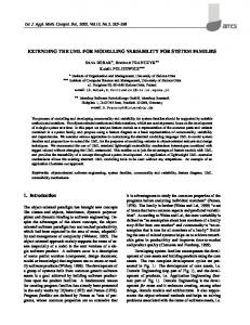
Although rules are powerful and popular knowledge representation method, not much research has been done in the area of visual modeling of rules. A UML-Based Rule Modeling Language (URML) [46] is one of the few modeling languages that allows users to design rules in a visual way. It is based on UML class diagrams and extends UML metamodel by adding a rule notion and its visual notation. The language supports different kinds of rules. An example of a production rule for deleting an object is shown in Fig. 1 (The rule can be read as follows: If a customer has a voucher whose value is greater than 4 and the customer’s shopping cart has a discount of more than 10, then delete the voucher.). In URML every rule is expressed graphically as circle with rule identifier. Depending on the kind of rule, incoming arrows can express rule conditions
Figure 1. An example of URML model for production rule
or triggering events, and outgoing arrows express rule conclusions or produced actions. URML models can be modeled with a dedicated tool – Strelka9 [47]. Another tool for visual rule modeling is Visual Rules Suite10 , where rules are presented in block-schema like style. Moreover, modeling of flow rules and decision tables is provided. Although this approach provides graphical notation and ensures readability, it forces the use of a dedicated notation which is not UML-compliant. In addition to the discussed tools, it is necessary to mention apropriate OMG standards. The Semantics of Business Vocabulary and Business Rules (SBVR) [15] is one of the existing standards, which concerns rules for modeling business concepts. It intends to be the basis for describing complex entity in a declarative formal way and detailed natural language description, suitable for machine interpretation. Another standard is Production Rule Representation (PRR) [48], which defines the metamodel for production rules and aims at incorporating production rules into UML models to support the separation of business logic from business objects. Because these solutions are developed by a group of business vendors, the standards are vendor-neutral and do not define the visual representation for rules. Another approach to define rules in UML is a profile for rules which redefines the original UML semantics for a specific application area. An example of such a UML profile, a profile for modeling Semantic Web Rule Language (SWRL) [49] rules, is presented in [50]. Using this profile, it is possible to model rule-extended ontologies. Although this approach does not extend the UML notation, it extends its semantics and forces user to use particular stereotypes. There is also a new proposal of using SWRL for defining constraints with rules imposed on 9
10
http://rewerse.net/I1/oxygen.informatik.tu-cottbus.de/rewerse-i1/@q= strelka.htm http://www.visual-rules.com
models [51]. However, this is yet another approach, where only textual notation is used. To summarize, exitsing solutions to rule visualization with UML either fail to scale up with the growing number of rules or introduce custom, non-standard artifacts to the existing notation11 . In the existing notations (both textual, such as OCL, and visual ones, such as URML), every rule requires writing each rule as separate sentence or separate diagram. 3.3
Quality of UML Models and Knowledge Base
In practical software and knowledge engineering (KE), the problem of quality assurance is an essential issue. In SE it concerns UML models whereas in KE mostly rule bases (see [32] for a recent overview, and [52] for a very recent study). Various distinctive approaches have been applied to validate UML models [53]. There are several different methods, but the mainstream ones are based on transforming into formal models (e.g. Promela [54], Petri nets [55], Z [56] and Lustre [57], Description Logic [58], LOTOS [59]). Such transformed models can be then validated and verified. However, the lack of precise UML semantics makes UML models difficult to validate. Thus, in the existing solutions, not the complete UML is considered, but mostly one type of diagrams. Moreover, there is a stage of improving the semantics of models for a particular purpose. One of the tools for verifying UML models, vUML [54], supports validation and analysis of the UML state chart diagrams. In this approach, UML diagrams are transformed to the Promela12 specification, which is the input language to the model checker SPIN13 . Then, the model checker is used to perform the verification. In case of finding an error in the model, the tool is able to create a UML sequence diagram, which fixes the error in the model. A slightly different approach to UML models verification is the adaptation of Petri nets. According to [55], net models can be flexibly adapted to drive simulations, because of a mature theoretical base. Moreover, they benefit from their graphical notation and clearly defined semantics. In this approach, UML state chart diagrams are used to specify the system behavior. The model is mapped to Colored Petri net notation. A Design/CPN tool supports the automated generation of colored Petri net models based on UML models. The tool provides a user interface, which allows users to control the visualization of the simulation result. Based on design models, it is possible to create simulation scenarios. Thanks to simulation, potential design errors can be revealed in the early stages of system development. A similar approach is based on the concept of translating the UML statechart model into graph transformation system [60]. Another attempt to provide a formal foundation for UML is translation UML models to mathematical models using formal languages, e.g. Z notation [56] or 11
12
13
While an introduction of custom UML extensions for rules might become a must, currently it strongly limits the use of existing UML tools. http://www.dai-arc.polito.it/dai-arc/manual/tools/jcat/main/node168. html http://spinroot.com/spin/whatispin.html
Lustre [57]. Such formal specification allows theorem provers or test generators to validate models. In [61], UML as a semi-formal language is mixed with formal ones (Z, Lustre). The static part of a UML model is translated into Z in order to check constraints on the classes and relations. From the dynamic part of the model an executable Lustre specification is extracted. This can be animated, tested or validated by the Lutess14 environment. Recently, a new approach to automated consistency checking of UML models has been proposed in [58]. This approach uses a plug-in integrated into Poseidon for UML called MCC+15 , which deals with inconsistencies in UML models. In order to detect these inconsistencies, the tool translates the metamodel and the user designed model into Description Logic [62] (DL) and uses a DL-based reasoning engine Jena16 . Another method of assuring quality of software is based on testing. There is research that focuses on automated generation of test cases based on UML models. Such an approach is presented in [25]. It is supported by a tool called MACT17 (Model-based Aspect/Class Testing) which can generate executable test code from state models for classes. To summarize, it can be observed that on the one hand, software quality analysis based on UML models is a mature field, where number of methods and tools are available. On the other hand, the integration of business rules with UML-based models is a relatively new area. Due to large differences between semantics of rules and UML diagram types this area needs more research with practical results.
4
Knowledge Representation in the HeKatE Design Process
Hybrid Knowledge Engineering18 (HeKatE) [20] is a software design methodology based on Knowledge Engineering (KE) methods. It aims at incorporating some well-established KE tools and paradigms into the domain of SE [63]. This methodology has been recently further extended into to Semantic Knowledge Engineering (SKE) [21] approach which also covers the design of Semantic Web and SE models. HeKatE and SKE use the eXtended Tabular Trees representation (XTT version 2 or XTT2) [64,65,66,67] for business rules modeling and processing the business logic. This hybrid knowledge representation forms a transparent and hierarchical visual model of the decision tables linked into a tree-like structure. There are two levels of abstraction in the XTT2 model: – the lower level – where a single knowledge component defined by a set of rules working in the same context is represented in a single XTT2 table, 14 15 16 17 18
http://membres-lig.imag.fr/ledru/IMAGatFM99/LutessFM99.html http://www.dcc.uchile.cl/~jsimmond/mcc/mcc.html http://jena.sourceforge.net http://www.homepages.dsu.edu/dxu/research/MBT.html http://hekate.ia.agh.edu.pl
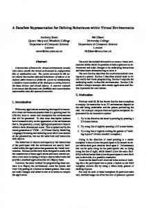
– the higher level – where the structure of the whole XTT2 knowledge base (consisting of XTT2 tables) is considered. Such knowledge representation provides high data density: every row of a table corresponds to a single rule, but the table allows to visualize only specific values of attributes. XTT2 model represents rules in a formal way, using the ALSV(FD) logic. It is much more expressive than the classic (mostly propositional) rule languages, e.g. it allows for formal specification of non-atomic values in rule conditions [20]. The set of linked tables represents the complete rule-based knowledge base in a form of an inference network (the name XTT has been kept for compatibility reasons). Several inference scenarios are considered [35], including data and goal driven. An exemplary decision table with an illustration of main phases of the HeKatE methodology is shown in Fig. 2. In the first phase the structure of the rule base is identified. It corresponds to different contexts of the system operation, or is related to different knowledge components. In the second phase decision tables grouping rules that form knowledge components (represented as extended decision tables) are designed. Apart from the visual representation, the model has a complete formal description using the ALSV(FD) calculus [20]. The last phase includes the serialization of the model to the HeKatE Meta Representation language (HMR) form which can be directly executed and verified, as well as the HeKatE Markup Language (HML) form suitable for knowledge exchange and translation. A CASE design tool called HeKatE Qt Editor (HQEd) [68,69] supporting the XTT2 visual design method has been developed for knowledge modeling in the HeKatE methodology. Based on the visual XTT2 model, an algebraic humanreadable textual representation of the rule base is generated. It is specified in HMR, and forms an executable business logic prototype. The HeKatE RunTime (HeaRT) engine [70] provides a unified run-time environment for the HMR-based rule bases. HeaRT is an inference engine supported with optional C/Java runtime to be integrated with Java or C-based application. HeaRT directly interprets HMR files which can be executed and debugged. Moreover, it provides an on-line formal analysis of the rule base wrt. to selected formal properties, such as rule subsumption, rule base completeness or determinism of the system (see [71,20,72] for more details). The designed XTT2 model can be serialized and stored in the XML-based HeKatE Markup Language (HML)19 format. Therefore it is possible to use it for translation using Extensible Stylesheet Language Transformations (XSLT). HeKatE Translation Framework (HaThoR) is an XML-based framework for knowledge translation from/to HML to other formats. Non-trivial translations include network firewalls [73], and more recently semantic wiki systems [74,75]. A part of the research, presented in this paper, is an implementation of the HaThoR translators. The HeKatE/SKE approach, with its smooth transition between the design and implementation, is similar to the MDA [76], especially to the formalized 19
https://ai.ia.agh.edu.pl/wiki/hekate:hekate_markup_language
Figure 2. HeKatE design methodology phases
transition from the PIM to the PSM model, However, in methodology there is no platform specific model, because both the HML and HMR models are portable. Let us now proceed to the formulation of the UML representation corresponding to the XTT2 model. This representation uses standard UML diagrams to model the XTT2 semantics.
5
UML Representation of XTT2
The research presented in this section is a result of several years of development. Preliminary results have been previously presented in [63,77,78,79]. In the XTT2 representation rules working in the same context (having the same attributes) are grouped in decision tables [29]. Therefore, the fundamental issue for modeling XTT2 in UML is the representation of an XTT2 table. Although the UML Superstructure Specification ver. 2.2 [80] in Appedix E introduced Tabular Notation for Sequence Diagrams, it is not a representation for any custom
table. It is rather a serialization of Sequence Diagram to the tabular form, which can not be used for representing any XTT2 table in particular. A representation of such a table should use one of the behavior diagrams, such as a Use Case Diagram, an Activity Diagram or a State Machine Diagram, as well as one of Diagrams of Interaction (a Sequence or Collaboration Diagram). According to the discussion in [77] State Machine Diagrams and Activity Diagrams seem to be the best UML candidates for rule modeling. State Machine Diagram shows the possible states of the object and the transitions that cause a change in the state. It focuses on an object undergoing a process (or on a process as an object). Activity Diagram, in turn, focuses on the flow of activities involved in a single process and shows the dependencies among them. Several preliminary approaches of such UML models of XTT2 have been presented in report [79]. Such a representation is not as expressive as the XTT2 itself. Especially, in case of larger systems with a huge number of rules, using the UML poses practical problems. However, it is possible to use it to express rules in case of smaller systems. 5.1
The XTT2 Model Representation
Our proposal of XTT2 representation in UML uses Activity Diagrams to express the XTT2 model (see [77] for more details on other modeling attempts). These diagrams are related to flow diagrams and illustrate the activities in the system.
Figure 3. The lower level model example: an XTT2 table
At the Lower Level of the knowledge base a single XTT2 table is represented. An example of a UML representation (corresponding to the XTT2 table in Fig. 3) is shown in Fig. 4. In the proposed UML model of the XTT2 table the following node types are used: – – – – – –
Activity Parameter – the parameter representing an XTT2 attribute, Action – sets the value of the output parameter, Decision Node – enables checking distinct values of input parameter, Merge Node – corresponds to logical or operation for flows, Fork Node – enables to branch out and manifold the flow, and Join Node – corresponds to logical and operation for flows.
Every XTT2 attribute is represented by an (input or output) Activity Parameter node. The whole Activity resembles a logical gate system, where Merge/Join
Figure 4. The lower level model example: the UML representation of the XTT2 table from Fig. 3
Nodes behave like logical or /and gates. Values of attributes are checked in guard conditions by the Decision Nodes, and values of output parameters are set by Actions. In more complex cases, there is a possibility of different transitions from one table. In such a situation the new "transition" output Activity Parameter is introduced. This is shown in Fig. 5. The diagram corresponds to the exemplary Table 1, where Par_ are attribute names.
Par1 Par2 ParX ParY transition a b c g → tab2 a f d h → tab2 e f c i → tab3 Table 1. The exemplary XTT2 table
At the Higher Level the whole XTT2 model consisting of linked tables is represented. In the model, every table has a corresponding Action, which calls the behavior modeled at the lower level. These Actions are connected as previously at the lower level model. If an action has an Output Pin on its output, it means that the corresponding table has transitions to more than one table (in accordance with each distinct value of "transition" attribute from the lower level model). An example of such representation is shown in Fig. 6.
Figure 5. The lower level more complex model example
Figure 6. The higher level model example
5.2
Metamodel of the XTT2 Model
The metamodel is one of methods used for defining the syntax of the visual language [81], as well as for defining the structure of the system [82]. For example, the abstract syntax of UML is defined by the UML metamodel. The proposed model uses only a subset of UML artifacts and their relationships. Thus, the metamodel of this model constitutes a subset of UML Activity Diagram metamodel [80] with additional constraints imposed. Fig. 7 shows the metamodel of the UML representation for XTT2 diagrams. The presented metamodel is not yet precisely defined, since UML diagrams themselves are typically not detailed enough to describe every aspect of a specification. To ensure the accuracy of models, some additional constraints for the metamodel have to be provided using OCL. The metamodel does not enforce the order of nodes. It can be observed in the metamodel that it allows for generating models which do not match the XTT2
Figure 7. Metamodel for XTT2 diagrams
ones. The required order of nodes for the XTT2 model at the lower abstraction level is as follows (nodes which can occur optional are in brackets): Activity Parameter Node → Decision Node → (Fork Node) → Join Node20 → Fork Node21 → (Merge Node) → Action → (Merge Node) → Activity Parameter Node. At the higher abstraction level, the required order of nodes for the XTT2 model differs from the one stated above and is as follows: Activity Parameter Node → (Fork Node) → * (Join Node) → Action → ((Decision Node)22 → back to * ) → (Fork Node) → Activity Parameter Node. The solution for the enforcement this node order is to use constraint expressions in OCL (these expressions have been described in more detail in [79]). Moreover, the higher level model of XTT2 uses an additional Output Pin artifact 20 21
22
Element occurs when there is more than one input Activity Parameter node. Element occurs when there is more than one output Activity Parameter node or there is the transition parameter node (which enables the transition to different tables). Element occurs when previous Action has Output Pin.
(which is one of the UML standard artifacts; however not used in the lower level model of XTT2). Thus, the XTT2 metamodel from Fig. 7 has to be extended by introducing an additional UML standard element, as shown in Fig. 8.
Figure 8. Introducing Output Pin to the metamodel of XTT2
The obtained UML representation of XTT2 can be serialized to the XMLbased XMI format23 . Using it, it is possible to define practical model traslations.
6
Model Translations
XML Metadata Interchange (XMI) [83] is an XML-based OMG standard for exchanging metadata information. Although it can be used to represent any model or meta-model which is MOF compliant, it is mostly applied to encode UML models for model exchange between various tools. Despite this fact, there is still a variety of XMI formats and many UML tools store models in XMI uses its own tool-specific XMI format. Moreover, the XMI Specification [83] does not define XML tags for every UML artifact, but specifies how to create them for the metamodel concepts [84]. For the purpose of the implementation the newest XMI 2.1 version was adapted. This version is currently supported by several UML tools (e.g. Altova UModel 24 , Visual Paradigm for UML25 ). The detailed description of the XMI tags that represent UML artifacts used in the UML representation of XTT2 can be found in [79]. Although XMI is predominantly used to exchange model data between different UML tools [85], in this research it is considered as a format for serializing models for further translation and code generation. HML [68] provides a notation for XML serialization of the HeKatE rule base (DTD and examples of HML available at http://ai.ia.agh.edu.pl/wiki/ hekate:hades). HML is used for storing the knowledge in the HeKatE project in a machine-readable format. This can be used to interchange knowledge between the tools from the HaDEs framework [68]. The HML code is divided in three 23 24 25
http://www.omg.org/spec/XMI. http://www.altova.com/umodel.html. http://www.visual-paradigm.com/product/vpuml.
subsets. In this research only the Attribute Markup Language for describing rule attributes (ATTML) and the XTT2 Rule Markup Language for the XTT2 structured rule representation (XTTML) subsets are used for the XTT2 translations. Next, the following two subsections discuss creating translators from an XMI representation of the presented XTT2 model to the HML representation and reverse. They present algorithms to be used during implementation of these translators. 6.1
Translation Algorithm from XMI to XTT2
In the XTT2 UML representation (serialized to XMI), UML artifacts have their own semantics, and the translation to XTT2 (serialized to HML) is not simple. It is not sufficiant to perform the mapping of elements (between XMI and HML) – additional transformations have to be done. Fig. 9 shows the flowchart of the translation. The algorithm for the lower level representation is as follows. For every table: 1. Name of the table is saved. 2. Activity Parameter Nodes become attributes of the table. 3. In order to transform the rules, there is a need to simplify the representation. This can be done in the following way (the process is illustrated in Fig. 10): (a) For every input Activity Parameter Node, its id is stored in the ref attribute of the following Decision Node and the Parameter Node is removed. (b) For every Object Flow with the source in a Fork Node, the source of the incoming edge of the node becomes the source of the Object Flow (with nested guard element preserved) and the Fork Node is removed. (c) For every Object Flow for which the target element is a Merge Node, the target of the Merge Node becomes a target of the Object Flow, and the Merge Node is removed. (d) For every output Activity Parameter Node, its id is stored in the ref attribute of the precedent Action node, and the Parameter Node is removed. 4. After the simplification of the model, it is much easier to transform the UML representation of rules to HML. (a) If there is more than one input Activity Parameter, Join Nodes become rule elements in the following way. For every Join Node: i. every guard value in the incoming edges to the Join Node becomes the expression in the condition part for the proper rule attribute. ii. every action name in the outgoing edge of the Join Node becomes the expression in the decision part for the proper rule attribute. (b) If there is only one input Activity Parameter, Object Flows which have the source in a Decision Node become rule elements in the following way: i. every guard value in the flow becomes the expression in the condition part for the proper rule attribute.
START
is a not translated lower level table?
Higher level Table Simplifying (5a) (removing Join Nodes)
No
Yes Higher level Table Simplifying (5b) (removing Decision Nodes)
Saving the table name (1)
Translation of input Activity Parameter Nodes to input attributes (2)
Translation of output Activity Parameter Nodes to output attributes (2)
Translation: Action with Output Pin to tabref HML element (6)
Translation: Action without Output Pin to tabref HML element (6)
Table Simplifying (3a) (removing input Parameter Nodes)
STOP
Fork Nodes occure?
Yes Table Simplifying (3b) (removing Fork Nodes)
No
Table Simplifying (3c) (removing Merge Nodes)
Table Simplifying (3d) (removing output Parameter Nodes)
more than 1 input Parameter Node?
Yes Translation: Join Node to rule HML element (4a)
No
Translation: Object Flow (with source in the Decision Node) to rule HML element (4b)
Figure 9. Flowchart presenting the translation algorithm from UML (XMI) to XTT2 (HML)
ii. every action name in the outgoing edge of the Join Node becomes the expression in the decision part for the proper rule attribute.
Figure 10. The proces of simplification of the table representation
At this stage of the algorithm the table representation is finished. However, there are no links between tables. The algorithm for the higher level representation is: 5. In order to simplify transformation, there is a need to simplify the tree of tables representation. This can be done in the following way (see Fig. 11): (a) For every Object Flow of which a target element is a Join Node, a target of the outcoming edge of the Join Node becomes the target of the Object Flow, and the Join Node is removed. (b) For every Object Flow which has its source in a Decision Node, the source of the incoming edge of the Decision Node becomes the source of the Object Flow (a nested guard element is preserved), and the Decision Node is removed. 6. Following the simplification of the model, translation is straightforward. For every Action: – without Output Pin, the id of the following table is set as the transition target for every rule in the table. – with Output Pin, ids of the following tables are set as the transition targets for proper rules in the table, according to the guard in the Object Flow. Next, the reversed algorithm is described. 6.2
Translation Algorithm from XTT2 to XMI
The translation algorithm from XTT2 to XMI is more complicated than the previous one. This section contains the refined version of the algorithm presented
Figure 11. The proces of simplification of the tree of tables representation
in [77] for XTT2 tables. Because of the semantics of UML artifacts, some complex transformations have to be done. The algorithm for the lower level representation is as follows (the algorithm is illustrated in Fig. 12). For every XTT2 table the Activity is created, and: 1. All condition attributes become input Activity Parameter Nodes, and decision attributes become output Activity Parameter Nodes. 2. For each condition attribute (input Activity Parameter Node) the Object Flow goes to a decision node, and for each unique value of the attribute: (a) the Object Flow with this unique value as a Guard condition is introduced, (b) if the value occurs frequently, the flow is finished with a Fork Node. 3. If there is more than one condition attribute, for each XTT2 rule a Join Node is created, and: (a) for each condition attribute the proper Object Flow is connected to the Join Node (if the value of the considered condition attribute occurs frequently, the flow starts from the proper Fork Node), (b) depending on the number of decision attributes: i. if there is only one decision attribute: the proper Object Flow starts from the Join Node and is connected to the Action having a value corresponding to the decision attribute (if the value of the decision attribute occurs in the table more than once, a Merge Node is introduced and the connection is through this Merge Node),
Figure 12. The translation algorithm from XTT2 to XMI for the lower level representation
ii. otherwise: a Fork Node is introduced and the Object Flow from the Join Node to this Fork Node is created. 4. If there is more than one decision attribute, from each Fork Node (corresponding to the XTT2 rule), for each decision attribute the proper Object Flow from the Fork Node is introduced and connected to: (a) the proper Merge Node, if the value of the decision attribute occurs in the table more than once (if the proper Merge Node does not exist yet, it should be introduced). (b) the Action (having a value corresponding to the value of the decision attribute in the rule). 5. For every decision attribute, outputs of Actions (having the values of particular attribute) are connected to a Merge Node and an Object Flow from the Merge Node leads to the corresponding output Activity Parameter Node. The algorithm for the higher level representation is as follows. The activity diagram for the whole system is created, and: 1. for every XTT2 input and output system attributes, corresponding input and output Activity Parameter Nodes are created.
2. for every XTT2 table, the CallBehaviorAction is created, and: – if more than one table has the link to this table, a Join Node is created and the proper Object Flows from those tables to the Join Node are created, – if only one table has the link to this table, an Object Flow from that table to this table is created, – if the condition attribute of this table is the input system attribute, the Object Flow from the corresponding Activity Parameter Node to this table is created (if the attribute is the condition attribute in more than one table, a Fork Node is introduced and the connection is through this Fork Node). 3. For every output Activity Parameter Node an Object Flow from the proper CallBehaviorAction is created, according to the decision attributes of the XTT2 tables, and: – if the attribute is the decision attribute in more than one table, a Join Node is introduced and the connection is through this Join Node, – if the attribute is not the only one decision attribute in the table, a Fork Node is introduced and the connection is through this Fork Node. Next, the implementation of the algorithms is discussed. 6.3
Algorithm Implementation
The UML representation of XTT2 is serialized to an XMI file, and an XTT2 model is stored in the HML file. Because both are XML compliant, the implementation of proposed translation algorithms is done with use of XSLT. XSLT [86] allows transforming an XML document into other XML document or another format. It describes how to transform elements of one model into elements of another model and enables to convert one model into another. Although there are some disadvantages of using XSLT (such as poor readability or poor errors information), among various methods, XSLT is recommended for a couple reasons [87,88]. It should be used when both source and target formats are XML-based and there is a need for matching elements from the source document with using its structure and associating them with the target document structure. But the key advantage of using XSLT is that there are many XSLT engines available. Thus, there is no need to implement an evaluation engine. Both translators have been implemented in XSLT and are available from the HeKatE website at http://ai.ia.agh.edu.pl/wiki/hekate:hathor. Their use is presented on a case study discussed in the following section.
7
Cashpoint Case Study Design
To evaluate the discussed approach against the problems defined in Section 2 a practical control system case study is presented. The business logic is modeled
with rules represented in XTT2. Then, the UML representation is given for the BL model. Finally, the UML design for the system user interface (View) and the controller connecting it with the model is given. Basing on this, a critical overview of the approach is given in the next section. The case study considered here is based on a cashpoint use case study described in [89]. In this case study, the system is composed of a till which can access a central resource containing the detailed records of customers’ bank accounts. A till is used by inserting a card and typing in a Personal Identification Number (PIN) which is encoded by the till and compared with a code stored on the card. After successfully identifying themselves to the system, customers may either make a cash withdrawal or ask for a balance of their account to be printed. Withdrawals are subject to a user resources, which means the total amount that user has on account. Another restriction is that a withdrawal amount may not be greater than the value of the till local stock. Tills may keep illegal cards, i.e. after three failed tests for the PIN. This case is one of the rule-based systems studied as benchmark cases in HeKatE (see http://ai.ia.agh.edu.pl/wiki/hekate:cases:hekate_case_cashpoint: description for a complete design). It is selected for the presentation in this paper, since it presents a simple, yet real-life system. Moreover, it allows for a transparent separation of the main system logic and its interfaces. Therefore it is suitable for the application of the MVC pattern and our approach. The design studied here is based on the original independent specification [89]. Let us here consider the XTT2 rule model for this problem as shown in Fig. 13. The business logic is decomposed into several decision tables grouping business rules working in the same context, e.g. user authorization. The network of decision tables represents the complete model for the system. The visual design process for the XTT2 rule representation is supported by the HQEd [69] editor. The model can be serialized to the human-readable HMR representation suitable for instant verification and direct execution by the HeaRT [70] engine. The rule verification process can be performed on-line from the visual editor using the integration protocol with HeaRT. In the listing below, part of the modified CashPoint model have been verified by checking table completeness: Starting HeaRT... Copyright (C) by G. J. Nalepa and A. Ligeza 2004-2006 and the HeKatE Project 2006-2009 HeaRT is free software: you can redistribute it and/or modify it under the terms of the GNU General Public License as published by the Free Software Foundation, either version 3 of the License, or (at your option) any later version. ?- [’hekate_case_cashpoint-clb.pl’]. ?- vcomplete(’authorization’). State: pinDifference State: authorizated State: failedAttempts ?- vcomplete(’cashPointActivityDetermining’). State: authorizated State: failedAttempts State: userRequestedAction State: udAmountDifference State: cdAmountDifference ’In Table1 uncover state: ’(authorizated) in ([0.0])(cdAmountDifference) in ([-100000.0 to -1.0])(failedAttempts) in ([4.0 to 5.0])(udAmountDifference) in ([-100000.0 to -1.0])(userRequestedAction) in ([withdraw])’’ ’In Table1 uncover state: ’(authorizated) in ([0.0])(cdAmountDifference) in ([-100000.0 to -1.0])(failedAttempts) in ([4.0 to 5.0])(udAmountDifference) in ([-100000.0 to -1.0])(userRequestedAction) in ([balance])’’ ’In Table1 uncover state: ’(authorizated) in ([0.0])(cdAmountDifference)
in ([-100000.0 to -1.0])(failedAttempts) in ([4.0 to 5.0])(udAmountDifference) in ([0.0 to 1e+06])(userRequestedAction) in ([withdraw])’’ ’In Table1 uncover state: ’(authorizated) in ([0.0])(cdAmountDifference) in ([-100000.0 to -1.0])(failedAttempts) in ([4.0 to 5.0])(udAmountDifference) in ([0.0 to 1e+06])(userRequestedAction) in ([balance])’’ ’In Table1 uncover state: ’(authorizated) in ([0.0])(cdAmountDifference) in ([0.0 to 1e+06])(failedAttempts) in ([4.0 to 5.0])(udAmountDifference) in ([-100000.0 to -1.0])(userRequestedAction) in ([withdraw])’’ ’In Table1 uncover state: ’(authorizated) in ([0.0])(cdAmountDifference) in ([0.0 to 1e+06])(failedAttempts) in ([4.0 to 5.0])(udAmountDifference) in ([-100000.0 to -1.0])(userRequestedAction) in ([balance])’’ ’In Table1 uncover state: ’(authorizated) in ([0.0])(cdAmountDifference) in ([0.0 to 1e+06])(failedAttempts) in ([4.0 to 5.0])(udAmountDifference) in ([0.0 to 1e+06])(userRequestedAction) in ([withdraw])’’ ’In Table1 uncover state: ’(authorizated) in ([0.0])(cdAmountDifference) in ([0.0 to 1e+06])(failedAttempts) in ([4.0 to 5.0])(udAmountDifference) in ([0.0 to 1e+06])(userRequestedAction) in ([balance])’’ true.
The verification shows uncovered states, i.e. incomplete rule specification26 . HeaRT can also perform determinism checks as well as partial system minimalization (see [20] for more details).
Figure 13. The XTT2 model for the CashPoint use case study
The XTT2 model is also serialized to the XML-based HML notation suitable for the XSLT translation. Using XTT2UML XSLT translator it can be transformed from HML to XMI and then opened in a UML design tool. A set of diagrams for the UML model of the presented XTT2 cashpoint model is shown in Fig. 14. These diagrams correspond to the previously defined decision tables. The domain model for the rule attributes can be observed in Fig. 15. The design conforms to the MVC pattern. In this case the model is responsible for 26
In fact the original case study does not have this deficiency. To show the possibility of uncovered states discovering, the model domain was changed and in the number of failed attempts was increased to 5.
storing domain data (see Fig. 15) as well as the system behavior (see Fig. 14). The detailed behavior description allows for responding to requests concerning information about the system state.
Figure 14. The UML representation of the CashPoint XTT2 BL Model
The view part of the system is responsible for a GUI (Graphical User Interface) and the user interaction. This separation of the view from the model allows for independent development and easy substitution of each layer. The exemplary view implementation specification is shown in Fig. 16. The GUI for this implementation is shown in Fig. 17. It is a real-life example implemented using the Qt library (see http://www.trolltech.com) that heavily uses the MVC architectural pattern for application design. For brevity, in this paper we omit the detailed specification of the controller. However, the logic of its behav-
Figure 15. The UML representation of the domain for the CashPoint XTT2 BL Model
ior is presented in Fig. 18. Using features provided by Qt (or other application frameworks), it has been easily implemented.
Figure 16. The UML model of the View for the CashPoint application
It is worth noting that there is also a possibility of translating backwards, from the UML model to the XTT2 model. In this case, the UML model has to be defined and designed in an UML tool, which enables generation of the XMI code. The model serialized to XMI can be translated using the UML2XTT2 XSLT translator to the HML representation, which allows for refining the design in HQEd and verification with HeaRT. It can be observed that this benchmark HeKatE case study has 11 rules, from which 6 constitute the final decision table. To show the quantitative difference between compared notations, let us observe that the final XTT2 decision table (cashPointActivityDetermining) has 6 rules and 6 attributes. This makes 36 cells with values in the decision table to fill in. In the presented UML model there
Figure 17. The Qt GUI for the CashPoint application (PIN, Amount and Action Windows)
is no redundancy of attribute values, therefore there is only 21 various values to fill in. It is worth noting that in textual notations, such as OCL, this would require the use of every 36 values and writing separate rules. In URML models, in turn, this would require separate model for each rule.
8
Evaluation
The evaluation of our approach is given w.r.t. the visual representation and the effectiveness of the design. 8.1
UML Representation Evaluation
The proposed UML model for rule-based system is MOF compliant. It does not introduce any custom element, but uses only standard UML artifacts. This allows a user to use any of the existing UML tools which support model exporting to XMI. Although the model is not similar to the original XTT2, it shall be intuitive when one knows either the UML activity diagram semantics or the electronic logical gates (which perform the logical operations on logic inputs and produce a logic output). This representation, as other solutions mentioned earlier, does not scale well. When the number of rules in the table grows, the diagram becomes poorly readable. Due to the fact that visual rule representation faces the scalability problem, so in this field there is still space for research. Although there exist methods for designing single rules, designing rule groups constitutes a different problem. Groups of similar rules often can be modeled as a decision table and if it comes to readability, tables seem to be irreplaceable. Hence, they are so widely used in KE. Unfortunately, decision tables are not integrated with UML. The representation presented in this paper constitute an approach to integration a rule-based model with UML system specification. This allows a user to model decision tables and the whole structure of the knowledge base in UML. The representation tries to explore and efficiently use existing UML diagrams. Moreover, it does not extend UML semantics. In contrast, rule representations for UML-centric solutions, such as PRR, UML profile for rules, or URML, relay on either extending or
Figure 18. The UML behavioral model of the Controller for the CashPoint application
redefining the original UML semantics. Moreover, they aim at detailed modeling of single rules, thus they do not provide an efficient way for visual modeling of groups of rules. We evaluated our methods using selected benchmark cases from the HeKatE project. Our results summarized in Table 2 clearly show that for the benchmark cases our method requires at least 20% less values to be used than XTT2. As URML requires separate diagram for each rule, and our method requires separate diagrams for each table and one diagram for the whole system, this also reduces a user workload (see Table 3). Moreover, in Table 4, the quantitative comparison of the XTT2 and Drools methods for the selected benchmark cases is shown. To summarize, the presented UML representation has several advantages: – It uses only standard UML elements, so any UML tool (that supports XMI generation) can be used for modeling the system. – In the model there is no redundancy of attribute values as it is in XTT2 table (see comparison in Table 2). – The model transparently shows inputs and outputs of the system. – Decomposition of the rule base is provided through a bi-level hierarchy of diagrams in the model: the lower level model for visual rule set designing and the higher level model which stores the knowledge about control. This
Benchmark cases CashPoint Thermostat Cardio Health Hello Upsell PL LI
Rules 11 18 17 8 8 15 57
Tables 5 4 7 3 3 3 11
XTT2 values UML rep. values % less 51 36 29% 48 36 25% 56 43 23% 32 25 22% 24 19 21% 48 38 21% 151 116 23% Average % less values: 23% Table 2. The evaluation of the presented UML representation of XTT2
Benchmark cases CashPoint Thermostat Cardio Health Hello Upsell PL LI
URML diagrams UML diagrams % less 11 6 45% 18 5 72% 17 8 53% 8 4 50% 8 4 50% 15 4 73% 57 12 79% Average % less values: 60% Table 3. The comparison of the number of diagrams for the benchmark cases in URML and the proposed UML representation for XTT2
Benchmark cases CashPoint Thermostat Cardio Health Hello Upsell PL LI
XTT2 cells Drools cells % less 51 84 39% 48 60 20% 56 62 10% 32 59 46% 24 28 14% 48 59 19% 151 240 37% Average % less values: 26% Table 4. The comparison of the number of cells in the XTT2 tables to the Drools tables for the benchmark cases
allows for creation of more complex XTT2 trees, without the risk of losing readability and to ensure efficiency of the system. It should also be pointed out that the UML representation for XTT2 seems to be more useful when the rule-based logic is designed with XTT2 and then translated to UML. The reverse translation (from UML to XTT2) while fully possible seems to be less useful in practical design, since the semantics of XTT2 speeds up the rule design process. On the other hand, it could prove valuable in cases where there are some existing Business Logic models in UML activity diagrams. 8.2
Design Approach Evaluation
Our approach aimes at solving the three problems pointed out in Section 2. With regard to the rule visualization problem, it can be observed that XTT2 offers an expressive visualization for modularized rule bases superior to these available for classic rule solutions mentioned in Section 3. Moreover, visual specification can be directly executed and easily integrated into the rest of the application. The entire design process is based on UML, including the specification of application logic (that is modeled in UML in respect to the UML representation of XTT2). Because of the direct translation between XTT2 and UML representation, and the possibility of automatic logic implementation, the problem of the design representation mismatch is also addressed. The proposed UML representation uses only standard UML artifacts and allows for representing whole decision tables, not just single rules like in the case of URML. Its weakness is the visual scalability issue – the size of activity diagrams grows with the size of decision tables. On the other hand, this follows the limitations of the diagrams provided with UML 2.0. Finally, because the rule model is expressed in a formal way, the HeKatE methodology provides an online verification of the model, thus dealing with the quality assurance problem. The provided verification checks are optimized for the rule representation. Since the XSLT model translation preserves the semantics, it does not alter any formal properties of the model. Thus, the obtained UML model preserves the previously verified formal properties (e.g. completeness or determinism).
9
Concluding Remarks
In this paper, practical challenges of using Knowledge Engineering methods in the Software Engineering practice are discussed. The focus of the paper is on the visual design methods for software applications. The assumption is made that the UML-based representation should capture the whole system design. On the other hand, the core parts of the business logic could be designed in an optimal way using the business rules approach. In fact it has been a common approach in recent years. However, the approach has several important limitations
concerning an appropriate visual design specification for business rules. Such a representation should be semantically compatible with UML, while keeping all the qualities of the rule-based model. At the same time the quality issues of the resulting hybrid model should be considered as well as appropriate knowledge integration problems addressed. The proposed solution to these problems and the original contribution of this paper is the idea of using the XTT2 rule representation to design the application core logic. This logic is integrated with the remaining parts of the application using the MVC architectural pattern. Moreover, the XTT2 rule design can be translated to a corresponding visual UML model. Simultaneously, formal properties of the designed business rules logic can be instantly verified. In the presented rule-based approach the core logic of the application (the model) is clearly identified and separated. The model is built in a declarative way, which makes the design transparent and easier to follow, develop and update in case of the changing user requirements. Thanks to these features the approach increases the agility of the design process. Based on the evaluation presented in the paper, it can be observed that this solution is superior both to existing visual rule notations, as well as visual design tools for rules. It does not extend any custom UML artifacts and can be used with standard UML tools. The resulting UML design can be analyzed by software designers familiar with UML. On the other hand, it can be easily refined by application architects using the business rules semantics. Currently, the business logic model can be integrated with application interfaces using the HeKatE/SKE framework. In this case, the business logic is executed by HeaRT and linked with the interfaces on runtime. Future works include possible generation object-oriented code from the resulted UML model. In this case the complete application would be implemented in the same programming language (e.g. Java). Another direction is the evaluation of the ATLAS translation framework (http://www.eclipse.org/atl) from the Eclipse project that supports multimodel exchange. There is also an ongoing research within the Bimloq project (see http://bimloq.ia.agh.edu.pl) aiming at the translation of the XTT2 control structures to business processes [90].
Acknowledgements The authors wish to thank Dr. Joachim Baumeister for his important comments on the paper structure, as well as Dr. Joaquín Cañadas for his valuable insight on the metamodel formulation aspects. We also thank members of the GEIST group (http://geist.agh.edu.pl) led by Prof. Antoni Ligęza for their support in writing of this paper, including help with HeKatE tools. Special thanks are due to Weronika T. Adrian M.Sc. for providing valuable comments for the initial version of this paper.
References 1. Sommerville, I.: Software Engineering. 7th edn. International Computer Science. Pearson Education Limited (2004) 2. Weiss, G., Pomberger, G., Beer, W., Buchgeher, G., Dorninger, B., Pichler, J., Praehofer, H., Ramler, R., Stallinger, F., Weinreich, R.: Software Engineering – Processes and Tools. In: Hagenberg Research. Springer (2009) 157–235 3. OMG: Unified Modeling Language version 2.1.2. infrastructure. specification. Technical Report formal/2007-11-04, Object Management Group (2007) 4. Hunt, J.: Guide to the Unified Process featuring UML, Java and Design Patterns. Springer (2003) 5. Barbier, F., Aretxandieta, X.: State-based composition in UML 2. International Journal of Software Engineering and Knowledge Engineering 18 (2008) 987–1011 6. Object Management Group: Object Constraint Language Version 2.0. Technical report, OMG (2006) 7. Gamma, E., Helm, R., Johnson, R., Vlissides, J.: Design Patterns. 1st edn. Addison-Wesley Pub Co. (1995) 8. IEEE: 1016-2009 IEEE standard for information technology–systems design– software design descriptions. Technical report, IEEE (2009) 9. Burbeck, S.: Applications programming in Smalltalk-80(TM): How to use ModelView-Controller (MVC). Technical report, Department of Computer Science, University of Illinois, Urbana-Champaign (1992) 10. Biere, M.: Business intelligence for the enterprise. Prentice Hall PTR (2003) 11. Singh, I., Stearns, B., Johnson, M.: Designing Enterprise Applications with the J2EE Platform. 2nd edn. Prentice Hall (2002) 12. Lin, J.: An object-oriented development method for consumer support systems. International Journal of Software Engineering and Knowledge Engineering 19 (2009) 933–960 13. Ross, R.G.: Principles of the Business Rule Approach. Addison-Wesley Professional (2003) 14. von Halle, B.: Business Rules Applied: Building Better Systems Using the Business Rules Approach. Wiley (2001) 15. OMG: Semantics of Business Vocabulary and Business Rules (SBVR). Technical Report dtc/06-03-02, Object Management Group (2006) 16. Erl, T.: Service-Oriented Architecture (SOA): Concepts, Technology, and Design. Prentice Hall PTR (2005) 17. Cañadas, J., Palma, J., Túnez, S.: InSCo-Gen: A MDD tool for web rule-based applications. In Gaedke, M., Grossniklaus, M., Díaz, O., eds.: Web Engineering, 9th International Conference, ICWE 2009, San Sebastián, Spain, June 24-26, 2009, Proceedings. Volume 5648 of Lecture Notes in Computer Science., Springer (2009) 523–526 18. Panagiotou, D., Mentzas, G.: Leveraging software reuse with knowledge management in software development. International Journal of Software Engineering and Knowledge Engineering 21 (2011) 693–723 19. Cheeyang, Cho, E., Kim, C.: An integrated GUI-business component modeling method for the MDD- and MVC-based hierarchical designs. International Journal of Software Engineering and Knowledge Engineering 21 (2011) 447–490 20. Nalepa, G.J., Ligęza, A.: HeKatE methodology, hybrid engineering of intelligent systems. International Journal of Applied Mathematics and Computer Science 20 (2010) 35–53
21. Nalepa, G.J.: Semantic Knowledge Engineering. A Rule-Based Approach. Wydawnictwa AGH, Kraków (2011) 22. Baumeister, J., Freiberg, M.: Knowledge visualization for evaluation tasks. Knowledge and Information Systems (2010) 1–30 23. Nguyen, N.T.: Processing inconsistency of knowledge on semantic level. Journal of Universal Computer Science 11 (2005) 285–302 24. Ammann, P., Offutt, J.: Introduction to Software Testing. Cambridge University Press (2008) 25. Xu, D., Xu, W., Wong, W.E.: Automated test code generation from class state models. International Journal of Software Engineering and Knowledge Engineering 19 (2009) 599–623 26. Baumeister, J.: Advanced empirical testing. Knowledge-Based Systems 24 (2011) 83–94 27. Tadeusiewicz, R.: Introduction to intelligent systems. In Wilamowski, B.M., Irwin, J.D., eds.: Intelligent systems. The Electrical Engineering Handbook Series. The Industrial Electronics Handbook. Second edition edn. Boca Raton; London; New York: CRC Press Taylor & Francis Group (2011) 1–1–1–12 28. Giarratano, J., Riley, G.: Expert Systems. Principles and Programming. 4th edn. Thomson Course Technology, Boston, MA, United States (2005) 29. Ligęza, A.: Logical Foundations for Rule-Based Systems. Springer-Verlag, Berlin, Heidelberg (2006) 30. Giurca, A., Gasevic, D., Taveter, K., eds.: Handbook of Research on Emerging Rule-Based Languages and Technologies: Open Solutions and Approaches. Information Science Reference, Hershey, New York (2009) 31. Vermesan, A., Coenen, F., eds.: Validation and Verification of Knowledge Based Systems. Theory, Tools and Practice. Kluwer Academic Publisher, Boston (1999) 32. Ligęza, A., Nalepa, G.J.: Rules verification and validation. In Giurca, A., Gasevic, D., Taveter, K., eds.: Handbook of Research on Emerging Rule-Based Languages and Technologies: Open Solutions and Approaches. IGI Global, Hershey, New York (2009) 273–301 33. Nalepa, G.J.: Languages and tools for rule modeling. In Giurca, A., Gasevic, D., Taveter, K., eds.: Handbook of Research on Emerging Rule-Based Languages and Technologies: Open Solutions and Approaches. IGI Global, Hershey, New York (2009) 596–624 34. Liebowitz, J., ed.: The Handbook of Applied Expert Systems. CRC Press, Boca Raton (1998) 35. Nalepa, G., Bobek, S., Ligęza, A., Kaczor, K.: Algorithms for rule inference in modularized rule bases. In Bassiliades, N., Governatori, G., Paschke, A., eds.: Rule-Based Reasoning, Programming, and Applications. Volume 6826 of Lecture Notes in Computer Science., Springer Berlin / Heidelberg (2011) 305–312 36. OMG: Meta object facility (MOF) version 2.0, core specification. Technical Report formal/2006-01-01, Object Management Group (2006) 37. Kapočius, K., Butleris, R.: Repository for Business Rules based IS requirements. Informatica 17 (2006) 503–518 38. Wan-Kadir, W.M.N., Loucopoulos, P.: Relating evolving business rules to software design. Journal of Systems Architecture 50 (2004) 367–382 39. Cuadra, D., Aljumaily, H., Castro, E., de Diego, M.V.: An OCL-based approach to derive constraint test cases for database applications. International Journal of Software Engineering and Knowledge Engineering 21 (2011) 621–645
40. Szpyrka, M., Szmuc, T.: Decision tables in petri net models. In Kryszkiewicz, M., Peters, J.F., Rybinski, H., Skowron, A., eds.: Rough Sets and Intelligent Systems Paradigms, International Conference, RSEISP 2007, Warsaw, Poland, June 28-30, 2007, Proceedings. Volume 4585 of Lecture Notes in Computer Science., Springer (2007) 648–657 41. Friedman-Hill, E.: Jess in Action, Rule Based Systems in Java. Manning (2003) 42. Grissa-Touzi, A., Ounally, H., Boulila, A.: VISUAL JESS: An expandable visual generator of oriented object expert systems. Engineering and Technology 11 (2005) 108–111 43. Browne, P.: JBoss Drools Business Rules. Packt Publishing (2009) 44. Kluza, K., Nalepa, G.J., Łysik, Ł.: Visual inference specification methods for modularized rulebases. Overview and integration proposal. In Nalepa, G.J., Baumeister, J., eds.: 6th Workshop on Knowledge Engineering and Software Engineering (KESE2009) at the 32nd German conference on Artificial Intelligence: September 21, 2010, Karlsruhe, Germany, Karlsruhe, Germany (2010) 6–17 45. Kaczor, K., Nalepa, G.J., Łysik, L., Kluza, K.: Visual design of Drools rule bases using the XTT2 method. In Katarzyniak, R., Chiu, T.F., Hong, C.F., Nguyen, N., eds.: Semantic Methods for Knowledge Management and Communication. Volume 381 of Studies in Computational Intelligence., Springer Berlin / Heidelberg (2011) 57–66 46. Lukichev, S., Wagner, G.: Visual rules modeling. In: Sixth International Andrei Ershov Memorial Conference Perspectives of System Informatics, Novosibirsk, Russia, June 2006. Lecture Notes in Computer Science, Springer (2005) 47. Lukichev, S., Wagner, G.: UML-Based Rule Modeling with Fujaba. In Giese, H., Westfechtel, B., eds.: Proc. of the 4th Int. Fujaba Days, University of Bayreuth, Germany (2006) 31–35 48. OMG: Production Rule Representation (OMG PRR) version 1.0 specification. Technical Report formal/2009-12-01, Object Management Group (2009) 49. Horrocks, I., Patel-Schneider, P.F., Boley, H., Tabet, S., Grosof, B., Dean, M.: SWRL: A semantic web rule language combining OWL and RuleML, W3C member submission 21 may 2004. Technical report, W3C (2004) 50. Brockmans, S., Haase, P., Hitzler, P., Studer, R.: A metamodel and UML profile for rule-extended OWL DL ontologies. Lecture Notes in Computer Science 4011 (2006) 303–316 51. Rodríguez-García, D., Barriocanal, E.G., Alonso, S.S., Nuzzi, C.R.S.: Defining software process model constraints with rules using OWL and SWRL. International Journal of Software Engineering and Knowledge Engineering 20 (2010) 533–548 52. Medders, S.C., Allen, E.B., Luke, E.A.: Using rule structure to evaluate the completeness of rule-based system testing: a case study. International Journal of Software Engineering and Knowledge Engineering 20 (2010) 975–986 53. Whittle, J.: Formal approaches to systems analysis using UML: An overview. J. Database Manag. 11 (2000) 4–13 54. Lilius, J., Paltor, I.: vUML: A tool for verifying UML models. In: Proc. the 14th International Conference on Automated Software Engineering. (1999) 255–258 55. Hu, Z., Shatz, S.M.: Mapping UML diagrams to a Petri Net notation for system simulation. In: 16th Int. Conf. on Software Engineering & Knowledge Engineering (SEKE 2004). (2004) 213–9 56. Spivey, J.: The Z notation. Prentice-Hall International (1992) 57. Caspi, P., Halbwachs, N., Pilaud, D., Plaice, J.: LUSTRE, a declarative language for programming synchronous systems. In: 14th Symposium on Principles of Programming Languages (POPL 87), Munich, ACM Press (1987) 178–188
58. Simmonds, J., Bastarrica, M.C., Hitschfeld-Kahler, N., Rivas, S.: A tool based on DL for UML model consistency checking. International Journal of Software Engineering and Knowledge Engineering 18 (2008) 713–735 59. Mrówka, R., Szmuc, T.: UML statecharts compositional semantics in LOTOS. In Tudruj, M., ed.: Proceedings of the 7th International Symposium on Parallel and Distributed Computing: 1-5 July 2008, Krakow, Poland, IEEE Computer Society (2008) 459–463 60. Kong, J., Xu, D., Zeng, X.: UML-based modeling and analysis of security threats. International Journal of Software Engineering and Knowledge Engineering 20 (2010) 875–897 61. Dupuy-Chessa, S., du Bousquet, L.: Validation of UML models thanks to Z and Lustre. In: International Symposium of Formal Methods Europe: Formal Methods for Increasing Software Productivity. Volume 2021 of Lecture Notes in Computer Science., London, UK, Springer-Verlag (2001) 242–258 62. Baader, F., Calvanese, D., McGuinness, D.L., Nardi, D., Patel-Schneider, P.F., eds.: The Description Logic Handbook: Theory, Implementation, and Applications. Cambridge University Press (2003) 63. Nalepa, G.J.: Business Rules design and refinement using the XTT approach. In Wilson, D.C., Sutcliffe, G.C.J., FLAIRS, eds.: FLAIRS-20: Proceedings of the 20th International Florida Artificial Intelligence Research Society Conference: Key West, Florida, May 7-9, 2007, Menlo Park, California, Florida Artificial Intelligence Research Society, AAAI Press (2007) 536–541 64. Nalepa, G.J.: A new approach to the rule-based systems design and implementation process. Computer Science 6 (2004) 65–79 65. Nalepa, G.J., Ligęza, A.: A graphical tabular model for rule-based logic programming and verification. Systems Science 31 (2005) 89–95 66. Nalepa, G., Ligęza, A., Kaczor, K.: Overview of knowledge formalization with XTT2 rules. In Bassiliades, N., Governatori, G., Paschke, A., eds.: Rule-Based Reasoning, Programming, and Applications. Volume 6826 of Lecture Notes in Computer Science., Springer Berlin / Heidelberg (2011) 329–336 67. Nalepa, G.J., Ligęza, A., Kaczor, K.: Formalization and modeling of rules using the XTT2 method. International Journal on Artificial Intelligence Tools 20 (2011) 1107–1125 68. Nalepa, G.J., Ligęza, A., Kaczor, K., Furmańska, W.T.: HeKatE rule runtime and design framework. In Giurca, A., Nalepa, G.J., Wagner, G., eds.: Proceedings of the 3rd East European Workshop on Rule-Based Applications (RuleApps 2009) Cottbus, Germany, September 21, 2009, Cottbus, Germany (2009) 21–30 69. Kaczor, K., Nalepa, G.J.: Extensible design and verification enviroment for XTT rule bases. In Tadeusiewicz, R., Ligęza, A., Mitkowski, W., Szymkat, M., eds.: CMS’09: Computer Methods and Systems: 7th conference, 26–27 November 2009, Kraków, Poland, AGH University of Science and Technology, Cracow, Oprogramowanie Naukowo-Techniczne (2009) 70. Nalepa, G.J.: Architecture of the HeaRT hybrid rule engine. In Rutkowski, L., [et al.], eds.: Artificial Intelligence and Soft Computing: 10th International Conference, ICAISC 2010: Zakopane, Poland, June 13–17, 2010, Pt. II. Volume 6114 of Lecture Notes in Artificial Intelligence., Springer (2010) 598–605 71. Ligęza, A., Nalepa, G.J.: Proposal of a formal verification framework for the XTT2 rule bases. In Tadeusiewicz, R., Ligęza, A., Mitkowski, W., Szymkat, M., eds.: CMS’09: Computer Methods and Systems: 7th conference, 26–27 November 2009, Kraków, Poland, Kraków, AGH University of Science and Technology, Cracow, Oprogramowanie Naukowo-Techniczne (2009) 105–110
72. Nalepa, G., Bobek, S., Ligęza, A., Kaczor, K.: HalVA - rule analysis framework for XTT2 rules. In Bassiliades, N., Governatori, G., Paschke, A., eds.: Rule-Based Reasoning, Programming, and Applications. Volume 6826 of Lecture Notes in Computer Science., Springer Berlin / Heidelberg (2011) 337–344 73. Nalepa, G.J., Ligęza, A.: Designing reliable Web security systems using rulebased systems approach. In Menasalvas, E., Segovia, J., Szczepaniak, P.S., eds.: Advances in Web Intelligence. First International Atlantic Web Intelligence Conference AWIC 2003, Madrid, Spain, May 5-6, 2003. Volume 2663 of Lecture Notes in Artificial Intelligence., Berlin, Heidelberg, New York, Springer-Verlag (2003) 124–133 74. Nalepa, G.J.: Collective knowledge engineering with semantic wikis. Journal of Universal Computer Science 16 (2010) 1006–1023 75. Nalepa, G.J.: Loki – semantic wiki with logical knowledge representation. In Nguyen, N.T., ed.: Transactions on Computational Collective Intelligence III. Volume 6560 of Lecture Notes in Computer Science. Springer (2011) 96–114 76. Ignizio, J.P.: An Introduction To Model Driven Architecture. Applying MDA to Enterprise Computing. David S. Frankel, Wiley Publishing, Inc., Indianapolis 2003 Expert Systems. The Development and Implementation of Rule-Based Expert Systems. McGraw-Hill (1991) 77. Nalepa, G.J., Kluza, K.: UML representation proposal for XTT rule design method. In Nalepa, G.J., Baumeister, J., eds.: 4th Workshop on Knowledge Engineering and Software Engineering (KESE2008) at the 32nd German conference on Artificial Intelligence: September 23, 2008, Kaiserslautern, Germany, Kaiserslautern, Germany (2008) 31–42 78. Nalepa, G.J.: XTT rules design and implementation with object-oriented methods. In Lane, H.C., Guesgen, H.W., eds.: FLAIRS-22: Proceedings of the twenty-second international Florida Artificial Intelligence Research Society conference: 19–21 May 2009, Sanibel Island, Florida, USA, Menlo Park, California, FLAIRS, AAAI Press (2009) 390–395 79. Kluza, K., Nalepa, G.J.: Analysis of UML representation for XTT and ARD rule design methods. Technical Report CSLTR 5/2009, AGH University of Science and Technology (2009) 80. OMG: Unified Modeling Language (OMG UML) version 2.2. superstructure. Technical Report formal/2009-02-02, Object Management Group (2009) 81. Kluza, K., Nalepa, G.J.: MOF-based metamodeling for the XTT knowledge representation. In Tadeusiewicz, R., Ligęza, A., Mitkowski, W., Szymkat, M., eds.: CMS’09: Computer Methods and Systems: 7th conference, 26–27 November 2009, Kraków, Poland, AGH University of Science and Technology, Cracow, Oprogramowanie Naukowo-Techniczne (2009) 82. Seidita, V., Cossentino, M., Hilaire, V., Gaud, N., Galland, S., Koukam, A., Gaglio, S.: The metamodel: a starting point for design processes construction. International Journal of Software Engineering and Knowledge Engineering 20 (2010) 575–608 83. OMG: MOF 2.0/XMI mapping version 2.1. specification. Technical Report formal/2005-09-01, Object Management Group (2005) 84. Benoit, M.: Working XML: UML, XMI, and code generation, part 2. http://www.ibm.com/developerworks/xml/library/x-wxxm24/ (2004) 85. Daum, B., Merten, U.: System architecture with XML. Morgan Kaufmann (2002) 86. Clark, J.: XSL Transformations (XSLT) version 1.0 W3C recommendation 16 november 1999. Technical report, World Wide Web Consortium (W3C) (1999)
87. Gerber, A., Lawley, M., Raymond, K., Steel, J., Wood, A.: Transformation: The missing link of MDA. In: Graph transformation: first international conference, ICGT 2002, Barcelona, Spain (2002) 252–265 88. Fong, J., Shiu, H., Wong, J.: Methodology for data conversion from XML documents to relations using Extensible Stylesheet Language Transformation. International Journal of Software Engineering and Knowledge Engineering 19 (2009) 249–281 89. Denvir, T., Oliveira, J., Plat, N.: The Cash-Point (ATM) ’Problem’. Formal Aspects of Computing 12 (2000) 211–215 90. Kluza, K., Maślanka, T., Nalepa, G.J., Ligęza, A.: Proposal of representing BPMN diagrams with XTT2-based business rules. In Brazier, F.M., Nieuwenhuis, K., Pavlin, G., Warnier, M., Badica, C., eds.: Intelligent Distributed Computing V. Proceedings of the 5th International Symposium on Intelligent Distributed Computing – IDC 2011, Delft, the Netherlands – October 2011. Volume 382 of Studies in Computational Intelligence. Springer-Verlag (2011) 243–248