Understanding Buffer Management for Cut-through 1D Rings Cruz Izu1, Ramon Beivide2 1
School ofComputer Science, The University of Adelaide, Adelaide SA 5001, Australia,
[email protected] 2
University of Cantabria, Avda Los Castros s/n, 39005 Cantabria, Spain
[email protected]
Abstract. This paper describes the impact that buffer management has on network performance for a cut-through 1D ring. Such network provides only one routing alternative between each pair of nodes. The network is kept simple to illustrate the significance of buffer management for all virtual cut-through networks. Besides, 2D and 3D torus, among other networks, can be seen as a collection of interlinked 1D rings. The simulation results will show that the key to maximum sustained throughput is to reserve half of our buffer capacity for transit packets. This increases link utilization by maximising packets at the sending node and empty buffers at the receiving node.
1 Introduction Ring networks have been widely used to implement local, campus and metropolitan area networks. Extensions of 1-D rings such as Chordal Rings of degree three and four have been considered in the literature [2]. Popular extensions of the ring are the 2-D and 3-D Torus, frequently used to interconnect highly-coupled parallel systems [11]. An ideal router has infinite buffer space but will only buffer a packet when the output ports to which the packet is routed are busy. In real life, buffers are finite and have finite bandwidth. Buffer capacity in the order of a few packets per input link is sufficient to cope with the traffic variations of a non-saturated network [5]. Further buffer capacity has little impact on network response. Most routers use input FIFO queues because of their simple implementation that translates into low access time and larger buffer capacity [6]. On the other hand, buffers may be better used in centralized or output queues, with the additional advantage of eliminating the head-of-line blocking (HOB) exhibited by input FIFO queues. Full link utilization is achieved if we always have a packet requesting the link and if the flow control mechanism allows that packet to use the link. Most of the network research has focused on issuing the maximum number of requests from their incoming packets, by finding organizations that eliminate HOB within a reasonable cost in
terms of router delay [13][9][8]. We should emphasize, though, the dual role played by the router buffer space. Maximum link utilization relies also on keeping the buffers non-full as to provide the guaranteed space required for packets under cut-through to progress. Hence, the goal of this paper is to understand how to best use of the network buffer space. We have considered a simple 1D network with oblivious routing as there are only two possible outputs: the next router or the destination node. Consequently, the router architecture is very simple. We will see that in such simple scenario, buffer management can dramatically impact on network throughput. Blocked packets will release one buffer as they move to another one in the adjacent node. Thus, the variations on buffer utilization are mainly due to the allocation of buffers to new messages as they are injected from each source node. Injection policies that maintain buffer occupancy around 50% will maximize throughput for any ring and buffer size. This result provides an invaluable insight into the design of VCT interconnection networks able to reach and sustain high throughput under heavy loads with practically no additional hardware cost. The rest of the paper is organized as follows. Section 2 presents the network under study, describes its router node and its theoretical performance limit. Section 3 presents a performance evaluation of the ring network obtained by a cycle-driven simulator. Finally, Section 4 collates the contributions of this paper.
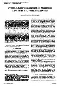
2 Ring networks A ring is a collection of point-to-point links that connect N nodes in a loop as shown in figure 1. The links can be unidirectional or bidirectional. Routing in a ring is very simple: a packet is forwarded from one node to the next until it reaches its destination. In the case of bidirectional rings, at injection time the packet is sent in the direction of its minimal path. From node
To node
(a) In
Out Arbiter
(b)
(c)
Fig. 1. Ring topology for N = 5 with (a) unidirectional and (b) bidirectional links. (c) ring node for unidirectional ring.
We can view a bidirectional ring as a set of two unidirectional rings. Thus, we will first study the simplest unidirectional ring. Figure 1(c) shows the router node for such a network. A ring router has a very simple architecture: it accepts messages from both its neighbour node (or nodes if bidirectional) and its local injection interface and
according to their destination the routing logic selects whether to forward or deliver it. The crossbar switch connects the input and injection buffers to the output and delivery buffers. Finally, the link controller implements VCT flow control. As the ring topology contains a cycle, it is possible for this network to reach deadlock when all its nodes have full input and output buffers and none of their messages have reached their destinations yet. No message can be forwarded; all of them are waiting for a packet buffer to become empty. Network deadlock can be prevented by using virtual channels to break this cyclic dependency. This method, initially proposed for wormhole torus networks[4], has been widely used in multicomputer systems such as the Cray T3D [11]. Deadlock can also be avoided if each node is prevented from filling its local buffers as described in [10]. This means that packets at the injection queue must satisfy more restrictive flow control conditions than VCT (the existence of two free packet buffers instead of one). A switching technique based on this mechanism has recently been implemented in the BlueGene/L supercomputer [1]. In this paper we present results using the latter although similar responses were observed with the former method. 2.2 Performance: theoretical limits The goal of a good design is to achieve high throughput, close to 100% link utilization at high loads, while providing fast switching at low loads. Maximum throughput under random uniform traffic is limited by the network bisection bandwidth - the minimum number of channels that must be removed to partition the network into two equal sub-networks [5]. In a unidirectional ring of N nodes, the maximum injection rate is 4/N flits/cycle/node. Real networks, though, exhibit peak throughputs in the range 70 to 90% of this theoretical limit. If we know the causes behind the 10 to 30% performance loss, we may be able to push network performance closer to its limit. In fact, in a unidirectional ring under heavy loads there are only two scenarios in which the link is not utilized: 1) When there are no packets to forward: the incoming packets are being delivered and the router has no blocked packets for that direction. 2) When the flow control stop us from sending because the next router buffer is full The first scenario is not intuitive, as a congested network will have overflowing injection queues. However, a large network has a small node injection rate with variable arrival rates, so it is possible that while the router is delivering one packet it has no new packets to keep the output link busy. This effect was identified and quantified by Pertel [14] and amounts for a small percentage, which is a function of the network size N; for a small N, such as 8, the maximum link utilization is 85% but for a large N such as 128, the value obtained (98.4%) is close to full utilization. In any case, this effect does not depend on the router design. The second scenario can be prevented by managing the buffer space so that it not likely to be full. In other words, buffer resources should be allocated in such a way that they provide enough packets to keep the link busy most of the time as well as reducing the likelyhood of becoming full. Transit packets release one buffer at the leaving node, while occupying another at the receiving node (in our router, a packet
buffer is available to receive the next packet as soon as the packet header leaves). Therefore, our buffer management will focus on restricting access to new messages, so that buffers are not overflowed. There is a small body of research on restrictive injection in low degree networks. Stamatopoulos[12] proposes a congestion control mechanism which uses control packets to implement barriers in a cut-through 2D mesh. Lopez [7] restricts message injection in a wormhole torus network in order to reduce the probability of deadlock. Dally and Aoki [3] throttle injection in a wormhole mesh by limiting the number of virtual channels a new packet can request. All of them show that holding back packets at congested loads is a successful strategy regardless of flow control. Therefore, we want to understand why and how limited injection works under VCT.
3. Evaluation of ring injection policies In order to evaluate buffer management policies in a ring network, we have used a cycle driven simulator which models the basic router node described in section 2.1. To simplify the model and eliminate trailing effects the packet size is set to 1 phit. Simulations with larger message size exhibit similar trends so they won’t be shown. Our injection policy will be based on local buffer occupation. We have set the buffer size to 8 packets per physical link We will vary the free local buffer space required to inject a packet from the minimum, 2, to 7. The ring size varies from 16 to 128 nodes. The traffic pattern is random or uniform traffic: each node sends messages to any other node with equal probability. We should note that in a 1D ring, head-of-line blocking only occurs when a packet at the input FIFO, which is to be delivered, prevents another packet to move to the output queue. As the processor node is model as an ideal sink, this will never occur for the unidirectional ring. As the goal is to increase link utilization, we will examine network performance versus offered load. We will measure the average network population and its impact on peak throughput at and beyond saturation. We will not show values for network latency as it does not provide any further insight. 3.1 Applying Restrictive injection to unidirectional rings Figures 2 shows the throughput as a function of the offered load achieved with and without additional restrictive injection. The acronym R64-f4 means a simulated ring of 64 nodes allowing packet injection into an output channel when it has space for four packets. Note the minimum under bubble routing is two packets (f=2). Looking at network response for that base case, its peak throughput ranges from 80% for the 16-node ring to 90% for the 128-node ring.
100.00
R32-f2 R32-f4 R32-f7 R64-f2
Throughput
90.00
R64-f4 R64-f7 R128-f2 R128-f4
80.00
R128-f7
70.00 70%
80%
90%
100%
Offered Load
Fig. 2. Throughput versus offered load for unidirectional rings of variable size under increasingly restrictive injection policies. Table 1. Ring population and buffers occupation at peak and full network loads Ring size Peak Throughput Net pop % occupied Throughput (100% Load)
16
32
64
128
80 %
85 %
89 %
90 %
48
91
198
367
0.38
0.35
0.39
0.36
79 %
79 %
78 %
78 %
Net pop
109
223
455
918
% occupied
0.85
0.87
0.89
0.90
However, with 100% offered load throughput degrades down to 78%. To explain this loss we refer to buffer occupation at and beyond saturation as shown in Table 1. We can see that rings saturate with loads that use approximately 35% of buffers regardless of network size. In all cases, ring population soars beyond saturation. Note that the deadlock avoidance method prevents new packets from filling the last free buffer, thus the packets queuing at the node interface will access 7 of the 8 local buffers (87% buffer capacity). This reduces the mobility of transit packets – compare buffer occupations at peak and full loads - and results in 10% throughput loss. These results indicate the need for an injection policy that reserves additional buffer space for packets already in transit. Figure 3 shows the impact of restrictive injection policies on maximum sustained throughput.. For any node size, reserving an additional free buffer result in a significant performance gain. On the other hand, reserving 7 buffers reduces peak throughput down by 5% by preventing too many packets from entering the ring so that the link is slightly under-utilized. Note that in this network all packets in transit request the same output link, so a low population of one to two packets per link is enough to keep the link fully utilized.
100.00
95.00
Throughput
90.00
85.00
16-node 80.00
32-node 64-node
75.00
128-node 70.00 2
3
4
5
6
7
Number of requested free buffers for injection
Fig. 3. Maximum sustained throughput as a function of the injection policy for rings of size 16 to 128 nodes.
We should note that holding packets back does not only eliminates the 10% performance drop but it results in higher peak throughput as well. For example, a 128node ring is saturated at 95% load, delivering only 80% as shown in figure 2. However, if we hold some packets back at the node interface, the network does not saturate. Besides, at full load is able to deliver not only 95% but up 98.4% of packets. The network behaviour as seen by the network interface when reserving 3 to 6 free packets for transit traffic is remarkable similar in terms of throughput and latency. For example at 90% load, average latency is either 206 or 207 cycles for any of the above policies. With R128-f3, the packet will spent on average 4 cycles waiting at the injection frame and 202 traveling towards it destination. With R128-f6 it will wait longer, 27 cycles, but it will travel faster as well, 180 cycles. There is also a clear difference in buffer occupation, ranging from 70% for R128-f3 to 35% for R128-f6. Note the latter figure matches the occupation at peak loads. So, we are not reducing the number of packet required to keep the links busy in spite of the restrictive conditions. Furthermore, the network delivers more packets if is kept nearly empty than if is allowed to flood all but one packet.
3.2 Applying Restrictive injection to bidirectional rings This section evaluates the performance of bidirectional rings. We have provided two injection queues, one per direction, so the main difference with the previous network is that messages travel shorter paths. Besides, they share access to the delivery channel. Thus, is not surprising that the network behaviour is similar to that observed for its unidirectional counterpart (refer to fig 2). Figure 4 shows the network performance as a function of offered load for three bidirectional rings of size 32, 64 and 128 nodes. As the ring size grows, so it is does its peak throughput. However, for loads above saturation, throughput performance degrades back to 70%, a drop of up to 20%.
Throughput versus offered load 100.00
Throughput
90.00
R32-f2
R32-f4
R32-f7
R64-f2
R64-f4
R64-f7
R128-f2
R128-f4
R128-f7 80.00
70.00
60.00 60%
70%
80%
90%
100%
110%
Offered Load
Sustained Throughput as a function of requested free buffers 100.00
95.00
Throughput
90.00
85.00
80.00
16-node
75.00
32-node 64-node
70.00
128-node 65.00 2
3
4
5
6
7
Number of free buffers for injection
Fig. 4. Throughput for bidirectional rings under increasingly restrictive injection policies.
Again, requesting more free buffers before entering the network not only eliminates the drop but it also achieves slightly higher throughput. As Figure 4 shows, the networks works better if is prevented from filling up its buffers. Note that in all cases is better to be too restrictive (f=7) than too generous (f=2). Thus, a safe bet for any network size will be to reserve half of the buffer capacity to transit packets. We can conclude that any given ring has an optimal population that allows the network to deliver maximum throughput. The population should be large enough to use all the network links, cycle per cycle, but small enough so that it maintains free space at each input buffer. For the network under study, a population of 2 to 3 packets per node is sufficient to keep the links busy. The remainder buffer is used more effectively when reserved for transit traffic.
4. Conclusions In this paper we have explored injection policies that limit packet population in the network as a strategy to increase and sustain network peak throughput. We have seen that buffers are a critical resource in a virtual cut-through network. To utilize a network link we require a packet in the sending node and a free buffer in the receiving node. At heavy loads, buffer allocation should restrict new packets from accessing the scarce free buffers, which are compulsory to drain the network.
This work presents the first study of the impact that packet population has on peak throughput. Our simulations show that a ring work best when reserving at least 3 packet buffers to hold transit packets while the remaining buffers are used sporadically to cope with temporary congestions. The understanding gained from simple 1D rings will allows us to develop better buffer management policies for cut-through networks such as 2D and 3D torus currently used to built parallel systems. Acknowledgments This work has been supported by the Spanish CICYT TIC2001-0591-C02-01
References 1. NR Adiga, GS Almasi, et al., “An Overview of the BlueGene/L Supercomputer”, Proc. of SuperComputing 2002, Baltimore, Nov. 16-22, 2002 2. B.W. Arden and H. Lee, “Analysis of Chordal Ring Networks”. IEEE Transactions on Computers, vol 30 no. 4 pp. 291-295. April 1981 3. W. J. Dally, H. Aoki, “Deadlock-Free Adaptive Routing in Multicomputer Networks Using Virtual Channels”. IEEE Transactions on Parallel and Distributed Systems vol 4 no. 4 pp. 466-475. April 1993 4. W.J. Dally, C.L. Seitz, “The Torus Routing Chip” Distributed Computing vol 1 pp. 187-196. 1987 5. J. Duato, S. Yalamanchili and L. Ni, “Interconnection Networks: an engineering Approach”, IEEE Computer Society Press, 1997 6. M. J. Karol, M. G. Hluchyj, S. P. Morgan, Input Versus Output Queuing on Space Division Packet Switch, IEEE Transactions On Communications, vol 35 no. 12, pp.1347-1356. 7. P. López, J. M. Martínez, J. Duato, and F. Petrini, “On the Reduction of Deadlock Frequency by Limiting Message Injection in Wormhole Networks. PCRCW Lecture Notes in Computer Science 1417: pp. 295-307, 1997 8. R. Sivaram, C.B. Stunkel, and D.K. Panda, “HIPQS: a High-Performance Switch Architecture Using Input Queuing”, Proc. IPPS/SPDP’98, March 1998. 9. M. Katevenis, P. Vatsolaki, and A. Efthymiou, “Pipelined Memory Shared Buffer for VLSI Switches”, ACM SIGCOMM, August 1995. 10. V. Puente, C. Izu, J.A. Gregorio, R. Beivide, and F. Vallejo, “The Adaptive Bubble Router”, J. of Parallel and Distributed Computing. vol 61, no. 9, pp. 1180-1208.September 2001 11. S. L. Scott and G. Thorson, “The Cray T3E networks: adaptive routing in a high performance 3D torus”, Proc. of Hot Interconnects IV. 1996 12. J. Stamatopoulos and J. A. Solworth, “Universal Congestion Control for Meshes”. 7th Annual ACM Symposium on Parallel Algorithms and Architectures. SPAA '95 (165-174) ACM Press 1995 13. Y. Tamir, and G.L. Frazier (1992), Dynamically-allocated Multiqueue buffers for VLSI Communication Switches, IEEE Trans. on Computers, vol 41 no. 2 pp. 725-737. 1992 14.. M. J. Pertel, “A Critique of Adaptive Routing” Technical Report Caltech-CS-TR-92-06. 199