Jan 31, 1992 - cess to and transfer of scientific and technical information for DoD ..... (perhaps as specified by a standard such as DoD-STD 2167A) can be.
Technical Report CMU/SEI-91-TR-31 ESD-TR-91-31
Understanding Integration in a Software Development Environment Alan W. Brown Peter H. Feiler Kurt C. Wallnau January 1992
Technical Report CMU/SEI-91-TR-31 ESD-TR-91-31 January 1992
Understanding Integration in a Software Development Environment
Alan W. Brown Peter H. Feiler Kurt C. Wallnau Software Development Environments Project
Unlimited distribution subject to the copyright.
Software Engineering Institute Carnegie Mellon University Pittsburgh, Pennsylvania 15213
This report was prepared for the SEI Joint Program Office HQ ESC/AXS 5 Eglin Street Hanscom AFB, MA 01731-2116 The ideas and findings in this report should not be construed as an official DoD position. It is published in the interest of scientific and technical information exchange.
FOR THE COMMANDER (signature on file) Thomas R. Miller, Lt Col, USAF SEI Joint Program Office This work is sponsored by the U.S. Department of Defense. Copyright © 1991 by Carnegie Mellon University. Permission to reproduce this document and to prepare derivative works from this document for internal use is granted, provided the copyright and “No Warranty” statements are included with all reproductions and derivative works. Requests for permission to reproduce this document or to prepare derivative works of this document for external and commercial use should be addressed to the SEI Licensing Agent. NO WARRANTY THIS CARNEGIE MELLON UNIVERSITY AND SOFTWARE ENGINEERING INSTITUTE MATERIAL IS FURNISHED ON AN “AS-IS” BASIS. CARNEGIE MELLON UNIVERSITY MAKES NO WARRANTIES OF ANY KIND, EITHER EXPRESSED OR IMPLIED, AS TO ANY MATTER INCLUDING, BUT NOT LIMITED TO, WARRANTY OF FITNESS FOR PURPOSE OR MERCHANTIBILITY, EXCLUSIVITY, OR RESULTS OBTAINED FROM USE OF THE MATERIAL. CARNEGIE MELLON UNIVERSITY DOES NOT MAKE ANY WARRANTY OF ANY KIND WITH RESPECT TO FREEDOM FROM PATENT, TRADEMARK, OR COPYRIGHT INFRINGEMENT. This work was created in the performance of Federal Government Contract Number F19628-95-C-0003 with Carnegie Mellon University for the operation of the Software Engineering Institute, a federally funded research and development center. The Government of the United States has a royalty-free government-purpose license to use, duplicate, or disclose the work, in whole or in part and in any manner, and to have or permit others to do so, for government purposes pursuant to the copyright license under the clause at 52.227-7013. This document is available through Research Access, Inc., 800 Vinial Street, Pittsburgh, PA 15212. Phone: 1-800-685-6510. FAX: (412) 321-2994. RAI also maintains a World Wide Web home page. The URL is http://www.rai.com Copies of this document are available through the National Technical Information Service (NTIS). For information on ordering, please contact NTIS directly: National Technical Information Service, U.S. Department of Commerce, Springfield, VA 22161. Phone: (703) 487-4600. This document is also available through the Defense Technical Information Center (DTIC). DTIC provides access to and transfer of scientific and technical information for DoD personnel, DoD contractors and potential contractors, and other U.S. Government agency personnel and their contractors. To obtain a copy, please contact DTIC directly: Defense Technical Information Center, Attn: FDRA, Cameron Station, Alexandria, VA 223046145. Phone: (703) 274-7633. Use of any trademarks in this report is not intended in any way to infringe on the rights of the trademark holder.
Table of Contents 1
Introduction
1
2
Integration in a SDE 2.1 IPSE Integration 2.1.1 IPSE Mechanisms 2.1.2 IPSE End-user Services 2.1.3 IPSE Process Support 2.1.4 IPSE Summary 2.2 CASE Integration 2.2.1 CASE Mechanisms 2.2.2 CASE End-User Services 2.2.3 CASE Process Integration 2.2.4 CASE Summary
3 3 3 4 5 5 6 7 7 9 10
3
Integration of Configuration Management in an SDE 3.1 A Conceptual Architecture for Configuration Management Support 3.2 Integration of IPSE with CM 3.2.1 Mechanism Integration 3.2.2 End-User Services Integration 3.2.3 Process Integration 3.3 Integration of CASE with CM 3.3.1 Mechanism Integration 3.3.2 End-User Services Integration 3.3.3 Process Integration 3.3.4 Scaling-up to a Multi-CM, Multi-CASE Integration 3.3.5 Summary of CASE/CM Integration with State-of-Practice Techniques
13 14 15 16 16 17 17 17 19 20 21 22
4
Summary and Conclusions
References
CMU/SEI-91-TR-31
23 25
i
ii
CMU/SEI-91-TR-31
List of Figures Figure 3-1 Figure 3-2 Figure 3-3 Figure 3-4 Figure 3-5
CMU/SEI-91-TR-31
A Summary of CASE and IPSE Integration Issues 13 A Conceptual Model for CM Systems 15 Classification of Tool Data Architectures 17 Variation of CM Paradigms Across CASE and CM Tools 19 Comparison of Workspaces and Transactions in SMARTSystem and NSE 19
iii
iv
CMU/SEI-91-TR-31
Understanding Integration in a Software Development Environment Abstract: In the past ten years there has been a great deal of interest in the concept of a Software Development Environment (SDE) as a complete, unifying framework of services supporting most (or all) phases of software development and maintenance. We identify three levels at which the issue of integration in a SDE arises as a key concept — at the mechanism level (interoperability of the hardware and basic software), at the end-user services level (combining the methods and paradigms of the various tools), and at the process level (adapting end-user services to the working practices of different users, projects and organizations). In this paper we examine SDEs from an integration perspective, describing the previous work in this area and analyzing the integration issues that must be addressed in an SDE. For illustrative purposes, a particular focus of the paper is the configuration management aspects of an SDE.
1
Introduction
Developing large-scale software systems is a difficult and complex process involving the control and coordination of many different elements. In producing high-quality products, on time and within predicted costs, software development organizations must typically address:
• technical issues (e.g., “how can I make this work?”); • managerial issues (e.g., “how should my teams be organized?”); • political issues (e.g., “what tools should I buy, from which vendors?”). In many ways, the problems of software development are a direct consequence of the need to manage this combination of human and technical issues. As a result, effective software development environments (SDEs) must provide support for addressing all three kinds of issues. In particular, a key concept within any SDE is integration — bringing together the different SDE components to provide as much support as possible for the various software development tasks. Furthermore, as an SDE is a complex artifact, typically requiring the bringing together of a number of diverse software systems operating on a common platform, we can view an SDE as a systems integration problem. Considering an SDE in this way can lead to an analysis of integration in an SDE at three different levels: 1. At the mechanism level — the interfaces and implementations of SDE services which support tool-SDE hosting and inter-tool cooperation. Mechanisms are frequently partitioned into control, data and presentation mechanisms [16] but can also include mechanisms to support execution (“enaction”) and tailoring of software development process models and other SDE administration CMU/SEI-91-TR-31
1
activities. 2. At the end-user services level — the coordination and cooperation of highlevel clusters of SDE functions which support some end-user activities (e.g., software design, configuration management, software testing). 3. At the process level — adapting and tailoring SDE end-user services to suit the requirements of individuals, projects and organizations, typically by imposing constraints on the way in which the end-user services can be used. In the remainder of this paper, we explore the theme of integration within an SDE by expanding on the above discussion, and analyzing integration in a SDE at these three levels. The paper is organized as follows: Section 2 describes integration in a SDE concentrating on the two main approaches to SDE architecture that can be identified; Section 3 develops these themes further by focusing on the configuration management services provided in a SDE; Section 4 concludes the paper with a review of the main issues.
2
CMU/SEI-91-TR-31
2
Integration in a SDE
In practice, two distinct approaches towards SDE architecture can be distinguished, one based on providing a common infrastructure in which tools can be embedded, the other concentrating on the tools themselves. We refer to the former as the Integrated Project Support Environment (IPSE) approach, as this is the most common term in use. The latter we refer to as the Computer-Aided Software Engineering (CASE) approach, due to the fact that CASE tools are the primary focus of this approach. Both of these approaches address integration in a different way, and hence it is appropriate to examine them separately.
2.1 IPSE Integration The primary reason for the design and implementation of IPSEs was the need to provide better support for the interoperation of collections of tools in the support of software development. Until that point, tools could be developed to interoperate through the use of operating system services (e.g. sharing files, and through the use of remote procedure calls) or by being implemented to interact directly through a common database (e.g. sharing data and data definitions in a common schema, and making use of database security, recovery, and locking mechanisms). Both of these approaches had their uses, but required a great deal of effort on behalf of the tool developers and tool users to ensure that meaningful dialogue was possible between tools. To a large extent, IPSEs have built upon the facilities provided by operating systems and databases in an attempt to harness the best of both of these approaches. The aim has been to make tool writing, tool integration, and tool use as convenient as possible. Their emphasis has been strongly directed towards the generality of IPSE support for different application domains, the scalability of mechanisms provided to handle teams of developers producing large, complex application software, and the breadth of coverage in supporting all phases of the software development life cycle and all possible user roles within that life cycle. There have been a number of important successes of this work, particularly in focusing attention on the importance of an overall environment philosophy, and a well-engineered framework, within which individual tools can operate. In the following sections we examine various approaches to integration in an IPSE, looking at an IPSE from a mechanistic, end-user service and process perspective. In this analysis we highlight some of the shortcomings of the approaches.
2.1.1
IPSE Mechanisms
From a mechanistic perspective, IPSEs have concentrated most of their attention on data integration as the primary means of coordinating tools. As a result, in this brief review we will concentrate our attention exclusively on this area.
CMU/SEI-91-TR-31
3
Typically, a database provides a central repository for all data produced by the tools in the IPSE. Access to the data is via a data schema which records the structure of the data and the interdependencies between data items. Issues concerning the pervasiveness of the database mechanisms (e.g., are tool processes themselves represented in the database?), granularity of data items represented (e.g., is a database item a source file, a program module, or a single line of code?), physical location of data (e.g., is data held locally, at a central site, or duplicated where needed?), and others, are addressed individually by each IPSE. Furthermore, the database mechanisms are often augmented with mechanisms particularly appropriate to software development support. Version control, event or triggering mechanisms, and data abstraction facilities are all typical in this regard [3, 15]. Such facilities can be added to the IPSE by extending the database mechanisms (e.g. the database could be changed to version all data items), or implemented as a layer on top of the database (e.g., a checkin/out facility could be provided to control data input/output). While there are many benefits from using a database-centered approach to IPSE implementation, there are also drawbacks. For example, a shared data model must be defined for all tools using the database if they are to share information, providing agreement on the data structures and data access routines. Not only is the definition of this data model a nontrivial task, but it also produces a large, complex artifact that must now be monitored, controlled and updated as required [13]. The lack of modularity of this model makes the addition of new tools, and the evolution of existing tools, difficult to achieve. Additionally, obtaining an appropriate level of detail at which to define the data schema has led to both over-constrained, and ill-defined models. The former prevents tools from being used in new, innovative ways, while the latter permits inappropriate tool usage.
2.1.2
IPSE End-user Services
The concentration on providing general framework facilities within an IPSE, suitable for many classes of tools, has had two fundamental effects on IPSE work. First, a number of IPSEs have been defined and implemented without there being an available collection of tools that can be used within the IPSE to support the development of a large-scale software system. Second, tool producers have complained that the facilities available in the IPSE do not provide a rich enough set of concepts to ease significantly the task of tool production for an IPSE. Some IPSEs provide little more than can be found in most modern operating systems. In this case, it is the lack of domain knowledge of the IPSE, deliberately excluded from the IPSE to make it more general, that prevents the IPSE from embodying more of the facilities appropriate to particular tools. As a result of the above two effects, and for additional pragmatic reasons (such as the lack of an established IPSE marketplace, instability of many IPSE products, and so on), there has been relatively little work on the end-user requirements for an IPSE and the best ways of satisfying those requirements through integrated collections of end-user services. Where such work has been carried out, it has been in the context of providing generic environment services such as configuration management, document production, and project task control [7]. Many 4
CMU/SEI-91-TR-31
of the approaches implemented have been found to be too generic in the support provided, requiring a great deal of additional work from tool writers or IPSE end-users to customize the services to their needs, while others have been too specific, providing good support for a particular approach to that service, but not for variations on that approach.
2.1.3
IPSE Process Support
To be effective, IPSE end-user services must be adapted to suit different software development processes. There are a number of sources of information that affect this adaptation, including the different user roles to be supported, the characteristics of the product to be produced, characteristics of the development organization and its working practices, and external constraints (e.g. contractual requirements) governing the development of a system. As these aspects can vary enormously from one development organization to another, and from one project to another, two possible approaches to IPSE support are possible: 1. Many IPSEs attempted to remain neutral with regard to their support for many of these aspects, either by providing no direct process support [12], or by providing a very general process encoding mechanism [7]. Their expectation was that this neutrality would broaden the range of organizations and projects for which they could be used. This can be called an “open-IPSE” approach. 2. Some IPSEs decided to concentrate their support on one particular development style, through a fixed set of tools and a predefined data schema [14]. This can be called a “closed-IPSE” approach. As can be expected, both of these approaches had their drawbacks. The closed-IPSE approach raised questions with respect to its flexibility, adaptability, and range of application, while the open-IPSE approach often required complex process descriptions to be encoded before the IPSE could be used. However, it is not clear that we have sufficient knowledge of the software development process to be able to describe specific development processes in the necessary detail, to say nothing of defining a notation capable of describing many different processes that can be used as the basis of an IPSE process-enactment mechanism.
2.1.4
IPSE Summary
In summary, we note that while IPSEs were specifically designed with integration of tools as their primary goal, there have been a number of limitations with the work carried out thus far. This has been seen in:
• An emphasis on integration mechanisms, especially for data integration, at the expense of other concerns and approaches.
• Weak population of supported end-user services with few tools specifically designed to make use of the IPSE mechanisms.
• Difficulties in adapting IPSEs to suit different software development processes, mainly due to the inflexibility of the data model and the weak set of end-user services provided.
CMU/SEI-91-TR-31
5
2.2 CASE Integration The CASE tool market emerged coincidentally to (and in parallel with) large-scale IPSE research and development efforts. We emphasize the term tool market because market forces have had a defining role in establishing the nature of systems integration of CASE tools. Market factors, such as the need to be responsive to customers’ near-term demands and the overall knife’s-edge margin of survival for fledgling CASE tool vendors, resulted in CASE technology characteristics which have substantial impact on CASE integration:
• Due to the relatively limited resources of typical CASE vendors, and the high rate of change in the operating system and workstation marketplaces, vendors must balance the depth and breadth of services provided against the availability of their tools on various popular computer platforms.1 The pressure to maximize product availability across a variety of hardware platforms has produced two tendencies: use of least-common-denominator platform services, and a high degree of tool independence. The leastcommon-denominator tendency reduces dependencies on high-level services (such as object management) that may not be available on a sufficiently large base of installations. A consequence of this is that each tool tends to re-implement critically important services, such as data and configuration management, in ways that are nonstandard across tools, and not accessible by other tools. The isolationist tendency reduces dependencies on the presence of other CASE tools. A consequence of this is that tools tend to become egocentric, i.e., view themselves as the center of all activities during particular stages of the software life cycle.
• CASE tools focus on well-defined sub-domains of an overall software development process, for example design and coding. In fact, vendors are attempting to reach a “local maximum” in which they balance breadth and depth of services offered. As a consequence, no single tool supports the full breadth of software development activities. Similarly, different tools may support different sets of activities, or may support the same sets of activities, but in different ways. This divergence of CASE services makes it difficult to determine which tools, and tool services, can (and should) be combined to provide a consistent set of services with respect to some defined notion of software development process. It is reasonable to differentiate CASE tools from tools in general by the degree to which the tools support software engineering processes. Although this point should not be pushed too far, it does reveal one aspect of CASE tools that has a significant impact on integration — many CASE tools provide in-depth support for highly specialized software development methods (e.g., SASD). Such in-depth methodological support, when combined with a tendency to address a broader range of software development activities, results in a substantial degree of encoding of software process constraints within tools. This has impact on process-level adaptability of individual tools, and collections of tools. We elaborate on each of these characteristics in the following sections.
1
6
In contrast, most IPSE developments have been carried out by large, multinational companies, or collaborations of companies, or else they have been sponsored by government research and development programs. CMU/SEI-91-TR-31
2.2.1
CASE Mechanisms
While IPSE mechanisms constitute a kind of standard, or “open system” definition of services for use by integrated tools, no such corresponding notion of openness has developed in the CASE-tool market. The desirability of direct inter-tool communication has only recently received attention, and thus tool vendors have only recently begun addressing issues of designing open systems. The use of quotes around the term “open system” is meant to communicate the murky semantics of this term. While there is no clear definition of the term, it is clear that individual CASE vendors have their own interpretation. In practice, CASE tool openness can refer to any or all of the following (non-exhaustive) interpretations:
• End-user openness — tools provide some services for user-level customization of the appearance or behavior of the tools. Menu customization is an illustration of end-user openness.
• Schematic openness — tools that publish the location and format of their data. Database schemas and data interchange formats illustrate schematic openness.
• Platform openness — tools executing on a common platform, such as Unix, or with common interaction services, such as are provided with the X-window system.
• Programmatic openness — tools making aspects of their functionality available for use by other tools, frequently through linking libraries. This interpretation is less common. While CASE vendors are increasingly interested in mechanistic aspects of integration, they are hampered from achieving an idealized form of open systems-style mechanism definition. Two factors appear to contribute to the difficulty of evolving to more open, standard CASE mechanisms. The first is vendor isolationism; this has resulted in the development of vendorspecific end-user services that frequently can not be integrated even if integration mechanisms were provided. A second factor is that tools need to be designed to support integration. The absence of this motivating force in early CASE tool design has resulted in tool implementations that would require substantial, expensive modifications to make use of emerging integration mechanisms found in IPSEs such as PCTE [2] and SoftBench [4]. So, while some progress is being made in the development of CASE integration mechanisms, progress is slow, and is usually tightly coupled with CASE vendor business strategies (e.g., development of integration mechanisms to support integration with a selected set of tools provided by vendors in strategic alliances), and is usually coupled to idiosyncrasies of particular tool implementations.
2.2.2
CASE End-User Services
The very richness in number and kind of end-user services provided by the CASE market is itself an obstacle to effective integration. As vendors vied for market shares, they needed to differentiate their tools from their competitor’s. This differentiation took two forms: CMU/SEI-91-TR-31
7
• providing a wider assortment of services (giving customers “more for their money”).
• providing unique services, or common services in a unique way. The former tendency resulted in tools which “spilled over” into other software process niches, e.g., design tools that generate module interface specifications.2 The latter tendency made it difficult to compare tools ostensibly intended to support the same end-user activities. Incomparability of tool services affects not just tool selection, but interacts with the “spillover” phenomenon in that several tools in an environment could provide services supporting the same end-user activities, but support them in different (and possibly unreconcilable) fashions. The difficulty here is where various tools support overlapping end-user activities with different kinds of services, and where these services cannot be delegated by the tools. Multi-user support, configuration management, and data management are typical examples of non-delegable services. As a result, different degrees of incoherence can be introduced by CASE integration, ranging from relatively minor problems such as multiple user-interface interaction paradigms to more serious problems such as data duplication and resultant consistency-management problems. From earlier discussions it should be evident that CASE vendors have focused on providing a wide assortment of end-user services. We have emphasized the term end-user in order to stress the close correspondence CASE services have with specific tasks undertaken by, for example, software developers. This correspondence, too, has impact on CASE services integration. For example, the assertion that some design tool is integrated with some documentation tool itself is meaningless. However, asserting that these tools are integrated because design documentation (perhaps as specified by a standard such as DoD-STD 2167A) can be generated from design diagrams adds substance to the integration claim. This example illustrates that tools are not simply integrated with each other, but are integrated with respect to specific process requirements. Further, entire tools are not integrated, but rather specific tool services (in the example, data flow diagram editing with documentation tool data interchange formats and document templates) are combined with some specific process result (the production of standard documentation) to produce an integration of tool services. While this n-ary relationship between tool services and process elements is conceptually tidy, in practice it is not easy to untangle the process elements from the tool services (again, not surprising since CASE services tend to support end-user activities). That is, CASE services tend to embed process constraints. In cases where the relationship between an end-user activity and process are well-established, such as CASE services to support specific software design activities within a well defined method (e.g., SASD), some embedded process con-
2
8
Some readers may object and say that interface specification is a part — albeit the final part — of the design process. Here we merely distinguish the development of a logical interface as a consequence of a design process from its syntactic representation, which is the logical beginning of a programming process. CMU/SEI-91-TR-31
straints can be benign. In less well-defined activities (from the vantage of established processes) such as programming, embedded processes can add further constraints on the way various CASE services can be combined. As this discussion of CASE end-user services indicates, no single integration solution is likely to be applicable to some arbitrary constellation of CASE tools since the tools provide services which:
• overlap services of other tools, sometimes benignly but frequently in a destructive fashion.
• embed process constraints. • are vendor idiosyncratic, and, as such, are difficult to compare and combine with logically related services provided by other vendors. The conclusion that only “custom” integration solutions are applicable for CASE services integration seems unavoidable, but this conclusion is unsatisfactory nevertheless.
2.2.3
CASE Process Integration
The conclusion that, at present, no fixed engineering solution exists for CASE services integration applies equally to process integration. The previous section discussed the impact and relationship of process requirements with the integration of specific CASE services. In this section, we restrict the focus of CASE process integration to issues of adaptation to an evolving process. There are two aspects of adaptation that need discussion. The first is process adaptation of individual tools, the second is adaptation of integrated services. We address each in turn. There is a wide variety of process adaptation techniques that apply to individual CASE tools. The most common techniques apply some form of tool parameterization. Parameterization can occur at various times, with different implications on adaptability. Examples of parameterization include:
• Installation-time parameterization. This form of parameterization clearly supports only limited adaptability, and effects the entire population of tool users.
• Shared run-time parameterization. For example, the use of tool resource descriptions and search-paths for resource databases (typical in tools making use of the X-Window system, but not exclusively restricted to such tools) allows different groups of users to tailor individual tools for special process requirements. This form of parameterization is clearly more meaningful for process adaptation, since it reduces the cost of adaptation while introducing the concept of scopes of process tailoring and groups of users.
CMU/SEI-91-TR-31
9
• Private run-time parameterization. This form of parameterization is exemplified by the use of tool “flags” which modify the behavior of the tool. This is the most ephemeral form of parameterization, and because of this does not provide useful adaptability support. These parameterization techniques reflect mechanisms for process adaptation, and so might justifiably be considered a part of mechanism integration. Parameterization mechanisms are discussed in the process context precisely because tool vendors tend to use parameterization mechanisms to model both platform constraints and process constraints. This reflects the partial nature of process support within CASE tools. Some elements of process are supported directly by CASE services, while other elements lie in the realm of user expertise and usage conventions. These boundaries are not always well thought out by vendors, so much of the burden of adapting CASE tools to specific process requirements lies in the user’s hands. This leads to a form of adoption that, in practice, constitutes tool-usage conventions, the most significant form of tool process adaptation. For example, naming conventions of tool-generated data and informal communication conventions among tool users can provide (and in practice substantially provide) considerable tool adaptability. There are, however, adverse consequences to both parameterized and user convention adaptation. In the case of tool parameterization, process constraints are explicit, but are embedded (or “encoded”) in tool-specific formats (e.g., resource files, installation scripts, and command aliases). In the case of conventions, the opposite problem arises: the process constraints are all implicit and hence not enforceable, automatable or adaptable in a coherent fashion. Process adaptation techniques applied to integrated CASE services are more difficult to quantify, partly because of the variation of CASE services, and partly because the integration of services always implies support for specific process activities. Given this, changes to the underlying software processes are liable to require revisiting integration solutions developed for particular CASE services, and potentially redesigning these solutions to accommodate process changes. Given the ad hoc nature of CASE services integration, this form of evolution is likely to be time consuming, expensive and possibly incomplete.3
2.2.4
CASE Summary
In summary, we note that CASE tools are focused on providing support for specific end-user activities, and that this focus, combined with market-induced vendor isolationism, results in CASE technology which is:
• deficient with respect to provision and use of integration mechanisms.
3
Note that we have not addressed another aspect of process evolution: the introduction of newer versions of existing tools. This, too, constitutes process evolution since tools tend to support — and introduce — specific processes.
10
CMU/SEI-91-TR-31
• rich in terms of end-user services, only these services are provided in nonstandard, idiosyncratic fashion.
• difficult to adapt to evolving processes precisely because of the diversity of CASE services and their complex relationship to both external process requirements as well as process elements introduced by the services themselves.
CMU/SEI-91-TR-31
11
12
CMU/SEI-91-TR-31
3
Integration of Configuration Management in an SDE
As illustrated in Figure 3.1, both IPSE and CASE approaches to integration have strengths and weaknesses.
CASE Mechanism
Service
Process
IPSE
Proprietary Least-common denominator Minimal semantics
IPSE framework interfaces Emphasis on data integration
Rich population Non-standard Tool idiosyncratic
Few well-developed end-user services, typically only support horizontal activities (e.g., CM)
Fixed process due to the particular set of tools combined
Either a fixed process in a closed IPSE, or process support mechanisms with no knowledge of a specific process in an open IPSE
Figure 3-1 A Summary of CASE and IPSE Integration Issues
In order to expose these strengths and weaknesses in a more concrete fashion, we now focus on the configuration management (CM) facilities as an important component of any SDE.4 We concentrate on this much narrower aspect of an SDE for a number of reasons:
• The size and complexity of SDEs forces us to focus on a single (or a small number) of well defined sub-areas of SDE technology. Only a few well funded research, academic, or government groups have the resources to address the complete picture.
• CM is an important practical problem in its own right. Many organizations require, and are interested in, CM solutions in isolation and within the context of their wider development environment.
4
For the purposes of this paper we do not define CM explicitly, but consider it only in the general sense of version control, system build control, and so on. For a more detailed description of CM, see for example [bi bibliography] .
CMU/SEI-91-TR-31
13
• Understanding integration of CM within an SDE is a major step in understanding the complete picture. Such an argument is based on the pervasiveness of CM facilities throughout any SDE (version control, access restrictions, build and configuration support, object identification, and so on). In addition, these facilities are typically not provided by a single tool in a SDE, but different aspects are provided in different tools, perhaps duplicated in different tools, and typically without particular regard for consistency and uniformity.
• The choice of CM as a testing ground for our ideas on SDE architectures provides an ideal medium for exploring process integration in an SDE and its relationship to the underlying end-user services and support mechanisms. There are mechanistic issues to CM such as how data objects are recorded, what history information is needed, and how audit trails through system builds are encoded. The underlying mechanisms support higher-level enduser services such as workspaces, system models, transactions, and change sets. Finally, the procedures and policies for using these CM mechanisms and services — who is allowed to change code when, what development standards are used and when are they enforced, how is code released to the field, and so on — are just as important to understanding CM.
3.1 A Conceptual Architecture for Configuration Management Support In order to discuss integration of CM services with tools in an SDE it is first necessary to provide a high-level description of CM services that have been provided by commercial CM tools.5 A more complete exposition of these CM support services can be found in the work of Dart [6] and Feiler [9]. Broadly speaking, CM tools have been introduced to support several classes of CM applications, where a CM application is one of:
• Developer CM — support of individual and (typically) small teams of software developers in their development tasks. Sample CM services for developer CM include team coordination, build and related consistency-maintenance services, and merge services.
• Project CM — support of project management (probably the most familiar). Sample CM services for project CM include problem tracking, change management and release management services.
• Corporate CM — support for corporate level concerns, such as managing multiple product families and software development process improvement. Sample CM services for corporate CM include metrics gathering, and product and customer impact analysis services. As can be seen, CM services do not support a monolithic audience, but instead span widely divergent (and sometimes competing) CM requirements.
5
The distinction between CM system and tool is not significant in the following discussion.
14
CMU/SEI-91-TR-31
In practice, commercial CM systems tend to focus on one (or, at most two) of the above CM application areas, and provide uneven, idiosyncratic support within these application areas. The work by Feiler and Dart is an attempt to provide a conceptual framework for the diversity of commercial CM systems so that the services offered by these CM systems can be described, or related, in a consistent, meaningful way. Dart partitions specific collections of CM tool functions into higher-level concepts; these concepts relate directly to what we have been calling end-user services in this report, i.e., collections of functions to support some end-user service. In her report, Dart describes 15 concepts (called “services” hereafter for consistency), including workspace, object-pool, and repository and system modeling. Feiler identifies four CM paradigms, which he denotes as the checkout/checkin, change set, composition and transaction paradigms. These paradigms can be viewed as higher-level abstractions rather than CM services, in that while CM services are ideally neutral to end-user processes, the CM paradigms are more directly supportive of distinct CM usage models. For example:
• the transaction paradigm supports parallel development within a system. • the composition paradigm supports the construction of product variants from a composition of variant parts.
• the change set model supports the creation of versions through an algebralike application of the sets of differences (or changes) to some base version.
• the checkin/checkout model is a primitive building block which supports the construction of other paradigms. Feiler indicates that these paradigms are not mutually exclusive, and can be combined to achieve, or support, different end-user processes. Putting these elements together, we get a three-level conceptual architecture for CM which, not coincidentally, resembles the three levels of integration used throughout this report. This CM architecture is depicted in Figure 3-2. At the mechanisms level are specific CM tools (and systems). The services level reflects, at one level of abstraction, services (“concepts”) specific to the CM domain, and, at a higher level of abstraction, CM paradigms which constitute virtual machines for carrying out CM processes. At the process level are CM-specific processes which are supported by CM services, such as change control processes.
3.2 Integration of IPSE with CM Some aspects of CM are supported in most IPSEs. We examine some of these issues with regard to integration of tools with these CM facilities within an IPSE.
CMU/SEI-91-TR-31
15
CM Processes
CM Paradigms
process
end-user services
CM Services
CM Tools
mechanisms
Figure 3-2 A Conceptual Model for CM Systems
3.2.1
Mechanism Integration
As a fundamental service to tools, all IPSEs provide some level of mechanistic support for CM. To a large degree, however, this support is rudimentary, typically designed in an ad hoc fashion based on the IPSE designers’ judgement of what CM mechanisms IPSE tools are likely to require. As there is little consensus amongst tools regarding CM, IPSE designers often resorted to a least common denominator approach. Hence, as all tools require some form of version management for the data produced/used, many IPSEs provided support for version control within (or on top of) the data storage mechanisms and little else. No knowledge of the semantics of the data objects is available at this level. This has the advantage that all data can be versioned using the same mechanism, regardless of its type. However, it also has the disadvantage that no understanding of the insert, delete and update semantics of different kinds of data object can be included in the mechanisms.
3.2.2
End-User Services Integration
In IPSE frameworks such as PCTE [2] and Aspect [3], no further assistance is provided for CM other than the basic mechanisms. It is now the task of the IPSE customizer to implement CM end-user services from the basic mechanisms. This can be a complex, and difficult process. In both PCTE and Aspect, developing CM end-user services would require substantial additions to be made to the data schema of the IPSE and the operators defined for accessing the new schema structures.
16
CMU/SEI-91-TR-31
Once implemented, the CM services can be used by IPSE tools by accessing the data structures described in the data schema that use the basic data manipulation operators of the IPSE, or by executing the new operators defined to manipulate that data.
3.2.3
Process Integration
Populated IPSEs such as ISTAR [7] and PACT [15] provide a set of CM end-user services. In the case of ISTAR (and others), the services that have been implemented presuppose a particular usage pattern, and are not readily adaptable to new usage patterns. For example, in ISTAR the notion of a contract is central, representing a work package that is to be monitored and controlled. In theory, a contract is a very simple notion that can be employed in many ways to support different software development processes. In practice, however, implementation of CM end-user services restrict the use of contracts to a small number of ways. For instance, it was expected that each contract would be operated on by a single person. As a result, each contract has its own database, with no facilities for simultaneous access to a database by more than one user. Similarly, there were no mechanisms provided for easily transferring data from one contract to another during the course of executing a contract, as it was never anticipated that this would be required [10].
3.3 Integration of CASE with CM Given the ad hoc nature of CASE integration with currently available integration technology, it is difficult to provide meaningful, concrete examples of specific CASE integration solutions without having to delve into too much detail on the particulars of specific tools. Instead, our strategy is to highlight paradigmatic mechanisms, services and process integration issues that are likely to arise.
3.3.1
Mechanism Integration
Rather than attempt a classification of different kinds of service interface mechanisms, we illustrate mechanism integration issues related to CASE architectures — a larger-grained (but equally important) view of CASE mechanisms to lower-level interfaces. These issues are representative but by no means exhaustive. Figure 3-3 illustrates a partitioning scheme for CASE architectures, and indicates CM integration issues that arise solely from these architecture-level distinctions. These issues are summarized, as follows:
• Deriver and filter tools are essentially stateless, single-user systems,6 so that the key issue of integrating such tools with CM lies in describing and maintaining the consistency relations between source objects and derived objects. These issues are well understood (e.g., the Unix Make program).
6
The distinction between deriver and filter tools is not critical for this discussion.
CMU/SEI-91-TR-31
17
Deriver/ Filter Tool
Data Dictionary Tool data dictionary
source data derived data
Database Tool database
Figure 3-3 Classification of Tool Data Architectures
• Data dictionary tools are more commonplace in the CASE tool arena, and they differ from deriver tools in that the derived data is placed under some form of data management regime by the CASE tool. Frequently, this data management regime is opaque to users (and tools), so that access to derived data is possible only through access services (e.g., editing services). The key issues of data dictionary tool integration with CM lies in maintaining the consistency of source objects extant in an external environment, and derived data private to the data dictionary tool. Where the tool provides obvious operations for maintaining this consistency (e.g., an Ada compiler provides a compile service for updating the program library — which is a data dictionary) this is not a problem. However, if consistency can only be reestablished by actions taken by developers at the user interface of the CASE tool, then data dictionary consistency can become difficult. A related issue concerns the cost of reestablishing consistency of data dictionaries. If the data dictionary can not itself be versioned, then the source associated with specific versions of the dictionary will need to be completely reprocessed to re-derive the entire dictionary. This is potentially a very costly operation.
• Database tools are similar to data dictionary tools, except that both source and derived data are under the tool’s control. Since the source is under the tool control, it has better opportunities for keeping derived data consistent without the need for manual intervention. However, a drawback is that this approach creates duplicate copies of the source — both within the tool, and within the enclosing environment. Should changes to source information in the environment occur, a different, more difficult kind of consistency management problem will be encountered (i.e., merge). 18
CMU/SEI-91-TR-31
As can be seen, tool architectures can have significant impact on the mechanistic aspects of CASE/CM integration. An additional complication arises if we also consider how specific CASE architectures may interact with the architecture of a CM system. For example, clientserver tools may interact with CM systems that provide configuration context information on a per-process basis, i.e., where client and server processes will have different “views” of the CM repository. For example, both the Sun Network Software Environment [5] and HP/Apollo’s Domain Software Engineering Environment [11] have CM systems which make use of per-process context information.
3.3.2
End-User Services Integration
Some of the variation of related services provided in CASE and CM tools is illustrated through a representative sampling of CASE and CM tools depicted in Figure 3-4.
System
CM Paradigm
Unix RCS
checkout/checkin (co/ci)
SMDS Aide De Camp
change set & co/ci
SoftTool CCC
transaction & co/ci
Sun NSE
transaction
Apollo DSEE
composition & co/ci
ProCASE SMARTSystem
transaction
IDE Software through Pictures
co/ci
Rational Environment
transaction & composition
Figure 3-4 Variation of CM Paradigms Across CASE and CM Tools
This sampling shows how different tools and CM systems provide different sets of services, and that the services are often combined. Thus, for example, while the Sun Network Software Environment (NSE) [5] supports primarily the transaction paradigm, the Rational environment [8] combines elements of both the transaction and composition paradigm. However, the Rational transactions are more constrained than their counterparts in NSE.
CMU/SEI-91-TR-31
19
workspace
transaction
NSE
SMARTSystem
arbitrary nesting
1-level transaction
optimistic concurrency
pessimistic concurrency
checkpointing
no checkpointing
multiple users
single user
local history
no local history
manages multiple configurations
manages single configuration with single executable
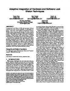
Figure 3-5 Comparison of Workspaces and Transactions in SMARTSystem and NSE This kind of variation of semantics associated with specific services can be very pronounced. As another example, consider SMARTSystem7 and NSE transaction8 and workspace services. Figure 3-5 illustrates how in these two systems transaction and workspace services support nearly diametrically opposing semantics.
3.3.3
Process Integration
Services provided by individual tools and CM systems will often impose their own process constraints that may be difficult to work around. For example, pure transactions imply a concept of transaction scopes that may make it difficult to propagate changes across different versions of a system (where versions may be modeled as non-terminated transactions). Such difficulties in adaptability are not indicative of weaknesses in particular services, such as transactions, but rather point to the need to provide a wider variety of services which may be used more appropriately under different process contexts. The available variety of services available in the CASE market is perhaps its greatest asset. On the other hand, as indicated earlier in this paper, the integration of specific services in CASE tools implies support for specific process elements. We can illustrate this point more clearly through use of a concrete example with CASE/CM integration. Consider the integration of SMARTSystem and NSE (from Figures 3-4 and 3-5). There are a number of possible ways
7
A “C” programming tool marketed by ProCASE.
8
Transaction services should not be confused with the transaction paradigm of CM, which may imply the use of additional services and usage conventions.
20
CMU/SEI-91-TR-31
of integrating services from these system — each of which implies support for specific process activities, imposes some constraints on these activities, and provides some manner for tailoring the integration solution (through usage conventions, for example) to support different processes. For example, one possible integration of services would be to integrate SMARTSystem workspaces with NSE transactions in such a way that workspaces would be associated in a 1:1 fashion with specific transactions. The advantages of this form of integration would be to augment SMARTSystem’s “flat” notion of transactions with NSE’s richer, scoped (nested) transactions. Conversely, NSE’s optimistic concurrency control and build services would be enhanced9 by the use of SMARTSystem’s fine-grained object locking and more sophisticated software build optimizations. The process implications of this integration is that a fresh SMARTSystem database needs to be created for each NSE transaction in which software changes will occur. At the level of process conventions, we might insist that where NSE transactions have associated SMARTSystem workspaces, no changes to source can occur except within SMARTSystem transactions; this convention would greatly simplify (though not eliminate) difficulties in maintaining consistency between overlapping services such as the maintenance of system build relationships (which are being managed by both NSE and SMARTSystem).
3.3.4
Scaling-up to a Multi-CM, Multi-CASE Integration
These CASE/CM illustrations were focused primarily on achieving satisfactory pair-wise integration of tools. It is clear that in practice CASE/CM interactions are going to involve many tools interacting with a CM system. There are inter-tool coordination issues that arise in order to achieve effective cooperation among several tools through some shared set of CM services. For example, several tools might need to agree upon locking conventions where data is duplicated across several private tool repositories. The effective integration of a tool’s services with those of a CM system may require the active participation of several tools. For example, consistency maintenance may require the execution of services residing in many different tools to support the automatic propagation of changes through a shared repository into local tool repositories (in the case of CASE tools with data dictionary and database architectures). The above example describes how in practice the relationships between CASE and CM will be many-to-one (i.e., many tools and one CM system). However, there is no reason to constrain this relationship in this way. In fact, if we consider that some primitive CM services will reside in many CASE tools, and that in many cases these services will be non-delegable, then in practice, we would not be far from admitting a more general many-to-many interaction of
9
It is possible that some readers would object to the idea that fine-grained locking is an enhancement over optimistic concurrency schemes.
CMU/SEI-91-TR-31
21
CASE tools and CM tools. For example, a tool may be integrated over time with several distinct CM tools, each providing complementary services (for example, developer services such as team coordination versus problem tracking services). It is also reasonable to consider several such tool/CM integrations existing simultaneously—indeed, this seems to follow from the observation that any CASE integration scenario will include tools which share CM responsibilities.
3.3.5
Summary of CASE/CM Integration with State-of-Practice Techniques
The rich variety of end-user services available in the CASE market provide considerable flexibility in crafting an integrated environment to support a wide range of processes. However, the idea that integration solutions require crafting is unsettling, since it implies the creation of integration solutions which may suffer from problematic maintenance under evolution of process requirements, new tools and new versions of old tools. Difficulties in evolving CASE integration solutions is partly due to the instability of CASE integration mechanisms, but is more substantially due to the use of either implicit process constraints (i.e., conventions) or embedded process constraints (i.e., software written to integrate particular CASE services).
22
CMU/SEI-91-TR-31
4
Summary and Conclusions
Examining current approaches towards the design of software development environments from a systems integration perspective has provided a number of insights into the present state of this work. In particular, it has allowed us to focus on three distinct aspects of integration:
• Integration of mechanisms and infrastructure services as the basis of a SDE. • Integration of the concepts and services available to the SDE end-user. • Integration of a SDE with the development process of an organization. By distinguishing these three aspects, a number of limitations with both IPSE and CASE environments have been highlighted, based on our characterization of their approaches toward integration. In this paper we have examined these integration issues in a general context, and with respect to configuration management support in particular. Furthermore, identification of the three aspects of integration leads us to consider ways of providing a more flexible approach to integration in a SDE, capable of directly supporting them. As a result, a current focus of our work is the development of a “federated” environment architecture in which SDE services are the main component, rather than concentrating on tools, frameworks, and so on. The key characteristic of the architecture is a separation of implementation mechanisms from services, with process and policy issues addressed as constraints on the application of those services in a particular application domain. By taking this approach to SDE architecture, we hope to be able to build on existing SDE technology as a basis, while allowing evolutionary growth and further experimentation with unification of SDE end-user services, and explicit representation of SDE process adaptation. While there is clearly more work required to realize this vision of a “federated” SDE architecture, we believe that by adopting a systems integration perspective, we have gained a deeper understanding of current integration efforts, with the ultimate goal of providing an approach to integration that will ensure better supporting, more adaptable SDEs in the future.
Acknowledgments We are grateful for comments on earlier drafts of this paper from colleagues at the SEI, notably Susan Dart and Ed Morris.
CMU/SEI-91-TR-31
23
24
CMU/SEI-91-TR-31
References [1]
Bersoff, E.H.; & Henderson, V.D.; & Siegel, S.G. Software Configuration Management. Prentice-Hall, 1980.
[2]
Boudier, G.; & Gallo, T.; & Minot, R.; & Thomas, I. An Overview of PCTE and PCTE+. Proceedings of ACM SIGSOFT/SIGPLAN Software Engineering Symposium on Practical Software Engineering Environments, Boston, MA, 1988.
[3]
Brown, A.W. [ed.]. Integrated Project Support Environments: The Aspect Project. The APIC Series. Academic Press Ltd., London, England, 1991.
[4]
Cagan, M.R. “The HP SoftBench Environment: An Architecture for a New Generation of Software Tools.” Hewlett-Packard Journal (June 1990), 36-47.
[5]
Courington, W. The Network Software Environment. Sun Microsystems, Inc., Mountain View, CA., 1989.
[6]
Dart, S. “Concepts in Configuration Management Systems.” Proceedings of the 3rd International Workshop on Software Configuration Management, June 1991, 1-18.
[7]
Dowson, M. “ISTAR — An Integrated Project Support Environment.” Proceedings of 2nd ACM SIGSOFT/SIGPLAN Software Engineering Sympos ium on Practical Software Engineering Environments, December, 1986.
[8]
Feiler, P.; & Dart, S.; & Downey, G. Evaluation of the Rational Environment. Tech. Rept. CMU/SEI-88-TR-15, ADA198934, Software Engineering Institute, Carnegie Mellon University, July, 1988.
[9]
Feiler, P.H. Configuration Management Models in Commercial Environments. Tech. Rept. CMU/SEI-91-TR-7, Software Engineering Institute, Carnegie Mellon University, March, 1991.
[10]
Graham M., & Miller, D. ISTAR Evaluation. Tech. Rept. CMU/SEI-88-TR-3, ADA201345, Software Engineering Institute, Carnegie Mellon University, 1989.
[11]
Leblang, D.; & Chase, R. “Computer-Aided Software Engineering in a Distributed Workstation Environment.” Proceedings of the SIGSOFT/SIGPLAN Software Engineering Symposium on Practical Software Development Environments, Pittsburgh, PA., April, 1984, 104-112.
[12]
Paseman, W. “Tools on a New Level”. Unix Review 7, 6 (June 1989), 69-77.
CMU/SEI-91-TR-31
25
[13]
Penedo, M.H.; & Stuckle E.D. “PMBD — A Project Master Database for Software Enginee ring Environments.” Proceedings of 8th International IEEE Conference on Sof tware Engineering, London, England, August, 1985.
[14]
Strelich, T. “The Software Life Cycle Support Environment (SLCSE): A Computer Based Framework for Developing Software Systems.” Proceedings of the ACM SIGSOFT/SIGPLAN Software Engineering Symposium on Practical Software Development Environments, Boston, MA., November, 1988.
[15]
Thomas, I. “Tool Integration in the PACT Environment.” Proceedings of 11th International IEEE Conference on So ftware Engineering, May, 1989.
[16]
Wasserman, A. Tool Integration in Software Engineering Environments. In F. Long, Ed., Software Engineering Environments, Springer-Verlag1990, 138150.
26
CMU/SEI-91-TR-31
UNLIMITED, UNCLASSIFIED SECURITY CLASSIFICATION OF THIS PAGE
REPORT DOCUMENTATION PAGE 1a. REPORT SECURITY CLASSIFICATION
1b. RESTRICTIVE MARKINGS
Unclassified
None
2a. SECURITY CLASSIFICATION AUTHORITY
3. DISTRIBUTION/AVAILABILITY OF REPORT
N/A
Approved for Public Release Distribution Unlimited
2b. DECLASSIFICATION/DOWNGRADING SCHEDULE
N/A 4. PERFORMING ORGANIZATION REPORT NUMBER(S
5. MONITORING ORGANIZATION REPORT NUMBER(S)
CMU/SEI-91-TR-31
ESD-TR-91-31
6a. NAME OF PERFORMING ORGANIZATION
6b. OFFICE SYMBOL (if applicable)
Software Engineering Institute
SEI
7a. NAME OF MONITORING ORGANIZATION
SEI Joint Program Office
6c. ADDRESS (City, State and ZIP Code)
7b. ADDRESS (City, State and ZIP Code)
Carnegie Mellon University Pittsburgh PA 15213
ESD/AVS Hanscom Air Force Base, MA 01731
8a. NAME OFFUNDING/SPONSORING ORGANIZATION
8b. OFFICE SYMBOL (if applicable)
SEI Joint Program Office
ESD/AVS
9. PROCUREMENT INSTRUMENT IDENTIFICATION NUMBER
F1962890C0003
8c. ADDRESS (City, State and ZIP Code)
10. SOURCE OF FUNDING NOS.
Carnegie Mellon University Pittsburgh PA 15213
PROGRAM ELEMENT NO
PROJECT NO.
63756E
N/A
TASK NO
WORK UNIT NO.
N/A
N/A
11. TITLE (Include Security Classification)
Understanding Integration in a Software Development Environment 12. PERSONAL AUTHOR(S)
Alan W. Brown, Peter H. Feiler, and Kurt C. Wallnau 13a. TYPE OF REPORT
13b. TIME COVERED
14. DATE OF REPORT (Yr., Mo., Day)
15. PAGE COUNT
Final
FROM
January 1992
30
TO
16. SUPPLEMENTARY NOTATION
17. COSATI CODES FIELD
18. SUBJECT TERMS (Continue on reverse of necessary and identify by block number) GROUP
SUB. GR.
CASE integration, process integration, software development environment
19. ABSTRACT (Continue on reverse if necessary and identify by block number)
In the past ten years there has been a great deal of interest in the concept of a Software Development Environment (SDE) as a complete, unifying framework of services supporting most (or all) phases of software development and maintenance. We identify three levels at which the issue of integration in a SDE arises as a key concept — at the mechanism level (interoperability of the hardware and basic software), at the end-user services level (combining the methods and paradigms of the various tools), and at the process level (adapting end-user services to the working practices of different users, projects and organizations). (please turn over) 20. DISTRIBUTION/AVAILABILITY OF ABSTRACT UNCLASSIFIED/UNLIMITED
SAME AS RPT
21. ABSTRACT SECURITY CLASSIFICATION DTIC USERS
Unclassified, Unlimited Distribution
22a. NAME OF RESPONSIBLE INDIVIDUAL
22b. TELEPHONE NUMBER (Include Area Code)
22c. OFFICE SYMBOL
John S. Herman, Capt, USAF
(412) 268-7631
ESD/AVS (SEI)
DD FORM 1473, 83 APR
EDITION of 1 JAN 73 IS OBSOLETE
UNLIMITED, UNCLASSIFIED SECURITY CLASSIFICATION OF THIS
ABSTRACT —continued from page one, block 19
In this paper we examine SDEs from an integration perspective, describing the previous work in this area and analyzing the integration issues that must be addressed in an SDE. For illustrative purposes, a particular focus of the paper is the configuration management aspects of an SDE.