Safe Integration of New Concerns in a Software Architecture: Overview of the Implementation Hanh-Missi Tran∗ , Olivier Barais†, Anne-Fran¸coise Le Meur∗ , and Laurence Duchien∗ INRIA Jacquard Project, LIFL University of Lille I Lille, France {missi, lemeur,duchien}@lifl.fr ∗
†IRISA Triskell Project University of Rennes I Rennes, France
[email protected]
1
Introduction
The construction of component-based systems became increasingly important in software construction. One of the main task in this construction is the specification of the software architecture which consists in defining and combining increasingly complex elements. While these architectures were originally specified informally, recent years have seen the creation of a number of Architecture Description Languages (ADLs) [11], for creating an architecture by constructing and combining increasingly complex elements. There are several advantages to specify the architecture of a software with an ADLs: a better understability of the system structure, a better verifiability with more abstract form of semantic checking and a better reliability thanks to the code generation. Nevertheless, a problem inherently present in the current ADLs and insufficiently addressed by the research community is the high cost of change [7]. Indeed, the consistency of a software architecture is generally checks globally. Each change impacts generally multiple components and connectors. Consequently, the architecture description languages are not adapted to a iterative software development process in which the architect integrates new concerns in a stepwise manner. The recent researches on aspect oriented software development (AOSD) could be a solution of overcoming many of the problems related to software evolution [12]. For managing the evolution of a software architecture by integrating new concerns into a software architecture, we have proposed the TranSAT framework [4]. TranSAT isolates the description of each concern in a separate architecture construct, the pattern, that is automatically integrated into an existing software architecture by a weaver. Analogous to an aspect, a pattern consists of the new architecture fragment to be integrated, a description of where this fragment will be applied, and a specification of the transformations that should be performed to connect this new fragment to the existing architecture. Weaving an aspect/a pattern impacts often several objects/components. Consequently, in lots of existing approaches, the designer has no guarantee that
2
the aspect does not break the program/software architecture consistency. Two different ways are explored to guarantee this consistency: Firstly, the use of Open Modules [1] have be seen as a way to control the access of an advice on a join point. It aims at limiting where an aspect can impact a program. Secondly, the analysis of the transformation aims at guaranteeing that the modifications performed on the program/Software architecture does not have any impact for the software architecture consistency. TranSAT can be classified in the second approach. This paper presents the implementation of the TranSAT framework. Precisely, it investigates the use of a rule engine based on the Rete algorithms [8] to implement the static analyzer, and the logic pointcut language of TranSAT designed at the software architectural level. The rest of this paper is organized as follows. Section 2 gives an overview of the TranSAT framework through an academic example. Section 3 presents the implementation of statics checks performed on the transformation specification to guarantee the consistency of the final software architecture. Section 4 describes the research of join points where a pattern can be applied. Finally, Section 5 concludes this experiment report and presents our future work.
2
Global overview of the TranSAT framework
This section presents an overview of the TranSAT framework through the example of a replicated Web Server software architecture. We first describe the architecture and then show how to use the TranSAT framework to enrich this architecture by adding a new security concern. 2.1
Example
Our example of a replicated Web server performs a round robin algorithms for several Web server called workers. The software architecture is shown in Figure 1(a-b). It is specified using the SafArchie ADL [3]. Like other ADLs, such as Darwin [10] or SOFA [13], SafArchie provides structural and behavioral descriptions of component interfaces. The structural description defines the components and the bindings among them, while the behavioral description specifies the behavioral interactions of each component with its environment. The basis plan, described in Figure 1(a), gives the structural description of the Web Server architecture. The structure is composed of composites (WebServer), components (Coordinator, WorkerX, FileSystem), ports (p1 to p14), delegated ports (dp1) and bindings. Ports contain operations; for example, operations get and post are provided by the ports p5, p6 and p7. A port must contain at least one operation, must be part of exactly one component, and must be bound to exactly one other port, in another component. Operations are either provided or required. Bound ports must contain compatible operations; for example, port p3 requires the operations provided by port p6. Delegated ports do not contain any operations; they define the interface of a composite, exporting the operations of the composite’s components.
3
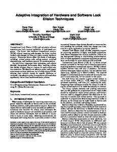
Fig. 1. Overview of TranSAT
Figure 1(b) gives the behavioral description of one of the components, Coordinator. The behavior is specified in terms of an Input/Output Automaton [9] that describes the sequences of messages that a component may receive and emit. The notation used in this automaton is as follows. For a provided operation op1, the message ?op1 represents the receipt of a request and the message !op1$ represents the sending of the response. ?op1 must precede !op1$, but they can be separated by any number of messages, representing the processing of op1. For a required operation op2, the message !op2 represents the sending of a call and the message ?op2$ represents the receipt of the response. Sending a call is a blocking operation, and thus !op2 must always be immediately followed by ?op2$. Using this notation, the behavior shown in Figure 1(b) specifies that when the Coordinator receives a get request, it transfers the request to p3, p4, p5. 2.2
Integrating a security concern using the TranSAT framework
The TranSAT framework manages the integration of a new concern, represented as a software architecture pattern, into an existing architecture, referred to as a basis plan. The software architecture pattern represents the new concern in terms of a plan, a join point mask, and a set of transformation rules. The plan is a fragment of architecture (component, composite, binding) that should be integrated. The join point mask defines the structural and behavioral requirements that the basis plan must satisfy so that the new concern can be integrated. The transformation rules specify the modification to perform to integrate the new
4
plan. For example, in Figure 1, TranSAT introduces a closed language for the specification of the transformation to limit the architect’s errors. The integration process is the following. First, given a join point mask and a basis plan, the framework identifies all the points into the basis plan which are compatible with the join point mask. Next, the architect specifies a pointcut that specializes the join point mask to select the joint points where the new plan has to be added. The TranSAT weaver then instantiates the transformation rules according to the architectural entities matched by the join point mask, and performs the instantiated transformation rules to integrate the new concern into the basis plan. For example, Figure 1 is the result of the integration of the security concern. The two main features of TranSAT are: – the design of a specific language to describe the transformation to perform on a software architecture [6] – the definition of an interface for the aspects of architecture (a pattern), called the join point mask, that define the conditions to use it [2]. The rest of this paper presents how these two features have been implemented in order to provide support for safe integration of new concerns in a software architecture.
3
Correctness of a concern pattern
First, a pattern plan is specified as a component model with the description used in SafArchie. Because the analysis made on a pattern plan are a subset of those performed on a SafArchie component model, the tools implanted for SafArchie are reused to verify its correctness. Then, a join point mask represents a set of architecture elements with which a subset of the basis plan elements has to match up. There is only a syntaxical analysis to be done for this part. At last the set of transformation rules represents the main source of analysis. Indeed, even before applying these rules on the basis plan, static verifications are performed to ensure the correctness of the transformation. 3.1
Transformation language
Transformation rules in the concern pattern are divided into two sets. The first set gathers the rules that modify the structure of an architecture whereas the second set holds the rules that change its interactions. Tables 1 and 2 summarize the transformation rules respectively for each set. The primitives of the transformation language are the followings. An operation can be created or shifted and a port can be created or destroyed. The transformation rules that manipulate operations have repercussions on the behavior of the transformed architecture. These repercussions may be implicit or have to be explicitly specified by the architect. A binding can be created or destroyed, a primitive component can be shifted and a composite component can be created, destroyed or shifted.
5 Port create destroy move
Port Pr in Cp Pr.destroy() N/A
Operation Operation Or = op in Pr Operation Or1 = op replaces Or2 N/A Or.move(Pr )
Cp: ComponentRef; Pr: PortRef; Or: OperationRef; op ::= Or | inverse(Or ) N/A: Not applicable; Table 1. Introduction transformations
Primitive create
N/A
destroy N/A move Cp.move(Cr )
Binding Binding Br ={Pr1 , Pr2 } Br.destroy() N/A
Composite Composite Cr Composite Cr1 in Cr2 Cr.destroy() Cr1 .move(Cr2 )
Cp: ComponentRef; Cr: CompositeRef; Pr: PortRef; Br: BindingRef; N/A: Not applicable; Table 2. Reconfiguration transformations
Several possible rules are not taken into account. For example, the destruction of a primitive component can not occur because it would mean to alter or to remove the functionality associated with this component. Some extra features to the transformation language are needed to perform integration as wished. Firstly, rules that manipulate composite components (by instance, the shifting of a component into a composite component) may need to access to the component model hierarchy. In the case of a join point mask, all the components have implicitly a parent. Indeed the join point mask components are to be matched with basis plan components which have a parent. So, when a transformation rule may refer to a composite component, it can refer directly to a composite component via its name or to the parent of a component. Secondly the operation polarity constitutes the first parameter to be taken into account when verifications are done to test if a binding can be created. In order to let the architect adjust an operation polarity, rules that refer to an operation may specify that this operation is taken into account with an inverse polarity. 3.2
Correctness of the transformation rules
Several verifications are performed on each rule. They can be separated into three fields: – the syntax of the rule; – the type of referred elements of the rule; – the set of constraints associated with the rule and defined to ensure several properties of the transformation. Type of properties to be analyzed and sequence of these verifications A set of transformation rules is checked twice. Firstly verifications control containment properties on the architectural elements (elements of the pattern plan and of the join point mask). According to its nature, an element may have a
6
parent and may own several children. So at the end of the first analysis step, every element must have at least one sub-element except operations and join point mask elements for which no subelements are initially specified. Moreover the only elements that can have no parent are components. If such a component does not belong to the join point mask, it must constitute the only element without parent. Other verifications are performed during this step. They focus on the usefulness and consistency of transformation rules. They allow to prevent an architect from doing unnecessary transformations. For example, it is pointless to move an operation into a port and then to move it into another port. These verifications can also discover errors in the conception of the pattern plan. By instance, if a rule tries to move an operation from a pattern plan, it may mean that this operation was initially misplaced. Secondly similar verifications are performed on rules that deal with bindings. An example of property checked in this step is the compatibility between two ports to be bound, etc. At the end of this step, every port is bound to another one if it was not originally an unbound port of the join point mask. Description of the verifications All the properties checked for a transformation are gathered in an inference. Such an inference is composed of two parts that are separated by a horizontal bar. The upper part specifies hypotheses on the elements referred by the transformation rule. The lower part describes the containment modifications brought by the rule. These modifications are defined in terms of judgements of the form ρ, S1 , ..., Sn ` s → ρ0 , S10 , ..., Sn0 . ρ contains every architectural element and S1 ... Sn are lists of elements manipulated by the analysis. In the case of the containment analysis, two lists are used: the first one to indicate elements of the join point mask and the second one that gathers the elements of the pattern plan whereas in the case of the bindings analysis, two lists are also used but the first one contains bindings and the second one gathers the unbound ports. In the environment ρ, an element is mapped to a couple (π,ζ) where π is its parent and where ζ is the list of its children. The term being analyzed is represented as s. ρ0 , S10 ...Sn0 represent the results of the transformation.
Or ∈ J π 2 = π3 ρ[Or 7→ (π1 , ζ1 ), Pr 7→ (π2 , ζ2 ), π1 7→ (π3 , ζ3 )], J, P ` Or.move(Pr) → ρ[Or 7→ (Pr, ζ1 ), Pr 7→ (π2 , ζ2 ∪ {Or}), π1 7→ (π3 , ζ3 − {Or})], J − {Or}, P Fig. 2. Operation shifting inference: Or.move(Pr )
The static verification of a transformation specification consists in a sequence of verifications.The environment manipulated by each rule is the environment resulting of the simulation of the transformation produced by the previous rule
7
in the rules sequence. The figure 2 displays the inference associated with the operation shifting rule1 . As said earlier, J indicates the list of elements of the join point mask and P gathers the elements of the pattern plan. The hypotheses specify that the parent of Pr which is a component must be also the parent of the port that owns the operation Or. Furthermore the operation Or must be in the list of join point mask elements. The transformation rule removes the operation Or from its parent and adds it to the list of children of the port Pr. Moreover the operation is removed from the list of elements of the join point mask to prevent it from being moved again. 3.3
From the pattern description to the transformation rules analyzer
Figure 3 shows the mechanism to verify statically transformation rules from a pattern plan and a join point mask.
Fig. 3. Mechanism to verify the transformation rules consistency
First, each part of a concern pattern is supported by an XML Schema. So the first analysis consists in a syntaxical verification and rely on the mechanism of validation of an XML document against an XML schema. Then, the pattern plan and the join point mask are merged according to transformations described in XSLT into a common component model on which the initial containment environment will rely. Then objects are generated from the sequence of transformation rules and from the containment architecture through the JAXB unmarshalling mechanism and are given as parameters to the transformation rules analyzer. There are several factors to be taken into account to decide how to implement this analyzer. For each property checked on a rule, it is convenient to have it 1
The semantic of all the transformation operators introduced in Table 1-2 are defined in [5].
8
clearly specified and independent from the others. This separation allows to check it precisely and so, to give more accurate reports when it is not satisfied. Consequently, the use of a rules engine represents a suitable choice. 3.4
Rules engine rule
Drools2 is a rules engine based on a Rete algorithm [8] tailored for Java. Basically a Drools rule is specified by a name and is composed of a non-empty set of parameters, a set of conditions and a consequence. The possibility to use custom strategies for the resolution of conflicts between rules and extra features on rules such as salience values allow to configure how the rules engine work. Each property analyzed on a transformation rule has an associated set of Drools rules. In the case of operation shifting, there are eight main distinct rules: four rules for type checking (does the first referred element exist in the containment environment? Is it an operation? Does the second referred element exist in the containment environment? Is it a port?), two rules for containment verifications (is the operation not already owned by the port? Is the component parent of the port also parent of the port parent of the operation?), one rule for usefulness verification (does the operation belong to the list of elements of the join point mask?) and the last one that did the simulation of the transformation. The rules sets can be written in different ways. Because the transformation rules semantic is defined with a fixed number of judgments, specifications of Drools rules are also made fixed. So the verifications are written as Java classes and the whole is configured by a Spring3 file. Benefits from this approach are the possibility to unit-test rules. Figure 4 shows an excerpt of the definition of the rule set for operation shifting. Elements in the Spring configuration file are declared as beans. So the excerpt describes the rule set for the shifting operation. It contains rules to check if the first referred element of the rule belong to the containment environment, etc.A rule in that case is written as a plain old Java object. To reflect that a Java class is indeed a Drools rule, annotations are added. The figure 5 describes the rule that checks if the operation is not in the join point mask. Annotations indicate that the java class is a Drools rule (annotation @Rule) with the operation shifting rule as its only parameter (annotation @Fact), with three conditions (annotation @Condition) and with a consequence (annotation @Consequence). Containment environment holders are taken into account as application datas (annotation @Data). Static verifications on a concern pattern ensure that its set of transformation rules are consistent with its pattern plan and its join point mask. However that only ensures a local consistency. Dynamic checks need to be performed after the effective transformation of the basis architecture to ensure consistency of the structure and of the behavior of the resulting architecture. The dynamic checks are presented in [6]. 2 3
http://drools.codehaus.org/ http://www.springframework.org/
9 ...
Fig. 4. Rules set definition excerpt
4
Search for integration sites
In the TranSAT process, when an architect has built or chosen a valid concern pattern, he has to decide where to integrate the concern into the basis architecture. Then, the framework helps the architect to find suitable joint points for the pattern. Among the data needed to perform the transformation of the basis plan, the subset of elements of this basis plan which will be manipulated by the transformation rules is a key parameter for this transformation. Such a subset is called a join point. It must correspond to the join point mask defined in the concern pattern. The identification of an integration plan may come either from a search or from a submission. 4.1
Description of a join point mask
A join point mask consists in a description of a set of architectural elements with which a pattern plan is integrated. It relies on structural and behavioral requirements that a join point of a basis plan must fit. Structural elements of a component model are reused in the join point mask but with slight differences. Indeed, they are used as constraints and they are made as loose as possible to allow the join point mask to represent any possible kind of set of architectural elements. For example, the binding in a join point mask does not specify an assembly link (a direct binding) anymore but can be associated with a sequence of delegation and assembly links (an indirect binding). Behavioral constraints are also presented in a join point mask. They allow the addition of a requirement for the component. Currently such a constraint consists in a sequence of messages that must match the behavior of the component.
10 @Rule public class ElementNotInCutMask extends fr.lifl.transformationRules.verification.rules.Rule { @Condition public boolean isElementNotInCutMask( @Fact fr.lifl.transformationRules.jaxb.MoveOperationInTarget transformationRule, @Data(value = "cutMaskElements") HashMap cutMaskElements ) { return cutMaskElements .get(transformationRule.getOperationElement().getValue()) == null; } @Consequence public void consequence( KnowledgeHelper drools, @Data(value = "listErrors") java.util.List listErrors, @Data(value = "transformationRuleStringVersionHolder") StringBuffer transformationRuleStringVersionHolder ) throws FactException { ... } }
Fig. 5. Drools rule as a plain old Java object
Join point mask requirements are gathered in an XML schema. Figure 6 displays an example of a join point mask as an instance of this XML schema. This mask describes an assembly of two components.
Fig. 6. Basic example of a join point mask
4.2
Identification of the compatible join points
The first way to identify a join point is a simple approach. Indeed it lets a search engine find all the integration sites according to a join point mask. However it happens more often that an architect wants the concern to be integrated with
11
specific elements of the basis architecture. If this architect gives only partial pieces of information about the integration site, they will guide the search. But, if he/she completely knows where he wants the concern plan to be integrated and so submits an integration site, the framework checks the conformity between the integration site and the join point mask constraints. Exhaustive search The algorithm to find an element from a basis architecture that match an element from a join point mask works in two steps. Firstly it selects every possible candidate elements by relying only on the structure described by the join point mask and secondly it keeps only those that verify some constraints. Match a component mask For a component mask, match it with a component in the basis architecture if the number of ports of the component mask is lesser than or equals to the number of ports of the component. Then, for each element mask owned by the component mask, match it with an element of the basis architecture. A valid match between a component mask and a basis architecture component follow these conditions: – Each operation sequence of a component must consist in a part of the behavior of the component. – If a message mask references an operation mask, the operations associated with the message mask and with the operation mask must be the same. Match a sequence mask For a sequence mask of a component mask, match it with a sequence of operations owned by the component associated with the component mask. Every couple of an operation mask and a basis architecture operation must respect a constraint between the direction and type of the operation mask and the polarity of the basis architecture operation. Match a port mask For a port mask of a component mask, match it with a port owned by the component associated with the component mask. The number of operation masks must be lesser than or equals to the number of operations of the port. Then for each operation mask owned by the port mask, match it with an operation of the port. A match between a port mask and a basis architecture port is valid if each element of the set of operations relative to the set of operation masks of the port mask must be distinct from the other elements of the set. Match an operation mask For an operation of the mask of a port mask, match it with an operation owned by the port associated with the port mask. The polarities of the basis architecture operation and of the operation mask must be the same. The number of its parameters must be higher than or equals to the number of parameter masks. The return types of the basis architecture operation and of the operation mask must be the same. The n parameters of the operation mask must be identical to the nth first parameters of the basis architecture operation.
12
Match a join point mask A set of basis architecture elements is considered as a join point if: – Each element of the set of components relative to the set of component mask of a join point mask must be distinct from the other elements of the set. – Each element of the set of components relative to the set of component mask of a join point mask must not own another component of the set. – Each couple of ports associated to a couple of port masks that are linked by a binding mask must be linked by a sequence of delegation and assembly links. Guided search A second way to identify compatible join point is the guided search. A set of hints about the integration site is given to the search engine. Such a hint describes an association between two names which represent an element respectively from the join point mask and from the basis architecture. Thus, an additional step occurs before the search. Firstly it checks if each name in a hint and used as a name of an element from the join point mask indicates an existing element from the join point mask firstly and secondly it verifies that the element type of the hint and the type of the existing element correspond. When a hint is taken into account in the search, it adds a further constraint on the match for the element of the join point mask associated with the hint. Thus the more the number of hints is, the faster the search is. Submission of an integration site The last way to identify a compatible join point is the submission of an integration site. The difference with the guided search lies in the join point mask structure that is not necessary present in the set of hints contrary to the integration site. Thus submitting an integration site instead of a complete set of hints leads an architect to respecting more constraints and so, reduces the risks of mismatch. 4.3
Implementation
Each element of the join point mask is roughly associated with a set of rules as previously shown. Thus, search rules have to be generated. As said earlier, Drools rules can be written in different ways. In this case, XML-based rules are used. Thanks to the mask to be specified in XML, transformations from the join point mask and, according to the identification mechanism, from a possible extra element are easily specified via XSLT. Figure 7 shows a Drools rule generated from the join point mask (cf figure 6). This rule catches every integration site by testing every couple of component that was previously found as a match with a component mask. So it takes two components as parameters. The first and second conditions specify that each component mask of the join point mask is matched by a component of the couple. The third condition describes that the first component of the couple has to be distinct from the second one. The fourth and fifth condition states that no
13 fr.lifl.siteIntegration.adaptation.ComponentSiteIntegration fr.lifl.siteIntegration.adaptation.ComponentSiteIntegration componentSiteIntegration1.getComponentMaskName().equals("Cm1")==true componentSiteIntegration2.getComponentMaskName().equals("Cm2")==true componentSiteIntegration1.getComponent().getName(). equals(componentSiteIntegration2.getComponent().getName())==false componentSiteIntegration1.getComponent() .isAncestorOf(componentSiteIntegration2.getComponent())==false componentSiteIntegration2.getComponent() .isAncestorOf(componentSiteIntegration1.getComponent())==false componentSiteIntegration1.getPort("Pm1").getPort() .isBoundTo(componentSiteIntegration2.getPort("Pm2").getPort()) ...
Fig. 7. Example of a generated rule
component of the couple is an ancestor of the other component of the couple. The last rule corresponds to the constraint brought by the binding mask. Each kind of integration site identification is associated with a XSLT document. All these transformation specifications are very close. Indeed, the transformations performed in the guided search and the validation are based on the exhaustive search ones. Conditions based on information about the integration site to be found (element names currently) are generated and are added to the rules that matches the relative mask element. The figure 8 summarizes every possible mechanism of integration site identification. For every kind of identification, the search engine takes the logical architecture transformed into an object via the JAXB unmarshalling mechanism and the Drools rules generated from the join point mask via XSLT as ingoing parameters. If there is no extra information for integration sites search, it corresponds to an exhaustive search. Rules are generated only from the join point mask. If there are hints to specify some parts of the integration site, it corresponds to
14
a guided search. For this case, before the Drools rules generation, the hints are analyzed to ensure a weak consistency with the join point mask. Moreover the Drools rules generation takes the hints into account. If there is a whole site integration, it corresponds to a validation against the join point mask. Before the Drools rules generation, the site is analyzed to ensure a strong consistency with the join point mask. Moreover, the Drools rules generation takes the site into account.
Fig. 8. Different ways to identify an integration site
5
Conclusion
The TranSAT framework is a solution to assist the architect for the integration of new concerns into a software architecture. This solution consists of factorizing the implementation of the new concern into a separate unit, called a pattern, that can be independently weaved into a basis architecture. To assist the architect during the transformation, firstly the framework offers a specific language that prevent some erroneous concern integrations from being expressed by the architect and detects others by static verifications. Secondly, it provides several ways to identify compatible join points between a pattern and a basis architecture. In this paper, we present how these two features have been implemented with a rule engine. This implementation shows several uses of DROOLS that differs depending on the constraints are fixed (in the semantic definition) or the constraints are defined by the architect (in the join point mask definition). The main advantage of the static verification implementation is the good separation between the implantation of the semantic of each primitive. Consequently, if the language has to be extended to support other ADLs, the implementation of these extensions can be added easily to the transformation rules static checker. In an other hand, the join point mask gives a powerful language on a component
15
based software architecture to define the integration context of a pattern. Thus, the architect can define high level request on its architecture and the framework gives the set of solutions. Future work consists in studying other approaches to implement the static verifications and the search of compatible join points. Indeed, using for example a graph transformation engine as AGG 4 to specify the operational semantic of transformation primitives can allow the detection of others kinds of errors thanks to the critic pair analysis. Moreover, we want to evaluate how the TranSAT framework can be used to express architecture refactorings.
References 1. J. Aldrich. Open modules: A proposal for modular reasoning in aspect-oriented programming, 2004. 2. O. Barais, Eric Cariou, L. Duchien, N. Pessemier, and L. Seinturier. TranSAT: A Framework for the Specification of Software Architecture Evolution. In Carlos Canal, Juan Manuel Murillo, and Pascal Poizat, editors, First International Workshop on Coordination and Adaptation Techniques for Software Entities (WCAT’04) (ECOOP04), 2004. 3. O. Barais and L. Duchien. SafArchie studio: An ArgoUML extension to build safe architectures. In Pierre Dissaux, Mamoun Filali Amine, and Pierre Michel, editors, Architecture Description Languages, pages 85–100. Springer, 2005. 4. O. Barais, L. Duchien, and A.-F. Le Meur. A framework to specify incremental software architecture transformations. In 31st EUROMICRO Conference on Software Engineering and Advanced Applications (SEAA), pages 62–70. IEEE Computer Society, September 2005. 5. O. Barais, J. Lawall, A-F. Le Meur, and L. Duchien. Operationnal semantic of the software architecture transformation language. Technical Report LIFL-2006-10, Laboratoire d’Infoprmatique Fondamentale de Lille, Lille, France, 2006. 6. O. Barais, J. Lawall, A-F. Le Meur, and L. Duchien. Safe integration of concerns in a software architecture. In 13th Annual IEEE International Conference and Workshop on the Engineering of Computer Based Systems (ECBS), pages 52 – 61, Potsdam, Germany, 2006. IEEE Computer Society. 7. J. Bosch. Software architecture: The next step. In Fl´ avio Oquendo, Brian Warboys, and Ronald Morrison, editors, EWSA, volume 3047 of Lecture Notes in Computer Science, pages 194–199. Springer, 2004. 8. Charles Forgy. Rete: A fast algorithm for the many patterns/many objects match problem. Artificial Intelligence, 19(1):17–37, 1982. 9. N. A. Lynch and M. R. Tuttle. An introduction to input/output automata. CWI Quarterly, 2(3):219–246, 1989. 10. J. Magee. Behavioral analysis of software architectures using ltsa. In Proceedings of the 21st international conference on Software engineering, pages 634–637. IEEE Computer Society Press, 1999. 11. N. Medvidovic and R. N. Taylor. A classification and comparison framework for software architecture description languages. IEEE Trans. Softw. Eng., 26(1):70–93, 2000. 12. T. Mens, K. Mens, and T. Tourw’e. Aspect-oriented software evolution. ERCIM News, (58):36–37, July 2004. 13. S. Visnovsky. Modeling Software Components Using Behavior Protocols. Phd. thesis, Charles University, Faculty of Mathematics and Physics, Prague, Czech Republic, December 2002. 4
http://tfs.cs.tu-berlin.de/agg/