Karen Francis, David Reid, Wenbo Pan, Michael Sitar. Optech Incorporated ..... [6] LaRocque P.E., Banic, J.R. and Cunningham, A.G. 2004. Design description ...
Small Object Detection Using SHOALS Bathymetric Lidar Eric Yang, Paul LaRocque, Karen Francis, David Reid, Wenbo Pan, Michael Sitar Optech Incorporated, 300 Interchange Way, Vaughan, Ontario, Canada L4K 5Z8
Abstract For the past decade, SHOALS (Scanning Hydrographic Operational Airborne Lidar Survey) has proven to be an efficient and cost-effective means for large-area coastal mapping projects. However, its capabilities in the rapid reconnaissance of small underwater obstructions have been less appreciated, despite a demonstrated history of successful detection and spatial identification. Although primarily configured for accurate water depth measurements, SHOALS is equally effective for underwater target detection. Historically, because of less sophisticated algorithms, detection has been restricted to targets of approximately 2 m in diameter when analyzing returns from the laser footprint. Recent studies by Optech Incorporated, using new object extraction algorithms, have enabled 100% detection capability of sub-meter objects (as small as 0.5 m in diameter), anywhere within the laser footprint, and irrespective of their relative location in the illuminated water column. Since SHOALS is capable of illuminating the entire water bottom along its track, given known water depths and planning parameters, the overall probability of detecting suspended, sub-meter objects can also be determined. This paper discusses SHOALS’ enhanced target detection capability in light of the recent developments in target detection algorithms.
1. Introduction One of the fundamental requirements of hydrographic surveys is to detect underwater targets or obstructions. IHO-1 surveys require that all features larger than 2-m cubes be identified in water depths up to 40 m, whereas the corresponding requirement for IHO Special Order is to detect 1-m cubes. [1] For the past decade, SHOALS has proven to be an efficient and cost-effective means for large-area coastal mapping projects, whose depth measurement accuracy meets and exceeds IHO-1 requirements. However, there has been considerable debate over its capabilities in the rapid reconnaissance of small underwater obstructions and targets, partly because of misunderstanding and ambiguity in communication. As a matter of fact, poor perception rather than technological limitations has often been the limiting factor on applications of airborne lidar in hydrographic surveys [2]. Since the ability to detect underwater targets is crucial for SHOALS to be accepted as a fully functional hydrographical survey tool, Optech has made further efforts to improve
1
SHOALS’ target detection capability. Test results revealed that SHOALS is not only capable of reliably detecting 2-m cubes to meet IHO-1 requirements, but also capable of consistently detecting 1-m cubes under normal conditions and 0.5-m cubes under ideal circumstances. This paper will examine SHOALS’ enhanced target detection capability, and provide both analytical and empirical results. The analytical discussions are based on the sensor configuration and associated parameters of the current SHOALS-1000 system. Case studies are presented to illustrate automatic identification of underwater features using the SHOALS ground control software (GCS).
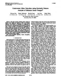
2. Overview of SHOALS target detection For bathymetric lidar, many factors contribute to the ability and probability of detecting underwater targets, including target dimensions, water depth, water clarity, system configuration, survey planning, and data processing, as well as sophisticated algorithms to automatically identify bottom anomalies. One of the most obvious factors affecting bathymetric lidar surveys is water clarity, which not only limits the maximum measurable depth, but also considerably affects underwater target detectability. For detecting underwater targets with limited dimensions, lidar point density also plays a significant role. In general, two key factors define target detectability within a laser footprint: 1) the probability that the target will be illuminated (wholly or partly) by the laser footprint, which depends on the effective laser footprint size and lidar point density; 2) the ability to identify the target return signal from its surroundings, which depends on the significance of the target return signal and the sensitivity of the target detection algorithm to discern target signatures. In 1996, Gary Guenther et al [3] conducted a theoretical study on the performance of bathymetric lidar in underwater obstruction detection, based on parameters and algorithms in use at that time. Multiple scenarios with different target dimensions, water conditions, and lidar point densities were discussed in that study, which resulted in predictions of target detection probabilities under various scenarios for the SHOALS system. As an example, Figure 1 shows the analytical results of detection probabilities for 4-m2 circular cylinders in various water clarities, with 1-m and 2-m target heights, using 4 m × 4 m lidar point density. Apparently, objects with 2-m height and 4-m2 surface area can be detected with almost unit probability in clear water conditions, even with 4 m × 4 m spot spacing, which meets the IHO-1 requirements. It is noteworthy that the criteria for positive target identification are based on either distinctive bottom peak separation (Type-1 detection) or a correct reading of least depth from the merged bottom peak (Type-2 detection). Type-1 detection occurs when the return signals from both the target and the water bottom can be discerned separately and measured using the traditional depth extraction algorithms. Type-2 detection occurs when the return signal from the target surface area overshadows that of the water bottom.
2
Figure 1: Detection probabilities for 4-m2 circular cylinders in various water clarities, with 1-m and 2-m target heights, using a 20-degree nadir angle and 4m*4m lidar point density. [3]
The practical experience of many SHOALS users supported and frequently exceeded the performance expectation of the analytical predictions and demonstrated that airborne lidar bathymetry is commonly capable of detecting small features and targets to meet IHO-1 requirements. [2][4][5] Since 1996, SHOALS has undergone substantial upgrades in hardware, software and algorithms [6], which has enhanced its performance in underwater target detection. With the addition of higher point densities, up to 2 m × 2 m spot spacing, the geometric searching capability has drastically improved, with virtually 100% bottom illumination by a single coverage. Most important, Optech’s latest efforts to improve the target detection algorithm, whose predecessor was merely a by-product of traditional depth extraction algorithms, have revealed that the SHOALS system is much more capable than was initially predicted [3] in terms of target resolution and detectability when the sophisticated algorithm is used. The significant enhancement in SHOALS’ target detection capability is therefore primarily due to algorithmic advances in identifying abnormal bottom returns, with experience built upon Optech’s latest success with the shallow water algorithm (SWA) [7]. However, different analytical perspectives were also introduced to explain the empirical results of enhanced SHOALS target detectability.
3
3. Enhanced target detection The SHOALS system has been configured in such a way that the laser beam strikes the air/water interface with a footprint size of about 2 m and a constant incident angle of about 20°[8]. Although such a configuration originally considered eye-safety, depth penetration, water surface detectability, and minimization of propagation biases, it is also beneficial for underwater target detection in terms of geometric searching, object differentiation, and consistency across the scan swath. Because the laser beam further expands in the water column, often significantly, owing to scattering from entrained particulates, it ensures that 100% bottom illumination is achievable even with a lesser lidar point density, such as 3 m × 3 m. Furthermore, with the current configuration of the SHOALS-1000 system, the programmable scanner patterns allow lidar point density to vary from 2 m ×x 2 m to 5 m × 5 m [6] (Table 1). Table 1: Scanner Patterns for SHOALS-1000T Hydro subsystem Altitude
Swath (m)
Lateral Spot Spacing (m)
Forward Spot Spacing (m)
Flight Speed (knots)
(m)
Area Coverage (km2/hr)
400
60
2
2
124
13.8
300
60
2
2
124
13.8
200
60
2
2
122
13.6
400
130
3
3
127
30.6
300
125
3
3
128
29.6
200
110
3
3
124
25.3
400
215
4
4
126
50.2
300
165
4
4
162
49.5
400
230
5
5
180
76.7
300
174
5
5
180
57.9
Table 1 shows the available survey patterns and nominal lidar point densities of the SHOALS-1000 hydrographic subsystem. Since the laser footprint is purposely expanded to a 2-m diameter, the available patterns of SHOALS-1000 ensure 100% bottom illumination in a single coverage throughout the measurable depth range, regardless of water depth and water clarity. This means that SHOALS-1000 is virtually a complete bottom imager from shallow to deep water, capable of illuminating every single rock or object sitting on top of a relatively flat bottom surface. If 100% bottom illumination is assured by using suitable point density patterns, target detectability relies on the capability of identifying a target from its return signal, which is usually compounded by the return signal from the water bottom. Traditionally, the approach to identifying a target involves resolving distinguishable return signals from both the target and water bottom. This works in cases where the target dimensions are
4
greater than what can be resolved by the traditional pulse location algorithms [3]. Because the laser footprint is usually greater than 2 m in diameter when reaching the water bottom, depending on water depth and water properties, targets the size of 2 m cubes (or smaller) are usually covered entirely by laser footprints, introducing distortions to the return signal normally dominated by the bottom return signal. If such distortion is significant enough to produce a separate and resolvable return signal from the target surface, it will be recognized as a target by the traditional method, with certain sensitivity. In cases where a target is significantly larger than the laser footprint, the return signal from the target may be reflected entirely from the top of the target with no sign of distortion. However, such targets will also be identified in the lidar point clouds because of their raised elevations. In general, targets larger than the laser footprint will always be captured, whereas targets comparable to the size of the laser footprint will usually be recognized by the traditional method of target identification. Similar to the traditional depth extraction algorithms, which require clear separation of surface and bottom returns, the traditional method of target detection is limited by its ability to identify smaller objects that are insufficient to produce separate target and bottom returns. Figure 2 shows two waveforms from two underwater targets sitting sideby-side at a depth of about 9 m. These two targets were man-made objects with known dimensions.
Figure 2: Sample waveforms from two targets of different size sitting side by side under about 9 m of water. The waveform at left is from a 1-m cube; the waveform at right is from a 2-m cube. The waveform on the left is from a 1 m cube, whereas the waveform on the right is from a 2-m cube. Apparently, the 2-m cube produced clear separation between the bottom return (marked with a blue dot) and the target return (marked with a red dot), and would be identified by the traditional method of target identification. However, the waveform produced by the 1-m cube showed only a single peaked bottom return with an inflection
5
at the leading edge of the bottom signal. This kind of waveform would not be tagged by any of the traditional algorithms; therefore it would derive a normal bottom elevation (or water depth) without notice. As a matter of fact, the location of the blue dot indicates that this waveform will result in an elevation (or water depth) referenced to the true bottom, which means the existence of the target is totally ignored. No matter how carefully the bottom surface and lidar point clouds are examined and analyzed, this 1-m cube would be completely invisible. The enhanced target detection algorithm takes into consideration the situation shown in Figure 2, as well as many other variants of distorted bottom return signals from bottom features. The basic approach of the enhanced target detection algorithm is that any illuminated objects will impinge their signatures in the waveforms captured with their presence, which will then trigger a sophisticated algorithm for target recognition. Based on the assumption of 100% bottom illumination, any targets larger than the laser footprint will be visible in the lidar point clouds (Case 1 targets); any targets of comparable size to the laser footprint (i.e., similar to a 2-m cube) will mostly be identifiable by the traditional method of target detection (Case 2 targets); all targets other than those captured by Case 1 and Case 2 will be designated as Case 3 targets, which include targets with dimensions ranging from 2-m cubes (not captured by Case 2) to targets as small as 0.5-m cubes. Noteworthy also is that the recognition of Case 2 and Case 3 targets is based on a single waveform, which means that the SHOALS enhanced target detection algorithm observes small objects within the small field of view (FOV) of the receiver telescope. This is an innovative concept in contrast to the conventional wisdom of applying the “Nyquist criterion”[4][9]. The SHOALS configuration of relatively large laser footprint and multiple FOV has effectively increased the target detection capability if the return signal from each individual lidar sounding is carefully analyzed. Based on the understanding that the transmitted laser pulses have constant shape and that the propagation-induced pulse stretching is reasonably small and predictable, the enhanced target detection algorithm is capable of detecting distortions to the bottom return induced by bottom features in the scale of 0.5 m (about 5 ns in the digitizer waveform scale). This allows the detection of small objects at the same scale. Overall, the enhanced capability of SHOALS target detection is a result of both hardware advancement and algorithm development. The hardware advancement results in higher laser pulse repetition rates, higher point density and complete bottom illumination, whereas the algorithm enhancement ensures effective identification of bottom features, with unit probability in clear water.
4. Case studies The enhanced target detection algorithm was developed based on an understanding of SHOALS’ lidar return characteristics, which have been tested under various environmental conditions. There are numerous examples to illustrate the algorithm’s
6
ability to identify bottom features and anomalies, such as small objects sitting on the water bottom. Figure 3 shows a case (from Saipan, Philippines) surveyed with a pattern of 300 m altitude and 3 m × 3 m spot spacing where four lidar soundings were identified and automatically highlighted as small objects by the enhanced target detection algorithm, with waveforms (from two different flightlines) displayed under the point cloud. In the past, this kind of waveform was not detectable; therefore, the corresponding small object would be totally ignored. However, with the enhanced target detection algorithm, the subtle signatures of even sub-meter targets will be detected in the bottom return signals. If a survey is properly planned to ensure 100% bottom illumination, all targets larger than a certain detection threshold will be captured, with 100% probability. Such detection thresholds are currently set at 1 m and 0.5 m respectively for different detection sensitivities in the enhanced target detection algorithm.
7
Figure 3: Lidar points from two overlapping flightlines. A sub-meter small object is detected and automatically highlighted by the enhanced target detection algorithm in both flightlines. The yellow triangles highlight the lidar points identified as hitting a target, with waveforms shown under the point cloud. Combined with the traditional method of target detection, which is to monitor separate peaks in the bottom returns, the enhanced target detection algorithm is capable of detecting targets of all sizes. The following examples demonstrate the overall performance of SHOALS-1000 target detection capability. In the 2003 acceptance tests of the SHOALS-1000 system in Florida [6], ten 2-m cubes similar to the one shown in Figure 4, and multiple 1-m cubes, were constructed and placed on the sea bottom in two east-west lines named “southern target line” and
8
“northern target line” at depths ranging from 5 m to 28 m. Multiple flightlines were flown over these two target lines with various survey patterns.
Figure 4: Single flightline (300 m altitude, 2 m × 2 m spot spacing) over southern target line, where a pair of targets (2-m cube and 1-m cube) under about 10 m of water is automatically detected and highlighted. Figure 4 shows a 2D lidar point view of a single flightline flown over the southern target line at 300 m altitude, with a 2 m × 2 m spot spacing pattern. In the displayed lidar points, two targets (under about 10 meters of water) are highlighted by yellow triangles, one of which is a 2-m cube, and the other a 1-m cube. In this case, the enhanced target detection algorithm identifies the 1-m cube by three suspect markers, and locates the 2-m cube by eight of them. This indicates that a single flight pass is sufficient to detect 1-m and 2-m cubes at an altitude of 300 m, and a spot spacing pattern of 2 m x 2 m in water conditions typical of this part of the Florida coast. Figure 5 is a 3D view of lidar points along the southern target line, also from the 2003 field trial of the SHOALS-1000 system in Florida [6]. Multiple targets are visible by their vertical offsets from the sea bottom and their diamond shapes. The lower targets highlighted are pairs of 1-m and 2-m cubes sitting on top of the sea bottom, whereas the higher ones are long targets suspended 5 m above the sea bottom. Sample waveforms of the long targets and the 1-m targets are also displayed in the image as references.
9
Figure 5: A profile view of lidar points from the southern target line collected in the 2003 SHOALS-1000T field trial in Florida. All targets placed along the southern line are automatically identified and highlighted, including 1-m cubes, 2-m cubes and long targets suspended in the water column. Sample waveforms are displayed as references.
5. Discussion Small object detection is a very important part of hydrographic surveys, but it is also complicated for both sonar and lidar because the detection probability depends on multiple factors. With the addition of the enhanced target detection algorithm, SHOALS has significantly improved its target detectability of smaller objects. However, its dependency on water clarity still remains. Empirically, SHOALS is capable of detecting targets greater than 1-m cubes within 2-Secchi depths 100% of the time; whereas the target detectability is optimized in water depths ranging from 0 meters to about 18 meters. Such empirical results can be explained by the fact that the shallow green channel of the SHOALS system has a limited FOV of 15-mrad, which enhances target contrast in its measurable depth range of 0-18 m. The limit of 2-Secchi depths relies on the achievable sensitivity of the enhanced target detection algorithm that allows reliable differentiation of the target return from the bottom return. The analytical study by Gary Guenther et al [3] assumed infinite FOV of the receiver channel, although the paper mentioned that limited FOV would increase the target contrast. As a matter of fact, the FOV plays a very significant role in target detection. For example, an altitude of 200 m results in an observing window of only 3 m in diameter with a 15-mrad FOV. This implies that the effective footprint size visible to the receiver 10
is reduced to a much smaller size than that of the expanded laser footprint [8][10]. Such an impact of the FOV further consolidates SHOALS’ ability to detect objects greater than 1m cubes under most environmental conditions, with unit probability to about 2-Secchi depths. Another point of discussion is laser beam expansion in various water conditions, which has been assumed as approximately half of the water depth. This assumption is believed to be an overestimate in clear water. Studies [8][10] indicate that expansion of the laser beam could be as low as 20% of the water depth in optically shallow water, which significantly decreases the effective laser footprint on the water bottom. If that is the case, it also explains the enhanced contrast of target return signal versus the return signal from the surrounding bottom. Based on the above analysis, combined with the requirement for 100% bottom illumination, the practical guidelines for rapid reconnaissance of small underwater obstructions would be: 1) a 300-m altitude, 3 m × 3 m spot spacing pattern is efficient and optimized for detecting objects larger than 1-m cubes; 2) a 200-m altitude, 2 m × 2 m spot spacing pattern provides a thorough inspection of all underwater small objects, and has the capability of detecting objects as small as 0.5-m cubes; 3) target detectability depends on water clarity, but the rule of thumb is that any targets within 2-Secchi depths will be reliably detected with unit probability. The enhanced target detection algorithm is based on a signal observed within a small FOV, which assumes a flat water bottom. There are cases where distortions of bottom returns are triggered by sudden bottom slopes, which can lead to mislabeling of such bottom anomalies as small targets. Usually, mislabeled bottom anomalies are associated with very rugged water bottoms or neighboring areas surrounding a much larger bottom feature, where user inputs through 3D editing are required to identify isolated targets. Nevertheless, the enhanced target detection algorithm is capable of highlighting all suspected lidar points. During development of the enhanced target detection algorithm, major improvements were made to the mechanism of target identification. Initially, any lidar return with a second depth was classified as a target, which resulted in a very high rate of “false alarms” due to noisy waveforms, especially within the water column. Such false alarms, sometimes dominating the highlighted suspects, overshadowed the ability to observe true bottom features, and degraded the overall performance of the system’s target detection capability. With the new enhanced target detection algorithm, any water column-induced second depth is carefully examined to reject false alarms. Overall, SHOALS’ target detection capability is built on successfully identifying three different types of bottom features: Case-1 targets, which are obvious in the lidar point cloud; Case-2 targets, which are identified by distinguishable target and bottom returns using the traditional pulse location algorithms; Case-3 targets, which differentiate bottom anomalies by examining distortion in the bottom returns. Case-3 handles all situations
11
that are not handled by both Case-1 and Case-2, and enables detection of targets as small as 0.5-m cubes. Also noteworthy is the fact that the SHOALS-3000 system will effectively triple the survey efficiency with the same level of target detection capability.
6. Conclusion Both empirical and analytical results indicate that SHOALS is highly capable of detecting small objects underwater. Empirical studies indicate that, under clear water conditions, SHOALS exceeds IHO-1 requirements for underwater target detection and, with proper survey planning, can easily meet IHO Special Order requirements. Considering the efficiency and cost effectiveness of using airborne bathymetric lidars such as SHOALS, it is obvious that this is the technology of choice for the rapid reconnaissance of small underwater obstructions in shallow coastal water. The enhanced target detection capability also suggests that SHOALS system has great potential for military applications in the rapid reconnaissance of submarines, underwater mines and any other objects of interest as small as 0.5 m in diameter.
References [1] International Hydrographic Organization, 1998, IHO Standards for Hydrographic Surveys, Special Publication No. 44, 4th Edition. [2] West, G.R. and Lillycrop, W.J. 1999. Feature Detection and Classification with Airborne Lidar - Practical Experience, Proc. Shallow Survey 99, October 18-20, Sydney, Australia. [3] Guenther, G.C., Eisler, T.J. Riley, J.L. and Perez, S.W. 1996. Obstruction detection and data decimation for airborne laser hydrography, Proceedings, 1996 Canadian Hydrographic Conference, Halifax, N.S. 51-63. [4] Guenther, G.C., 2007. A letter to the editor, International Hydrographic Review. [5] Lockhart, C., Arumugam, D., Millar, D., 2005. Meeting Hydrographic Charting Specifications with the SHOALS-1000T Airborne LiDAR Bathymeter, Proceedings of the 2005 U.S. Hydrographic Conference, San Diego, CA
[6] LaRocque P.E., Banic, J.R. and Cunningham, A.G. 2004. Design description and field testing of the SHOALS-1000T airborne bathymeter, Proc. SPIE Vol. 5412, Laser Radar Technology and Applications IX; Gary W. Kamerman; Ed. p162-184. [7] Yang, E., LaRocque P.E., Guenther G.C., Reid D., Pan W., Francis K., 2007. Shallow water depth extraction – progress and challenges, Proceedings of the 2007 U.S. Hydrographic Conference, Norfolk, VA [8] Guenther, G.C., 1985: Airborne laser hydrography: system design and performance factors, NOAA professional paper series, 1. Rockville, Md: U.S. Dept. of Commerce, National Oceanic and Atmospheric Administration, National Ocean Service, Charting and Geodetic Services, 385 pp. 12
[9] Smith, S.M., 2006, “Empirical Object Detection Performance of LIDAR and Multibeam Sonar Systems in Long Island Sound”, International Hydrographic Review Vol. 7 No. 2, July 2006 [10] Kopilevich, Y., Tuell, G., Feygels V., 2005. Aspects of resolution and target detection, 6th Annual Airborne Coastal Mapping and Charting Workshop, July 2005, Philadelphia, PA.
13