Unified framework for generation of 3D web ...

1 downloads 218 Views 2MB Size Report
The library Three.js do not directly supports X3D format, thus the framework contains ... to the size of the screen on the device(desktop, tablet, mobile phone, etc.) ...
Home

Search

Collections

Journals

About

Contact us

My IOPscience

Unified framework for generation of 3D web visualization for mechatronic systems

This content has been downloaded from IOPscience. Please scroll down to see the full text. 2015 J. Phys.: Conf. Ser. 659 012053 (http://iopscience.iop.org/1742-6596/659/1/012053) View the table of contents for this issue, or go to the journal homepage for more

Download details: IP Address: 147.228.47.91 This content was downloaded on 09/02/2016 at 15:28

Please note that terms and conditions apply.

12th European Workshop on Advanced Control and Diagnosis (ACD 2015) IOP Publishing Journal of Physics: Conference Series 659 (2015) 012053 doi:10.1088/1742-6596/659/1/012053

Unified framework for generation of 3D web visualization for mechatronic systems O. Severa, M. Goubej and J. Konigsmarkova NTIS, University of West Bohemia, Pilsen, Czech Republic E-mail: {osevera, mgoubej, jkonig}@ntis.zcu.cz Abstract. The paper deals with development of a unified framework for generation of 3D visualizations of complex mechatronic systems. It provides a high-fidelity representation of executed motion by allowing direct employment of a machine geometry model acquired from a CAD system. Open-architecture multi-platform solution based on latest web standards is achieved by utilizing a web browser as a final 3D renderer. The results are applicable both for simulations and development of real-time human machine interfaces. Case study of autonomous underwater vehicle control is provided to demonstrate the applicability of the proposed approach.

1. Introduction Computer aided development (CAD) has become a standard in many industrial automation domains including mechatronics, robotics and motion control systems. Various supporting software tools are used in the individual stages of the prototype development cycle. This process typically involves a set of subsequent steps: (i) (ii) (iii) (iv) (v) (vi) (vii) (viii)

Problem formulation Mathematical model synthesis Mechanical design Control system design Employment of visualization framework Model and hardware-in-the-loop (MIL, HIL) simulation (preferably with 3D visualization) Prototype manufacturing Implementation of control system and human-machine interface (HMI) (preferably with 3D visualization)

The geometric modelling is carried out in some of the available CAD systems. Several alternatives exist for the mathematical modeling part such as Matlab/Simulink/Simscape by MathWorks, MapleSoft Maple, Wolfram Mathematica and Mathmodelica, OpenModelica or Dymola and special plugin toolboxes e.g. [1], [2], [3]. These tools can be used in the stages of model, software, processor and hardware-in-the-loop simulations (see [4] for detailed description of the individual simulation types). Validation of the model and control system is followed by manufacturing of the prototype and implementation of the control algorithms into a target hardware platform. Content from this work may be used under the terms of the Creative Commons Attribution 3.0 licence. Any further distribution of this work must maintain attribution to the author(s) and the title of the work, journal citation and DOI. Published under licence by IOP Publishing Ltd 1

12th European Workshop on Advanced Control and Diagnosis (ACD 2015) IOP Publishing Journal of Physics: Conference Series 659 (2015) 012053 doi:10.1088/1742-6596/659/1/012053

An important part of the development cycle is proper visualization of controlled plant behavior. This is essential both for simulations and real machine operation when dealing with complex mechatronic systems. High fidelity three dimensional representation of the executed motion using a geometric model acquired from the CAD system can simplify the process of simulation or real machine diagnostics by revealing possible bottlenecks in mechanical and control design. The above mentioned modeling and simulation tools offer several possibilities of connection of the mathematical model with the 3D machine geometry. However, the visualization tools cannot be simply used for both real-time HIL simulations and development of the HMI for the final prototype system. On the other hand, most of the commercial HMI tools for industrial use (InTouch by Wonderware, GENESIS by Iconics, WinCC by Siemens, etc.) are focused on the data processing. One can create extensive HMIs with multiple nodes, but usually the HMI is bound to some vendor specific client application and there is a limited support for direct employment of the CAD geometric model. Moreover, commercial software tools are burdened with high license fees. Therefore, there is a need for a cost-effective open-architecture system which • • • •

is able to import models from various CAD systems, provides a high-fidelity real-time 3D visualization, is multiplatform, can be connected both to simulation model and real plant (preferably without significant changes in the HMI configuration)

The paper presents a unified framework based on latest web technologies which is intended for generation of 3D visualizations for mechatronic systems. Its development is built on the previous results described in [5] and [6]. The main purpose of the framework is to support rapid prototype development. Platform-independent solution is achieved by employing web browser as the final 3D HMI renderer. This allows to run the HMI on desktops with various operation systems, on tablets or even mobile phones. It can be connected both to a simulation model and real-time control system using a proper communication interface. A case-study of HMI development for autonomous underwater vehicle is provided to demonstrate the applicability of the proposed approach. The paper is organized as follows: section 2 describes the individual components of the tool chain, section 3 shows the employment of the developed framework on the example of underwater vehicle. Finally, some concluding remarks and possible directions for a future research are given. 2. Framework for 3D web visualization of mechatronic systems

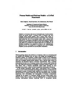
Figure 1: From CAD to 3D visualization

2

12th European Workshop on Advanced Control and Diagnosis (ACD 2015) IOP Publishing Journal of Physics: Conference Series 659 (2015) 012053 doi:10.1088/1742-6596/659/1/012053

The framework extends the described prototype development steps with step 5 (Employment of visualization framework ) and adds 3D HMI both for MIL and HIL simulations (step 6). Finally the same 3D HMI can be used for the final product (step 8). The overall view on the whole procedure of 3D HMI creation is depicted in Fig. 1. At the beginning, there is a CAD drawing of the mechanical part of the machine/robot. Then, the model is exported to a 3D exchange format. There are plenty of exchange formats like STEP, IGES, DXF, Parasolid XT, DRG, etc. but only some of them are suitable for 3D HMI because the format must preserve materials and hierarchy of the model. For the framework, the STEP format was chosen. Closer description of reasons will follow. When the model is exported from CAD system, it must be converted to a web supported format, simplified and tagged for animation. Some of the actions are done automatically, some of them must be done by user / developer. Once again, there are several web supported 3D formats like X3D, VRML, COLLADA, etc. For the unified framework, the X3D was chosen since it is very similar to SVG, further explanation will follow. When the 3D model is ready, it must be bound with a simulation / control system core. The Inkscape editor with HMI extension is used for this purpose. One just connects the chosen parts of the 3D model with signals from the core and sets appropriate animations rules. After the configuration is done, finally the 3D model is embedded to a HTML5 enabled web page automatically. Such a page can be served via a web server or run locally from the file system. STEP - 3D exchange format The whole visualization is based on the 3D model which was exported from CAD (Computer aided design) system. There are several 3D exchange formats, where STEP (Standard for the Exchange of Product model data) is one of the most supported. This format is standardized under ISO 10303-21. Description of the 3D scene like volumes, hierarchy, materials, etc. is written in the text form using EXPRESS data modeling language. The main advantages of the STEP format are wide support from various CAD systems and the fact that the export preserves model hierarchy and materials (colors, opacity, shininess, etc.). The hierarchy of components of the model is very important especially for animation. The main disadvantage of the STEP format is that there is no suitable 3D web renderer which supports this format directly. Thus, further modifications are necessary for preparation of the model for visualization purposes. Three.js - WebGL renderer There are several ways how to render 3D objects inside the webpage. Few years ago, the only way how to render 3D was to use third-party plugins such as Java applets [6], Adobe Flash plugins or various ActiveX components. Nowadays, the WebGL [7] is available. This technology allows to render 3D graphics directly in a webpage without any plugin. WebGL can be directly used from JavaScript, but there are also libraries built on top of the low level WebGL API. Project Three.js was used in this case. This open-source library is still in development process by wide community. It allows developer to easily render scenes, control cameras and animations, control lights, shadows, etc. This library supports also scene import in several formats. The whole web rendering segment is under extensive development, thus described technologies are not fully supported in every web browser. It means that the visualization can be used only in advanced browsers i.e. Google Chrome / Chromium project, Mozilla Firefox or latest versions of Internet Explorer and Microsoft Edge browser. Blender / Vivaty Studio - 3D editor During the 3D HMI development process it is necessary to simplify and adjust the hierarchy of the 3D model. This can be done manually or using available 3D editor. In the previous version of the framework, the Vivaty Studio was used to adjust hierarchy of the model. Since the software is no longer supported the Blender (free and 3

12th European Workshop on Advanced Control and Diagnosis (ACD 2015) IOP Publishing Journal of Physics: Conference Series 659 (2015) 012053 doi:10.1088/1742-6596/659/1/012053

open source 3D creation suite) is used. Both programs support hierarchy rearrangements, model simplification and overall editing functions. The final 3D model is then exported back to the X3D format. Inkscape - the vector graphic editor The last tool in the row is Inkscape which is free and open source professional vector graphics editor for Windows, Mac OS X and Linux. It support creation and editing of vector graphic stored in Scalable Vector Graphics (SVG) format. The SVG is a XML-based vector image format for two-dimensional graphics with support for interactivity and animation. The SVG specification is an open standard developed by the World Wide Web Consortium (W3C) since 1999. Current version of the SVG specification is 1.1 standardized on 16th of August 2011 [8]. SVG is supported in all modern browsers (IE, Chrome, Firefox, Opera, etc.). The Inkscape in the 3D framework is used only as a supporting tool. It is extended with several plugins which help user / developer to configure and design the final 3D HMI. One can create the 3D HMI without the extended Inkscape but it requires more manual coding in HTML and Javascript. The description of extension is given in subsection 2.1.2. HTML5 and Javascript libraries Final 3D HMI is running inside web browser thanks to the HTML5. HTML5 is specification for web pages which supports e.g. semantic elements like
,
,
,
, form control attributes, multimedia elements like , and finally graphic elements and . The element in this case uses WebGL (Web Graphics Library) which is a JavaScript API for rendering interactive 3D and 2D graphics within any compatible web browser without the use of plug-ins. WebGL does so by introducing an API that closely conforms to OpenGL ES 2.0. Except plain HTML, the client application uses scripts in JavaScript. These scripts are responsible for interaction of the webpage with the user. There are several libraries in use. For example jQuery [9] is an extensive library for DOM (Document object model) manipulation. This library allows easy manipulation with all nodes of the DOM. The next section describes how the whole development from user/developer point-of-view is done. 2.1. Development of the 3D HMI In the Fig. 1 is shown that the first step for 3D HMI is a 3D model of the visualized machine or robot designed using CAD tool. Usually the designer creates the whole system with all the necessary components including gears, screws, nuts, cables, etc. Thus, a semi-automatic conversion is needed. 2.1.1. Preparation of the 3D model When the model is exported to the STEP file format, it must be converted to the X3D. Such a conversion can be done by several tools. One of them is a CAD Exchanger which we use in this case. Unfortunately, it is not open source software, so there is a room for improvements. The next step is adjustment of the hierarchy of the model in 3D editing software. It is a semi-automatic process in Vivaty Studio / Blender, where one needs to create group of the components for the animation. Each group need to contain all the elements which animates together. For example the underwater vehicle has 8 motors. Each of them has a propeller, so each propeller represents one group which will rotate, consequently each motor is inside of a machine group which will rotate and translate simultaneously, see the use case section for more details. In 3D HMI, the selected nodes/elements/groups are animated according to data from the simulation/control core. These selected nodes must be tagged. This is done via Inkscape extension which allows configuration of the animation and interconnection of the signals (see

4

12th European Workshop on Advanced Control and Diagnosis (ACD 2015) IOP Publishing Journal of Physics: Conference Series 659 (2015) 012053 doi:10.1088/1742-6596/659/1/012053

the following subsection). Finally, the 3D model is loaded to the WebGL renderer inside the webpage. The library Three.js do not directly supports X3D format, thus the framework contains special loader for X3D files. This loader allow users to load large X3D files (more than 10 MB) into the browser DOM and to convert them into the inner Three.js 3D representation as a source for the WebGL renderer. During the loading process, the connection to the simulation/control core is established and the selected nodes are animated based on the HMI configuration.

Figure 2: Inkscape with HMI configuration extension 2.1.2. Web-page design One has several ways how to design a webpage (HMI) for various virtual models or real devices. First one is to implement everything by manual coding using HTML language. The unified framework contains ”low level” javascript API which allows interconnection between the simulation/control core and the HMI. However, such an option is meant only for special adjustments. For fast prototyping of the simulator, several extensions for Inkscape vector graphic editor were developed. Basic principle for any HMI created by the framework is a single page which scales according to the size of the screen on the device(desktop, tablet, mobile phone, etc.). This presumption allows to create multiplatform and multidevice HMIs. When one run the Inkscape editor there is only one main page. All the components inserted to the page will be automatically generated to the web page in the corresponding positions. There are several extensions written in Python language which support such a behavior. The whole concept uses SVG components with javascript files which control the final HMI behavior. These two files are called HMI module. Each module contains configuration (inside SVG file) and control part (JavaScript file). The configuration is stored in SVG file inside the element in JSON (Javascript Object Notation) format. When user inserts new component to the page, the configuration is cloned and then one can use the HMI extension for Inkscape to alter it. When the page is ready, it is exported to the final HTML file. There is a basic template which contains all the necessary libraries like jQuery, Three.js and at last the HMI library for

5

12th European Workshop on Advanced Control and Diagnosis (ACD 2015) IOP Publishing Journal of Physics: Conference Series 659 (2015) 012053 doi:10.1088/1742-6596/659/1/012053

the framework. This template is extended with all the javascript controllers for HMI modules inside the webpage. When the HTML file is loaded to the browser, the HMI library traverses all components and starts appropriate controllers. There are several HMI extensions for Inkscape, the most important is called the Element editor. Following list will explain what are the extensions used for. Element editor is an extension (shown in Fig. 3) which is used for editing properties of HMI

Figure 3: Inkscape with element editor extension modules. It changes the JSON configuration inside the element inside the SVG (HMI module). One can edit Title, Module, Options and Connections using this tool. • Title is shown in the web browser after hovering the cursor above element and is also used in Connections as shortening, during the initialization is the wildcard $T replaced by the title. • Module identifies uniquely the type of component and assigns the proper JavaScript functionality. • Connections tab contains names of signals that trigger the element behavior. • Options tab edits the additional options of the component. HMIConfig editor is similar to the Element editor. The options for the whole visualization project are edited here. HMIConfig editor is shown after calling the Element editor with no element selected. It contains three main tabs Connections, Options, HTML export. • Connections are the signals used in visualization assigned to the signals from the simulation/control core. If there is a proper scheme already executed in the core, the signals might be browsed online. • Options tab contains an IP address of the target device and other options for the whole project. • HTML export tab contain configuration of the web page exporter. Library Browser extension just opens the windows explorer with the selection of HMI modules. 6

12th European Workshop on Advanced Control and Diagnosis (ACD 2015) IOP Publishing Journal of Physics: Conference Series 659 (2015) 012053 doi:10.1088/1742-6596/659/1/012053

HTML Builder extension builds the web site into the target folder, in case the valid location is set in the HMI Configuration menu. This extension unzips the webpage template and inserts the content of the current SVG project. It also loads all the javascript controllers for the used modules and links them to the page. Such a exported project can be run from webserver or locally from generated file. Group animation is the last extension (shown in Fig. 4) which is different from all the previous ones. It creates a HMI module from any group by defining its behavior (translation, rotation and changes of color, size and opacity). Such a module can be then edited by Element editor.

Figure 4: Group animation component 3D HMI module represents one of the modules. In this case the Inkscape editor user just create the placeholder for the Three.js 3D canvas. Then the Element editor is used to adjust connections for selected nodes and configuration for animation assigned to those nodes. 2.1.3. Communication The 3D HMI uses the client server architecture (depicted in Fig. 5). Client (Web Browser) is connected through Socket TCP/IP connection to the special server which translates data from and to the simulation / control core. This type of direct webpage communication is called WebSocket [10].

Figure 5: 3D HMI communication schema

7

12th European Workshop on Advanced Control and Diagnosis (ACD 2015) IOP Publishing Journal of Physics: Conference Series 659 (2015) 012053 doi:10.1088/1742-6596/659/1/012053

The HMI also partially supports communication over REST web services, but this direction is planned for future version of the framework. The communication uses data messages serialized into JSON format. Current version of the simulation core and following control algorithm is done using REX Control system, so the WebSocket communication protocol is designed for the system as well. On the other hand the 3D HMI is build independently so with slight adjustments of the communication component it can be connected to different simulation and control cores. 3. Case-study: Prototype of underwater vehicle This visualization technology was used during the development of underwater vehicle for Non Destructive Testing inspection, for a more detailed description see [11]. The vehicle was designed as a neutrally buoyant rigid body and works in two modes - the remote operated vehicle (ROV) and the autonomous underwater vehicle (AUV). An important part of this vehicle is a platform with phased array probe for weld testing. The whole vehicle is designed to be symmetrical with symmetrical arrangement of thrusters - four thrusters in the horizontal vehicle plane and four thrusters in the vertical plane. The prototype construction and thrusters configuration are depicted in Fig. 6. The mathematical model was created in Matlab/Simulink and implemented in real time control system REX. The model is used for hardware in the loop simulations. This use case shows how the mathematical model of the vehicle is extended with 3D HMI such that MIL and HIL simulations seem closer to the reality.

Figure 6: Symmetrical thrusters configuration.

3.1. Real-time simulation core The real-time simulation is realized by REX Control system [12]. REX implements a software PLC supporting Function Block Diagram (FBD), Sequential Function Chart (SFC) and C-like programming language. The REX implementations of FBD and SFC are with a few exceptions compatible with IEC 61131-3 and the C-like language substitutes Structured Text language from IEC 61131-3. Since the REX Control system blocks are compatible with MATLAB/Simulink, the first drafts of the simulator and control can run directly inside MATLAB environment using REX Lib library [13]. 3.2. Mathematical model To simulate the vehicle motion in the real time and with sufficient accuracy, some useful but nonrestrictive simplifications were introduced in the construction design and motion description. The shape of the vehicle is considered almost cubic, with coincident center of gravity (CG) and center of buoyancy (CB), so the hydrodynamic effects will be very similar in all principal axes. 8

12th European Workshop on Advanced Control and Diagnosis (ACD 2015) IOP Publishing Journal of Physics: Conference Series 659 (2015) 012053 doi:10.1088/1742-6596/659/1/012053

A low velocity of the vehicle is assumed, therefore the viscous effects can be modeled as a drag in the form of damping and the added mass as well as inertia parameters are modeled as external forces. The dynamics of the submerged vehicle can be described by the Kirchhoff’s motion equations [14]. By following considered simplifications, the translation and rotational motion can be decoupled. The dynamic equations of motion (detail described in [11]) lead to the system of nonlinear ordinary differential equations with the state variables - position and velocity of the center of gravity in the inertial frame and the rotation angles roll, pitch and yaw of the vehicle and their derivatives. The system is solved by numerical Runge-Kutta method of 4th order, which seemed to be sufficiently accurate and fast. The dynamic equations together with the numeric method are implemented in the real time control system REX [12] as a block ROUV (Remotely Operated Underwater Vehicle). 3.3. Control system The controlled variables are the velocities in the body fixed frame - in surge and sway directions, the derivative of yaw, the depth and the angles roll, pitch and yaw. For movement in camera direction we can use the velocity in heave direction. The thrusters were collected to the virtual inputs according to their effect on the vehicle motion. The stabilization control law is provided by six PID controllers whose parameters were determined by the pole placement method for the transfer function obtained from the linearized model. The poles were selected according to the maximal real stability radius criterion for the system to be sufficiently robust and assigned in the way to ensure similar properties for variables with similar sense. The control scheme of Remote Operational Underwater Vehicle is shown in Fig. 7, the visualization of the controlled model is in Fig. 9.

v*

C vPID

v2*

C ω3*

C

PID v2

Input conversion (virtual→physic)

1

u1

pitch roll

v1*

depth

Horizontal thrusters control

mode

pitch*, roll* C OC depth*

u2 u3

v1 * v2 * v3 * ω1* * ω2 ω3*

PID

u5 u6

ROUV

u4

Vertical thrusters control v3 *

Cv

u7 u8

Input conversion (virtual→physic)

ω*

ρi

PID 3

PID 1

C R

C

Figure 7: Control scheme of ROUV.

9

3

PID 2

ω1*

ω2*

12th European Workshop on Advanced Control and Diagnosis (ACD 2015) IOP Publishing Journal of Physics: Conference Series 659 (2015) 012053 doi:10.1088/1742-6596/659/1/012053

3.4. 3D Human–machine interface The 3D HMI for the simulator and as well as real device was created using the described framework. At the beginning there was CAD drawing with simple hull and proper drawing of motors. One can see (in Fig. 8) that the drawing is already imported to the Vivaty Studio (a tool for hierarchy adjustment). After the X3D sceen was created (after simplification and proper hierarchy adjustment), the layout of the webpage was designed in Inkscape editor.

Figure 8: The CAD drawing imported into the Vivaty Studio editor The simulation model allows user to change parameters of the UAV. One of them is positioning of the thrusters. One can see that in the CAD drawing there is only one thruster placed in the center of the hull. The framework allows user to create additional scripts (in JavaScript language) which help during initialization phase of the 3D HMI. The script for the UAV reads the parameters of the position and rotation of the thrusters (motors) and adjusts the 3D model accordingly as is shown in Fig. 9. The UAV is controlled via remote controller, thus 3D HMI contains only displays and shows the current state of the vehicle. User has the options to adjust; the camera tab, the controls tab and at last the logs tab. • The camera tab contains a set of cameras which follows the UAV. One can choose between following mode, bird view or static mode. • The controls tab has only one control button which is available for simulation only. It resets the model to the default state. • The logs tab stores all the messages which are generated from the HMI (errors, warnings, info, etc.) The initialization script also adds some helper components for the 3D HMI. First of all the path of the UAV is drawn, also the 3D HMI displays actual power generated by each propeller (motor). The UAV in motion is shown in Fig. 9. 3.5. REST-API interface Except the WebSocket interface, the simulation and control core of REX Control System exposes REST API, thus the simulation can be also controlled via Web Services. One is able to substitute 10

12th European Workshop on Advanced Control and Diagnosis (ACD 2015) IOP Publishing Journal of Physics: Conference Series 659 (2015) 012053 doi:10.1088/1742-6596/659/1/012053

Figure 9: 3D HMI of UAV in motion

the remote control inputs and set the requested setpoints for the controllers. Each input has unique URL where one can use HTTP GET or PUT / POST request. GET is used for reading current value and PUT/POST for changing the value. For example the setpoint for the speed in X axis can be change calling PUT to the resource at http://UAV-IP/api/uuv/speed-x. The main advantage is that the simulation and later the real device can be easily controlled by any REST client. 4. Real prototype The mathematical model with 3D HMI served as a base for the real UAV development. The detailed description of the UAV parameters and final version of the HMI is out of the scope of this paper. It will be shown in future paper. In Fig. 10 is depicted the real photo of the prototype.

Figure 10: Real prototype of the UAV

11

12th European Workshop on Advanced Control and Diagnosis (ACD 2015) IOP Publishing Journal of Physics: Conference Series 659 (2015) 012053 doi:10.1088/1742-6596/659/1/012053

5. Conclusion The presented framework provides supporting software tools for 3D visualization of complex mechatronic systems. It offers a possibility of direct employment of CAD geometric model. Modern web browsers are used for the final 3D rendering to achieve platform independent solution. The human-machine interface can serve both for simulations and final prototype control which leads to shorter development time. Moreover, utilization of different software tools in the individual stages of prototype development is avoided. The introduced web-based architecture can also serve for simple creation of virtual laboratories with attractive visualization features. The future work will be focused on further tool chain improvements. Since Vivaty Studio editor is no longer supported and Inkscape can be used only for configuration of the scene, the key node is the Blender editor. Custom extensions can be added thanks to its plugin capability with Python language support. Such an extension could directly connect to the simulation/control core via the WebSocket or REST, support simple model hierarchy adjustments, tagging groups for animation, etc. Another issue is the possibility of direct import of the STEP files without using any additional interchange formats. Acknowledgments This work was supported by CIDAM project no.: TE02000103 and by the project LO1506 of the Czech Ministry of Education, Youth and Sports. References ˇ ¨ [1] Fed´ ak V, Durovsk´ y F and Uveges R 2014 Analysis of Robotic System Motion in SimMechanics and MATLAB GUI Environment MATLAB Applications for the Practical Engineer (InTech) chap 20 ISBN 978-953-511719-3 [2] Martin-Villalba C, Urquia A and Dormido S 2009 Visualization and interactive simulation of modelica models for control education Chinese Control and Decision Conference (CCDC), 2009. pp 3076–3081 [3] H¨ oger C, Mehlhase A, Nytsch-geusen C and Isakovic K 2012 Modelica3D - Platform Independent Simulation Visualization Proceedings of the 9th International MODELICA Conference (Link¨ oping University Electronic Press; Link¨ opings universitet) pp 485–494 [4] Severa O and Cech M 2012 Rex - rapid development tool for automation and robotics IEEE/ASME International Conference on Mechatronics and Embedded Systems and Applications (MESA), 2012 pp 184 –189 [5] Severa O, Jager A and Stetina M 2013 Virtual model of manipulator for advanced vessel integrity inspection build on latest W3C standards International Conference on Process Control (PC), 2013 pp 540–545 ˇ [6] Severa O, Cech M and Balda P 2011 New tools for 3D HMI development in Java Proceedings of the 2011 12th International Carpathian Control Conference, ICCC’2011 pp 342–346 [7] Khronos Group 2015 WebGL - OpenGL ES 2.0 for the Web URL http://www.khronos.org/webgl/ [8] The World Wide Web Consortium (W3C) 2011 Scalable Vector Graphics (SVG) 1.1 (Second Edition) URL http://www.w3.org/TR/SVG11/ [9] jQuery Foundation 2015 jQuery URL http://jquery.com/ [10] 2015 WebSocket URL http://www.websocket.org [11] Blaha L, Schlegel M and Konigsmarkova J 2014 Design and control of underwater vehicle for NDT inspections 2014 IEEE/OES Autonomous Underwater Vehicles (AUV) (IEEE) pp 1–6 ISBN 978-1-4799-4344-9 ˇ etina M 2005 Advanced control algorithms + Simulink compatibility + Real-time [12] Balda P, Schlegel M and Stˇ OS = REX IFAC Proceedings Volumes (IFAC-PapersOnline) vol 16 pp 121–126 [13] 2015 REX system function blocks Reference manual URL http://www.rexcontrols.com [14] Fossen T I 1994 Guidance and control of ocean vehicles ISBN 0471941131

12

Suggest Documents